Compliance Just Got Easier: Stay ahead of regulatory changes with instant notifications on updates that matter.
['Vehicle Technology']
['Vehicle Technology']
2025-01-07T06:00:00Z
JOIN TODAY TO CONTINUE READING THIS ARTICLE & OTHER INDUSTRY NEWS!
You'll also get exclusive access to:
A database of easy-to-understand regulationsAsk unlimited questions to our expertsPre-led discussions forumsAnd more
TRY IT FREE TODAY
Already have an account? Log in now.

Copyright 2026 J. J. Keller & Associate, Inc. For re-use options please contact copyright@jjkeller.com or call 800-558-5011.
This final rule amends Federal Motor Vehicle Safety Standard (FMVSS) No. 225; Child restraint systems, and FMVSS No. 213b; Child restraint systems, to improve ease-of-use of the lower and tether anchorages, improve correct use of child restraint systems in vehicles, and maintain or improve the correct use and effectiveness of child restraint systems (CRSs) in motor vehicles. This final rule fulfills a mandate of the Moving Ahead for Progress in the 21st Century Act (MAP-21) requiring that NHTSA improve the ease-of-use for lower anchorages and tethers in all rear seat positions.
DATES:
Effective date: March 20, 2025.
IBR date: The incorporation by reference of certain publications listed in the rule is approved by the Director of the Federal Register beginning March 10, 2025.
Compliance date: This final rule adopts a 3-year phase-in period to comply with the updated requirements in FMVSS No. 225. The phase-in begins on September 1, 2028, and requires that 20 percent of a manufacturer's applicable vehicles produced from September 1, 2028, to August 31, 2029, comply with the updated FMVSS No. 225, followed by 50 percent from September 1, 2029, to August 31, 2030, and 100 percent on and after September 1, 2030. Early compliance is permitted.
Reconsideration date: If you wish to petition for reconsideration of this rule, your petition must be received by February 21, 2025.
Published in the Federal Register January 7, 2025, page 1288.
View final rule.
| §571.5 Matter incorporated by reference. | ||
| (k)(10)-(11) | Added | View text |
| §571.213b Child restraint systems; Mandatory applicability beginning December 5, 2026. | ||
| S5.5.2(j) | Revised | View text |
| S5.6.1.13 and S5.6.1.14 | Added | View text |
| S5.9(a) through (c) | Revised | View text |
| Figures 15 and 16 | Added | View text |
| §571.225 Child restraint anchorage systems. | ||
| S4.2 | Revised | View text |
| S4.3-S4.6 | Redesignated, revised | View text |
| S5 and S6 | Revised | View text |
| S8 introductory text and S8.1 introductory text | Revised | View text |
| S8.2 | Removed and reserved | View text |
| S9 introductory text, S9.1.1(d) and S9.2 | Revised | View text |
| S9.2.4 and S9.2.5 | Added | View text |
| S9.5 | Revised | View text |
| S11, S12, and S13 | Revised | View text |
| S14, S15, and S16 | Removed | View text |
| Figures 8, 9, 10, and 19 | Revised | View text |
| Figure 11 | Removed and reserved | View text |
| Figures 23 through 28 | Added | View text |
New Text
§571.213b Child restraint systems; Mandatory applicability beginning December 5, 2026.
* * * *
S5.5.2(j) In the case of each child restraint system equipped with a tether strap the statement: Secure the tether strap provided with this child restraint.
* * * *
S5.9 Attachment to child restraint anchorage system. (a) Each add-on child restraint system other than a car bed, harness, or belt-positioning seat shall have components permanently attached to the system that enable the restraint to be securely fastened to the lower anchorages of the child restraint anchorage system specified in Standard No. 225 (§571.225) and depicted in NHTSA Standard Seat Assembly; FMVSS No. 213, No. NHTSA-213-2021, (March 2023) (incorporated by reference, see §571.5). The components must be attached to the add-on child restraint by use of a tool, such as a screwdriver. In the case of rear-facing child restraints with detachable bases, only the base is required to have the components. All components provided to attach the add-on child restraint or the detachable base (in the case of a rear-facing child restraint with a detachable base) to the lower anchorages of the child restraint anchorage system shall be permanently marked with the pictogram in figure 15 to this section.
(b) In the case of each child restraint system that has components for attaching the system to a tether anchorage, those components shall include a tether hook that conforms to the configuration and geometry specified in figure 11 to this section. The tether hook or the tether strap shall be permanently marked with either pictogram shown in figure 16 to this section. If the mark is on the tether strap or on a tag attached to the tether strap, the mark must be located within 25 mm of the tether hardware assembly (which consists of a tether hook and a webbing tightening mechanism designed to tighten or loosen the tether strap).
(c) In the case of each child restraint system that has components, including belt webbing, for attaching the system to an anchorage of a child restraint anchorage system (lower anchorage or tether anchorage), the belt webbing shall be adjustable so that the child restraint can be tightly attached to the vehicle. The length of the tether hardware assembly, which consists of a tether hook and a mechanism designed to tighten and loosen the tether strap, shall not exceed 165 mm.
§571.225 Child restraint anchorage systems.
* * * *
S4.2 Vehicles shall be equipped as specified in paragraphs S4.2(a) through (c), except as provided in S5 of this standard.
(a) Each vehicle with three or more forward-facing rear designated seating positions shall be equipped as specified in S4.2(a)(1) and (2).
(1) Each vehicle shall be equipped with a child restraint anchorage system conforming to the requirements of S6 and S9 of this standard at not fewer than two forward-facing rear designated seating positions. At least one of the child restraint anchorage systems shall be installed at a forward-facing seating position in the second row in each vehicle that has three or more rows, if such a forward-facing seating position is available in that row.
(2) Each vehicle shall be equipped with a tether anchorage conforming to the requirements of S6 of this standard at a third forward-facing rear designated seating position. The tether anchorage of a child restraint anchorage system may count towards the third required tether anchorage. In each vehicle with a forward-facing rear designated seating position other than an outboard designated seating position, at least one tether anchorage (with or without the lower anchorages of a child restraint anchorage system) shall be at such a designated seating position.
(b) Each vehicle with not more than two forward-facing rear designated seating positions shall be equipped with a child restraint anchorage system conforming to the requirements of S6 and S9 of this standard at each forward-facing rear designated seating position.
(c) Each vehicle without any forward-facing rear designated seating position shall be equipped with a tether anchorage conforming to the requirements of S6 of this standard at each forward-facing front passenger designated seating position.
* * * *
S4.3 Movable seats. (a) A vehicle that is equipped with a forward-facing rear designated seating position that can be moved such that it is capable of being used at either an outboard or non-outboard forward-facing designated seating position shall be considered as having a forward-facing non-outboard designated seating position. Such a movable seat must be equipped with a tether anchorage that meets the requirements of S6 of this standard or a child restraint anchorage system that meets the requirements of S6 and S9 of this standard, if the vehicle does not have another forward-facing non-outboard designated seating position that is so equipped.
(b) Tether and lower anchorages shall be available for use at all times, except when the seating position for which it is installed is not available for use because the vehicle seat has been removed or converted to an alternate use such as allowing for the carrying of cargo.
* * * *
S5 General exceptions. Vehicles manufactured before September 1, 2031, must meet the requirements of S5.1. Vehicles manufactured on or after September 1, 2031, must meet the requirements of S5.2.
S5.1 Vehicles manufactured before September 1, 2031. (a) Convertibles and school buses are excluded from the requirements to be equipped with tether anchorages.
(b) A vehicle may be equipped with a built-in child restraint system conforming to the requirements of Standard No. 213 (§571.213) or Standard No. 213b (§571.213b) as applicable, instead of one of the required tether anchorages or child restraint anchorage systems.
(c) Vehicles with no air bag in front passenger designated position:
(1) Each vehicle that does not have a rear designated seating position and does not have an air bag installed at front passenger designated seating positions pursuant to a temporary exemption granted by NHTSA under 49 CFR part 555, must have a child restraint anchorage system installed at a front passenger designated seating position. In the case of convertibles, the front designated passenger seating position need have only the two lower anchorages meeting the requirements of S9 of this standard.
(2) Each vehicle that has a rear designated seating position and meets the conditions in S4.5.4.1(b) of Standard No. 208 (§571.208), and does not have an air bag installed at front passenger designated seating positions pursuant to a temporary exemption granted by NHTSA under 49 CFR part 555, must have a child restraint anchorage system installed at a front passenger designated seating position in place of one of the child restraint anchorage systems that is required for the rear seat. In the case of convertibles, the front designated passenger seating position need have only the two lower anchorages meeting the requirements of S9 of this standard.
(d) A vehicle that does not have an air bag on-off switch meeting the requirements of S4.5.4 of Standard No. 208 (§571.208) shall not have any child restraint anchorage system installed at a front designated seating position.
(e) A vehicle with a rear designated seating position for which interference with transmission and/or suspension components prevents the location of the lower bars of a child restraint anchorage system anywhere within the zone described by S9.2 of this standard is excluded from the requirement to provide a child restraint anchorage system at that position. However, except as provided elsewhere in this S5, such a vehicle must have a tether anchorage at a front passenger designated seating position.
S5.2 Vehicles manufactured on or after September 1, 2031. (a) School buses are excluded from the requirements to be equipped with tether anchorages.
(b) A vehicle may be equipped with a built-in child restraint system conforming to the requirements of Standard No. 213b (§571.213b) instead of one of the required tether anchorages or child restraint anchorage systems.
(c) Vehicles with no air bag in front passenger designated position:
(1) Each vehicle that does not have a rear designated seating position and does not have an air bag installed at front passenger designated seating positions pursuant to a temporary exemption granted by NHTSA under 49 CFR part 555 must have a child restraint anchorage system installed at a front passenger designated seating position.
(2) Each vehicle that has a rear designated seating position and meets the conditions in S4.5.4.1(b) of Standard No. 208 (§571.208), and does not have an air bag installed at front passenger designated seating positions pursuant to a temporary exemption granted by NHTSA under 49 CFR part 555, must have a child restraint anchorage system installed at a front passenger designated seating position in place of one of the child restraint anchorage systems that is required for the rear seat.
(d) A vehicle that does not have an air bag on-off switch meeting the requirements of S4.5.4 of Standard No. 208 (§571.208), shall not have any child restraint anchorage system installed at a front designated seating position.
S6. Requirements for tether anchorages. Vehicles subject to Standard No. 225 (this section) shall meet the tether anchorage requirements specified in S6.1, S6.2, and S6.4 according to the phase-in schedule specified in S13 of this standard.
S6.1 Configuration of the tether anchorage.
S6.1.1 Each tether anchorage shall:
(a) Permit the attachment of a tether hook of a child restraint system meeting the configuration and geometry specified in figure 11 of Standard No. 213 (figure 11 to §571.213);
(b) Be accessible without the need for any tools other than a screwdriver or coin;
(c) Once accessed, be ready for use without the need for any tools; and
(d) Be sealed to prevent the entry of exhaust fumes into the passenger compartment.
S6.1.2 Each tether anchorage shall:
(a) Consist of a rigid bar of any cross-section shape that permits the attachment of a tether hook (of a child restraint system) meeting the configuration and geometry specified in figure 11 of Standard No. 213 (figure 11 to §571.213), except in buses with a GVWR less than or equal to 10,000 pounds and vehicles that use a routing device per S6.2.1.2;
(b) Be accessible without the need for any tools and without folding the seat back (other than the head restraint) or removing carpet or other vehicle components (other than cargo covers) to access the anchorages. Individual tether anchorages may be covered with a cap, flap, or cover, provided that any cap, flap, or, cover is specifically designed to be opened, moved aside, or to otherwise give unobstructed access to the anchorage and is labeled with the symbol shown in figure 25 to this section;
(c) Once accessed, be ready for use without the need for any tools; and
(d) Be sealed to prevent the entry of exhaust fumes into the passenger compartment.
S6.2 Location of the tether anchorage.
S6.2.1 Subject to S6.2.1.2, the part of each tether anchorage that attaches to a tether hook must be located within the shaded zone shown in figures 3 through 7 to this section of the designated seating position for which it is installed. The zone is defined with reference to the seating reference point (see §571.3). (For purposes of the figures, “H Point” is defined to mean seating reference point.) A tether anchorage may be recessed in the seat back, provided that it is not in the strap wrap-around area at the top of the vehicle seat back. For the area under the vehicle seat, the forwardmost edge of the shaded zone is defined by the torso line reference plane.
S6.2.1.1 [Reserved]
S6.2.1.2 In the case of a vehicle that—
(a) Has a user-ready tether anchorage for which no part of the shaded zone shown in Figures 3 to 7 of this standard of the designated seating position for which the anchorage is installed is accessible without removing a seating component of the vehicle; and
(b) Has a tether strap routing device that is—
(1) Not less than 65 mm behind the torso line for that seating position, in the case of a flexible routing device or a deployable routing device, measured horizontally and in a vertical longitudinal plane; or
(2) Not less than 100 mm behind the torso line for that seating position, in the case of a fixed rigid routing device, measured horizontally and in a vertical longitudinal plane, the part of that anchorage that attaches to a tether hook may, at the manufacturer's option (with said option selected prior to, or at the time of, certification of the vehicle) be located outside that zone.
(c) The measurement of the location of the flexible or deployable routing device described in S6.2.1.2(b)(1) is made with SFAD 2 properly attached to the lower anchorages. A 40 mm wide nylon tether strap is routed through the routing device and attached to the tether anchorage in accordance with the written instructions required by S12 of this standard. The forwardmost contact point between the strap and the routing device must be within the stated limit when the tether strap is flat against the top surface of the SFAD and tensioned to 55 to 65 N. In seating positions without lower anchorages of a child restraint anchorage system, the SFAD 2 is held with its central lateral plane in the central vertical longitudinal plane of the seating position. The adjustable anchor attaching bars of the SFAD 2 are replaced by spacers that end flush with the back surface of the SFAD.
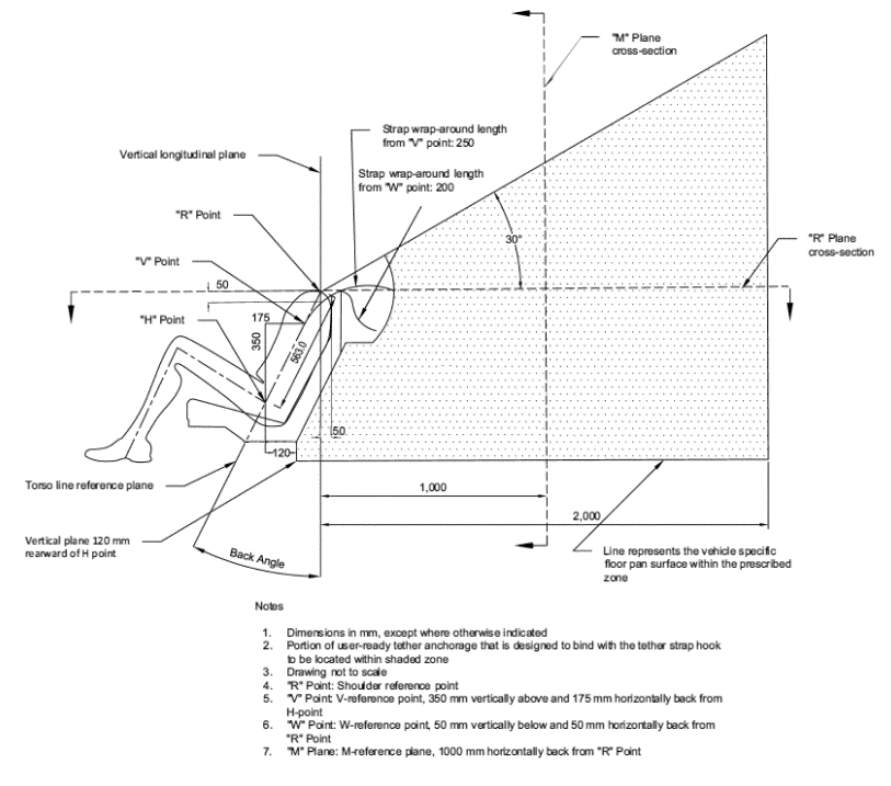
S6.2.2 Subject to S6.2.2.2, the part of each tether anchorage to which a tether hook attaches must be located within the shaded zone shown in figures 3 through 7 to this section of the designated seating position for which it is installed. The zone is defined with reference to the seating reference point (see §571.3). (For purposes of the figures, “H Point” means seating reference point.) A tether anchorage may be recessed in the seat back, provided that it is not in the strap wrap-around area at the top of the vehicle seat back. For the area under the vehicle seat, the forwardmost edge of the shaded zone is defined by a vertical plane 120 mm rearward of the “H Point,” as shown in figure 3 to this section.
S6.2.2.1 Subject to S6.2.2.2, for vehicles with adjustable or removable head restraints or no head restraints, the tether anchorage to which a tether hook attaches must be located outside the zone created by a 325 mm radius sphere with its center on the R-point and truncated horizontally at 230 mm below the sphere's center as shown in figures 8 and 9 to this section.
S6.2.2.2 In the case of a vehicle that—
(a) Has a user-ready tether anchorage for which no part of the shaded zone shown in figures 4 through 7 and 10 to this section of the designated seating position for which the anchorage is installed is accessible without the need for folding the seatback (other than the head restraint) or removing a seating component of the vehicle; and
(b) Has a tether strap routing device that is—
(1) Not less than 65 mm behind the torso line for that seating position, in the case of a flexible routing device or a deployable routing device, measured horizontally and in a vertical longitudinal plane; or
(2) Not less than 100 mm behind the torso line for that seating position, in the case of a fixed rigid routing device, measured horizontally and in a vertical longitudinal plane, the part of that anchorage that attaches to a tether hook may, at the manufacturer's option (with said option selected prior to, or at the time of, certification of the vehicle) be located outside that zone.
(c) The measurement of the location of the flexible or deployable routing device described in S6.2.2.2(b)(1) is made with SFAD 2 properly attached to the lower anchorages. A 40 mm wide nylon tether strap is routed through the routing device and attached to the tether anchorage in accordance with the written instructions required by S12 of this standard. The forwardmost contact point between the strap and the routing device must be within the stated limit when the tether strap is flat against the top surface of the SFAD and tensioned to 55 to 65 N. In seating positions without lower anchorages of a child restraint anchorage system, the SFAD 2 is held with its central lateral plane in the central vertical longitudinal plane of the seating position. The adjustable anchorage attaching bars of the SFAD 2 are replaced by spacers that end flush with the back surface of the SFAD 2.
S6.3 Strength requirements for tether anchorages. (a) When tested in accordance with S8, the tether anchorage must not separate completely from the vehicle seat or seat anchorage or the structure of the vehicle.
(b) Provisions for simultaneous and sequential testing:
(1) In the case of vehicle seat assemblies equipped with more than one tether anchorage, the force referred to in this S6.3 may, at the agency's option, be applied simultaneously to each of those tether anchorages. However, that force may not be applied simultaneously to tether anchorages for any two adjacent seating positions whose midpoints are less than 400 mm apart, as measured in accordance with S6.3(b)(i) and (ii) and figure 20 to this section.
(i) The midpoint of the seating position lies in the vertical longitudinal plane that is equidistant from vertical longitudinal planes through the geometric center of each of the two lower anchorages at the seating position. For those seating positions that do not provide lower anchorages, the midpoint of the seating position lies in the vertical longitudinal plane that passes through the SgRP of the seating position.
(ii) Measure the distance between the vertical longitudinal planes passing through the midpoints of the adjacent seating positions, as measured along a line perpendicular to the planes.
(2) A tether anchorage of a particular child restraint anchorage system will not be tested with the lower anchorages of that anchorage system if one or both of those lower anchorages have been previously tested under this standard.
S6.4 Marking and conspicuity requirements for tether anchorages. Vehicles subject to Standard No. 225 (this section) shall meet S6.4 according to the phase-in schedule specified in S13 of this standard.
(a) For each tether anchorage installed pursuant to S4 of this standard, there shall be a permanent marking that:
(1) Consists of one of the pictograms shown in figure 25 to this section that is not less than 20 mm in height;
(2) Except for vehicles that use a routing device per S6.2.2.2, the center of the pictogram in the longitudinal direction must be in the vertical longitudinal plane that passes through the center of the tether anchorage bar (± half of the tether anchorage length), as shown in figure 26 (Left) to this section; or the center of the pictogram in the lateral direction must be in the horizontal lateral plane that passes through the center of the tether anchorage bar (± half of the pictogram height), as shown in figure 26 (right) to this section.
(3) The nearest edge of the marking shall be located not more than 100 mm away from the tether anchorage bar as shown in figure 27 to this section. No other attachment feature to secure occupant items (i.e., cargo hooks or similar) shall be nearer to the marking than the distance from the marking to the tether anchorage. Vehicles with routing devices per S6.2.2.2 may use tags attached to the routing device.
(b) The tether anchorage bar may be covered by a cap or cover that is removable without the use of any tool, provided that the cap or cover is permanently labeled with a marking meeting the requirements of S6.4(a)(1). If the cap or cover is permanently attached to the vehicle, the tether anchorage is not required to be separately marked. If the cap or cover is not permanently attached to the vehicle, the tether anchorage must also be marked with the symbol meeting S6.4(a)(1) through (3).
(c) For vehicles that have a cargo cover that needs to be moved or removed to access the tether anchorages, the cargo cover must be permanently marked with the symbol meeting S6.4.1(a)(1) of this standard for each tether anchorage that is accessible under the cargo cover. Tether anchorages under the cargo cover must also be marked per S6.4(a).
* * * *
S8 Test procedures. Each vehicle shall meet the requirements of S6.3 when tested according to the following procedures. * * *
S8.1 Apply the force specified in S6.3 as follows—
* * * * *
S9. Requirements for the lower anchorages of the child restraint anchorage system. Vehicles subject to Standard No. 225 (this section) shall meet the lower anchorage requirements specified in S9.2 and S9.5 according to the phase-in schedule specified in S13 of this standard.
S9.1 Configuration of the lower anchorages
S9.1.1 * * *
(d) The bars must not be capable of being stowable or foldable.
* * * *
S9.2 Location of the lower anchorages.
* * * *
S9.5 Marking and conspicuity requirements.
S9.5.1 Requirements for lower anchors. Lower anchorages must meet the requirements in S9.5.1(a) or (b).
(a) For each bar installed pursuant to S4, the vehicle shall be permanently marked with a circle:
(1) That is not less than 13 mm in diameter;
(2) That is either solid or open, with or without words, symbols, or pictograms, provided that if words, symbols or pictograms are used, their meaning is explained to the consumer in writing, such as in the vehicle's owner's manual; and
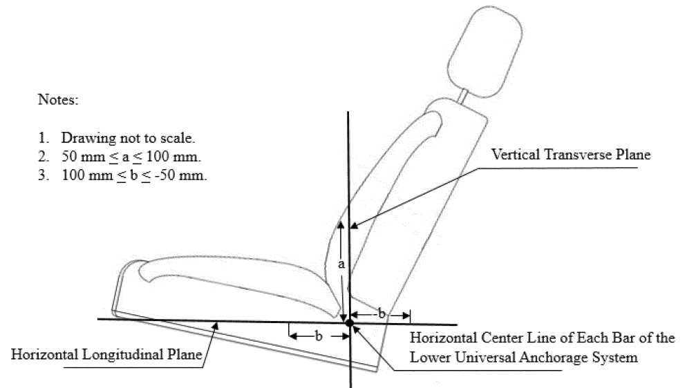
(3) That is located such that its center is on each seat back between 50 and 100 mm above or on the seat cushion 100 ±25 mm forward of the intersection of the vertical transverse and horizontal longitudinal planes intersecting at the horizontal centerline of each lower anchorage, as illustrated in figure 22 to this section. The center of the circle must be in the vertical longitudinal plane that passes through the center of the bar (±25 mm).
(4) The circle may be on a tag.
(b) The vehicle shall be configured such that the following is visible: Each of the bars installed pursuant to S4, or a permanently attached guide device for each bar. The bar or guide device must be visible without the compression of the seat cushion or seat back, when the bar or device is viewed, in a vertical longitudinal plane passing through the center of the bar or guide device, along a line making an upward 30-degree angle with a horizontal plane. Seat backs are in the nominal design riding position. The bars may be covered by a removable cap or cover, provided that the cap or cover is permanently marked with words, symbols or pictograms whose meaning is explained to the consumer in written form as part of the owner's manual.
S9.5.2 Requirements for lower anchors. Lower anchorages must meet the requirements in S9.5.2(a) and (b), as applicable.
(a) For each bar installed pursuant to S4, the vehicle shall be permanently marked with a symbol that:
(1) Is not less than 13 mm in diameter;
(2) Contains the pictogram shown in figure 24 to this section; and
(3) Is located such that its center is on each seat back between 50 and 100 mm above or on the seat cushion between 100 to −50 mm forward of the intersection of the vertical transverse and horizontal longitudinal planes intersecting at the horizontal centerline of each lower anchorage, as illustrated in figure 19 to this section. The center of the symbol must be in the vertical longitudinal plane that passes through the center of the bar (±25 mm).
(4) The symbol may be on a tag.
(b) The bars may be covered by a removable cap or cover, provided that the cap or cover is permanently marked with the pictogram shown in figure 24 to this section. If the cap or cover is permanently attached to the vehicle, the lower anchorage bars are not required to be separately marked with the pictogram. If the cap or cover is not permanently attached to the vehicle, the lower anchorage bars must also be marked with the symbol meeting S9.5.2(a)(1) through (4).
* * * *
S11. Test procedures. Each vehicle shall meet the requirements of this standard when tested according to the following procedures. Where a range of values is specified, the vehicle shall be able to meet the requirements at all points within the range.
(a) Strength requirements —(1) Forward force direction. Place SFAD 2 in the vehicle seating position and attach it to the two lower anchorages of the child restraint anchorage system. Do not attach the tether anchorage. A rearward horizontal force of 135 ±15 N is applied to the center of the lower front crossbar of SFAD 2 to press the device against the seat back as the fore-aft position of the rearward extensions of the SFAD is adjusted to remove any slack or tension. Apply a preload force of 500 N horizontally and in the vertical centerline of the SFAD 2 at point X. Increase the pull force as linearly as practicable to a full force application of 11,000 N in not less than 24 seconds and not more than 30 seconds and maintain at an 11,000 N level for 1 second.
(2) Lateral force direction. Place SFAD 2 in the vehicle seating position and attach it to the two lower anchorages of the child restraint anchorage system. Do not attach the tether anchorage. A rearward force of 135 ±15 N is applied to the center of the lower front crossbar of SFAD 2 to press the device against the seat back as the fore-aft position of the rearward extensions of the SFAD is adjusted to remove any slack or tension. Apply a preload force of 500 N horizontal and perpendicular to the longitudinal centerline of the SFAD 2 at point X of the test device. Increase the pull force as linearly as practicable to a full force application of 5,000 N in not less than 24 seconds and not more than 30 seconds and maintain at a 5,000 N level for 1 second.
(b) Clearance angle. The seat back angle, if adjustable, is set at the manufacturer's nominal design seat back angle. If the position is not specified, set the seat back at the first detent rearward of 25° from the vertical. Remove or open any lower anchorage cover, if present, to expose the lower anchorage. To measure clearance angle, attach the clearance angle tool to the lower anchorage and apply a vertical force of 67 N (15 lbf) to the tool. Measure the angle (with respect to the horizontal) of the tool while the force is being applied.
(c) Anchorage depth. The seat back angle, if adjustable, is set at the manufacturer's nominal design seat back angle. If the position is not specified, set the seat back at the first detent rearward of 25° from the vertical. To measure the anchorage depth, subtract 30 degrees from the measured seat pan angle to calculate the view angle. With the anchorage depth tool ( see figure 28 to this section) on a flat surface, adjust the view bar to read the view angle. Slide the zeroing strip along the view bar so that it is barely touching the top of the depth tool hook. Move the view bar forward, so the end of the zeroing strip is aligned with the zero-scribe line. For hidden anchorages, slide the anchorage depth tool so that it reads 0 mm at the rear edge of the slider. For visible anchorages, align the depth gauge to 25 mm so that negative values can be read. Attach the depth tool centered to the lower anchorage. Adjust the depth tool base to be within ±2 degrees of the view angle (30 degrees minus seat pan angle) to set the tool-parallel to the seat pan angle. Move the entire slider bar forward until the zeroing strip contacts the vehicle seat back or any other vehicle part.
S12. Written instructions. Vehicles subject to Standard No. 225 (this section) shall meet the written instruction requirements specified in either S12.1 or S12.2 according to the phase-in schedule specified in S13.
S12.1 Written instructions shall:
(a) Indicate which seating positions in the vehicle are equipped with tether anchorages and child restraint anchorage systems;
(b) In the case of vehicles required to be marked as specified in paragraphs S4.1 and S9.5 of this standard, explain the meaning of markings provided to locate the lower anchorages of child restraint anchorage systems; and
(c) Include instructions that provide a step-by-step procedure, including diagrams, for properly attaching a child restraint system's tether strap to the tether anchorages.
S12.2 Written instructions shall:
(a) Indicate which seating positions in the vehicle are equipped with tether anchorages and child restraint anchorage systems;
(b) In the case of vehicles required to be marked as specified in paragraphs S4.1 and S9.5 of this standard, explain the meaning of markings provided to locate the lower anchorages of child restraint anchorage systems and the top tether anchorages;
(c) Include instructions that provide a step-by-step procedure, including diagrams, for properly attaching a child restraint system's tether strap to the tether anchorages;
(d) Include instructions on how to locate and access the tether anchorage and the lower anchorages; and
(e) Use the following terms when referring to the different components of the child restraint anchorage system that are used to connect the child restraint system to the vehicle: “lower anchor” means the lower anchorage of the child restraint anchorage system in the vehicle, “tether anchor” means the top tether anchorage of the child restraint anchorage system in the vehicle, “lower anchor attachment” means the child restraint system or the detachable base's (in the case of a rear-facing child restraint with a detachable base) lower anchorage connector and the lower anchorage strap (for flexible lower anchorage attachments), “rigid lower anchor attachment” means the child restraint system or the detachable base's (in the case of a rear-facing child restraint with a detachable base) lower anchorage connector that is rigidly attached to the CRS or detachable base, respectively, and does not have a lower anchorage strap, and “tether” means the child restraints system's tether hook and tether strap.
S13 Phase-in schedule. The S13 phase in schedule details when listed requirements become inactive and are replaced by newer requirements. Requirements in Standard No. 225 (this section) not listed in S13 shall be in effect before, during, and after the S13 phase-in.
S13.1 Vehicle certification information. At any time during the production years ending August 31, 2029, and August 31, 2030, each manufacturer shall, upon request from the Office of Vehicle Safety Compliance, provide information identifying the vehicles (by make, model and vehicle identification number) that have been certified as complying with the child restraint anchorage usability requirements of this standard. Manufacturers shall specify the number of vehicles meeting each phase-in percentage. The manufacturer's designation of a vehicle as a certified vehicle is irrevocable.
S13.1.1 Pre phase-in. Vehicles manufactured before September 1, 2028, are subject to S6.1.1, S6.2.1, S9.2.1, S9.2.2, S9.2.3, S9.5.1, and S12.1 of this standard.
S13.1.2 Phase-in year 1. Vehicles manufactured on or after September 1, 2028, and before September 1, 2029. The total number of individual vehicles complying with S6.1.2, S6.2.2, S6.4, S9.2 (except for S9.2.2(a)), S9.5.2, and S12.2 of this standard shall be not less than 20 percent of a vehicle manufacturer's total production for this time period. The remaining 80 percent of a vehicle manufacturer's total production are subject to S6.1.1, S6.2.1, S9.2.1, S9.2.2, S9.2.3, S9.5.1, and S12.1 of this standard.
S13.1.3 Phase-in year 2. Vehicles manufactured on or after September 1, 2029, and before September 1, 2030. The total number of individual vehicles complying with S6.1.2, S6.2.2, S6.4, S9.2 (except for S9.2.2(a)), S9.5.2, and S12.2 of this standard shall be not less than 50 percent of a vehicle manufacturer's total production for this time period. The remaining 50 percent of a vehicle manufacturer's total production are subject to S6.1.1, S6.2.1, S9.2.1, S9.2.2, S9.2.3, S9.5.1, and S12.1 of this standard.
S13.1.4 Phase-in year 3 and beyond. Vehicles manufactured on or after September 1, 2030. The total number of vehicles complying with S6.1.2, S6.2.2, S6.4, S9.2 (except for S9.2.2(a)), S9.5.2, and S12.2 shall be not less than 100 percent of a vehicle manufacturer's total production.
S13.2 Vehicles produced by more than one manufacturer.
S13.2.1 For the purpose of calculating average annual production of vehicles for each manufacturer and the number of vehicles manufactured by each manufacturer under S13.1.1 through S13.1.4, a vehicle produced by more than one manufacturer shall be attributed to a single manufacturer as follows:
(a) A vehicle which is imported shall be attributed to the importer.
(b) A vehicle manufactured in the United States by more than one manufacturer, one of which also markets the vehicle, shall be attributed to the manufacturer which markets the vehicle.
S13.2.2 A vehicle produced by more than one manufacturer shall be attributed to any one of the vehicle's manufacturers specified by an express written contract, reported to the National Highway Traffic Safety Administration under 49 CFR part 585, between the manufacturers so specified and the manufacturer to which the vehicle would otherwise be attributed under S13.2.1.
Figures to §571.225
* * * * *
Figure 8 to §571.225. Side View of 325 mm Radius Sphere Zone From R-Point, Truncated at 230 mm Below the Center
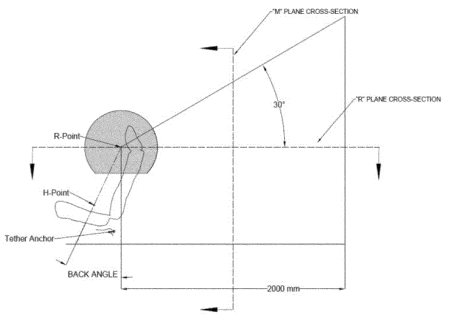
Figure 9 to §571.225. Three-Dimensional 325 mm Radius Sphere Zone From R-Point, Truncated Along the Lower Edge at 230 mm Below Its Center
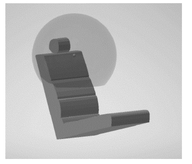
Figure 10 to §571.225—Side View. User Ready Tether Anchorage Location
* * * *
Figure 19 to §571.225. Placement of Symbol on the Seat Back and Seat Cushion of Vehicle


This final rule amends Federal Motor Vehicle Safety Standard (FMVSS) No. 225; Child restraint systems, and FMVSS No. 213b; Child restraint systems, to improve ease-of-use of the lower and tether anchorages, improve correct use of child restraint systems in vehicles, and maintain or improve the correct use and effectiveness of child restraint systems (CRSs) in motor vehicles. This final rule fulfills a mandate of the Moving Ahead for Progress in the 21st Century Act (MAP-21) requiring that NHTSA improve the ease-of-use for lower anchorages and tethers in all rear seat positions.
DATES:
Effective date: March 20, 2025.
IBR date: The incorporation by reference of certain publications listed in the rule is approved by the Director of the Federal Register beginning March 10, 2025.
Compliance date: This final rule adopts a 3-year phase-in period to comply with the updated requirements in FMVSS No. 225. The phase-in begins on September 1, 2028, and requires that 20 percent of a manufacturer's applicable vehicles produced from September 1, 2028, to August 31, 2029, comply with the updated FMVSS No. 225, followed by 50 percent from September 1, 2029, to August 31, 2030, and 100 percent on and after September 1, 2030. Early compliance is permitted.
Reconsideration date: If you wish to petition for reconsideration of this rule, your petition must be received by February 21, 2025.
Published in the Federal Register January 7, 2025, page 1288.
View final rule.
| §571.5 Matter incorporated by reference. | ||
| (k)(10)-(11) | Added | View text |
| §571.213b Child restraint systems; Mandatory applicability beginning December 5, 2026. | ||
| S5.5.2(j) | Revised | View text |
| S5.6.1.13 and S5.6.1.14 | Added | View text |
| S5.9(a) through (c) | Revised | View text |
| Figures 15 and 16 | Added | View text |
| §571.225 Child restraint anchorage systems. | ||
| S4.2 | Revised | View text |
| S4.3-S4.6 | Redesignated, revised | View text |
| S5 and S6 | Revised | View text |
| S8 introductory text and S8.1 introductory text | Revised | View text |
| S8.2 | Removed and reserved | View text |
| S9 introductory text, S9.1.1(d) and S9.2 | Revised | View text |
| S9.2.4 and S9.2.5 | Added | View text |
| S9.5 | Revised | View text |
| S11, S12, and S13 | Revised | View text |
| S14, S15, and S16 | Removed | View text |
| Figures 8, 9, 10, and 19 | Revised | View text |
| Figure 11 | Removed and reserved | View text |
| Figures 23 through 28 | Added | View text |
New Text
§571.213b Child restraint systems; Mandatory applicability beginning December 5, 2026.
* * * *
S5.5.2(j) In the case of each child restraint system equipped with a tether strap the statement: Secure the tether strap provided with this child restraint.
* * * *
S5.9 Attachment to child restraint anchorage system. (a) Each add-on child restraint system other than a car bed, harness, or belt-positioning seat shall have components permanently attached to the system that enable the restraint to be securely fastened to the lower anchorages of the child restraint anchorage system specified in Standard No. 225 (§571.225) and depicted in NHTSA Standard Seat Assembly; FMVSS No. 213, No. NHTSA-213-2021, (March 2023) (incorporated by reference, see §571.5). The components must be attached to the add-on child restraint by use of a tool, such as a screwdriver. In the case of rear-facing child restraints with detachable bases, only the base is required to have the components. All components provided to attach the add-on child restraint or the detachable base (in the case of a rear-facing child restraint with a detachable base) to the lower anchorages of the child restraint anchorage system shall be permanently marked with the pictogram in figure 15 to this section.
(b) In the case of each child restraint system that has components for attaching the system to a tether anchorage, those components shall include a tether hook that conforms to the configuration and geometry specified in figure 11 to this section. The tether hook or the tether strap shall be permanently marked with either pictogram shown in figure 16 to this section. If the mark is on the tether strap or on a tag attached to the tether strap, the mark must be located within 25 mm of the tether hardware assembly (which consists of a tether hook and a webbing tightening mechanism designed to tighten or loosen the tether strap).
(c) In the case of each child restraint system that has components, including belt webbing, for attaching the system to an anchorage of a child restraint anchorage system (lower anchorage or tether anchorage), the belt webbing shall be adjustable so that the child restraint can be tightly attached to the vehicle. The length of the tether hardware assembly, which consists of a tether hook and a mechanism designed to tighten and loosen the tether strap, shall not exceed 165 mm.
§571.225 Child restraint anchorage systems.
* * * *
S4.2 Vehicles shall be equipped as specified in paragraphs S4.2(a) through (c), except as provided in S5 of this standard.
(a) Each vehicle with three or more forward-facing rear designated seating positions shall be equipped as specified in S4.2(a)(1) and (2).
(1) Each vehicle shall be equipped with a child restraint anchorage system conforming to the requirements of S6 and S9 of this standard at not fewer than two forward-facing rear designated seating positions. At least one of the child restraint anchorage systems shall be installed at a forward-facing seating position in the second row in each vehicle that has three or more rows, if such a forward-facing seating position is available in that row.
(2) Each vehicle shall be equipped with a tether anchorage conforming to the requirements of S6 of this standard at a third forward-facing rear designated seating position. The tether anchorage of a child restraint anchorage system may count towards the third required tether anchorage. In each vehicle with a forward-facing rear designated seating position other than an outboard designated seating position, at least one tether anchorage (with or without the lower anchorages of a child restraint anchorage system) shall be at such a designated seating position.
(b) Each vehicle with not more than two forward-facing rear designated seating positions shall be equipped with a child restraint anchorage system conforming to the requirements of S6 and S9 of this standard at each forward-facing rear designated seating position.
(c) Each vehicle without any forward-facing rear designated seating position shall be equipped with a tether anchorage conforming to the requirements of S6 of this standard at each forward-facing front passenger designated seating position.
* * * *
S4.3 Movable seats. (a) A vehicle that is equipped with a forward-facing rear designated seating position that can be moved such that it is capable of being used at either an outboard or non-outboard forward-facing designated seating position shall be considered as having a forward-facing non-outboard designated seating position. Such a movable seat must be equipped with a tether anchorage that meets the requirements of S6 of this standard or a child restraint anchorage system that meets the requirements of S6 and S9 of this standard, if the vehicle does not have another forward-facing non-outboard designated seating position that is so equipped.
(b) Tether and lower anchorages shall be available for use at all times, except when the seating position for which it is installed is not available for use because the vehicle seat has been removed or converted to an alternate use such as allowing for the carrying of cargo.
* * * *
S5 General exceptions. Vehicles manufactured before September 1, 2031, must meet the requirements of S5.1. Vehicles manufactured on or after September 1, 2031, must meet the requirements of S5.2.
S5.1 Vehicles manufactured before September 1, 2031. (a) Convertibles and school buses are excluded from the requirements to be equipped with tether anchorages.
(b) A vehicle may be equipped with a built-in child restraint system conforming to the requirements of Standard No. 213 (§571.213) or Standard No. 213b (§571.213b) as applicable, instead of one of the required tether anchorages or child restraint anchorage systems.
(c) Vehicles with no air bag in front passenger designated position:
(1) Each vehicle that does not have a rear designated seating position and does not have an air bag installed at front passenger designated seating positions pursuant to a temporary exemption granted by NHTSA under 49 CFR part 555, must have a child restraint anchorage system installed at a front passenger designated seating position. In the case of convertibles, the front designated passenger seating position need have only the two lower anchorages meeting the requirements of S9 of this standard.
(2) Each vehicle that has a rear designated seating position and meets the conditions in S4.5.4.1(b) of Standard No. 208 (§571.208), and does not have an air bag installed at front passenger designated seating positions pursuant to a temporary exemption granted by NHTSA under 49 CFR part 555, must have a child restraint anchorage system installed at a front passenger designated seating position in place of one of the child restraint anchorage systems that is required for the rear seat. In the case of convertibles, the front designated passenger seating position need have only the two lower anchorages meeting the requirements of S9 of this standard.
(d) A vehicle that does not have an air bag on-off switch meeting the requirements of S4.5.4 of Standard No. 208 (§571.208) shall not have any child restraint anchorage system installed at a front designated seating position.
(e) A vehicle with a rear designated seating position for which interference with transmission and/or suspension components prevents the location of the lower bars of a child restraint anchorage system anywhere within the zone described by S9.2 of this standard is excluded from the requirement to provide a child restraint anchorage system at that position. However, except as provided elsewhere in this S5, such a vehicle must have a tether anchorage at a front passenger designated seating position.
S5.2 Vehicles manufactured on or after September 1, 2031. (a) School buses are excluded from the requirements to be equipped with tether anchorages.
(b) A vehicle may be equipped with a built-in child restraint system conforming to the requirements of Standard No. 213b (§571.213b) instead of one of the required tether anchorages or child restraint anchorage systems.
(c) Vehicles with no air bag in front passenger designated position:
(1) Each vehicle that does not have a rear designated seating position and does not have an air bag installed at front passenger designated seating positions pursuant to a temporary exemption granted by NHTSA under 49 CFR part 555 must have a child restraint anchorage system installed at a front passenger designated seating position.
(2) Each vehicle that has a rear designated seating position and meets the conditions in S4.5.4.1(b) of Standard No. 208 (§571.208), and does not have an air bag installed at front passenger designated seating positions pursuant to a temporary exemption granted by NHTSA under 49 CFR part 555, must have a child restraint anchorage system installed at a front passenger designated seating position in place of one of the child restraint anchorage systems that is required for the rear seat.
(d) A vehicle that does not have an air bag on-off switch meeting the requirements of S4.5.4 of Standard No. 208 (§571.208), shall not have any child restraint anchorage system installed at a front designated seating position.
S6. Requirements for tether anchorages. Vehicles subject to Standard No. 225 (this section) shall meet the tether anchorage requirements specified in S6.1, S6.2, and S6.4 according to the phase-in schedule specified in S13 of this standard.
S6.1 Configuration of the tether anchorage.
S6.1.1 Each tether anchorage shall:
(a) Permit the attachment of a tether hook of a child restraint system meeting the configuration and geometry specified in figure 11 of Standard No. 213 (figure 11 to §571.213);
(b) Be accessible without the need for any tools other than a screwdriver or coin;
(c) Once accessed, be ready for use without the need for any tools; and
(d) Be sealed to prevent the entry of exhaust fumes into the passenger compartment.
S6.1.2 Each tether anchorage shall:
(a) Consist of a rigid bar of any cross-section shape that permits the attachment of a tether hook (of a child restraint system) meeting the configuration and geometry specified in figure 11 of Standard No. 213 (figure 11 to §571.213), except in buses with a GVWR less than or equal to 10,000 pounds and vehicles that use a routing device per S6.2.1.2;
(b) Be accessible without the need for any tools and without folding the seat back (other than the head restraint) or removing carpet or other vehicle components (other than cargo covers) to access the anchorages. Individual tether anchorages may be covered with a cap, flap, or cover, provided that any cap, flap, or, cover is specifically designed to be opened, moved aside, or to otherwise give unobstructed access to the anchorage and is labeled with the symbol shown in figure 25 to this section;
(c) Once accessed, be ready for use without the need for any tools; and
(d) Be sealed to prevent the entry of exhaust fumes into the passenger compartment.
S6.2 Location of the tether anchorage.
S6.2.1 Subject to S6.2.1.2, the part of each tether anchorage that attaches to a tether hook must be located within the shaded zone shown in figures 3 through 7 to this section of the designated seating position for which it is installed. The zone is defined with reference to the seating reference point (see §571.3). (For purposes of the figures, “H Point” is defined to mean seating reference point.) A tether anchorage may be recessed in the seat back, provided that it is not in the strap wrap-around area at the top of the vehicle seat back. For the area under the vehicle seat, the forwardmost edge of the shaded zone is defined by the torso line reference plane.
S6.2.1.1 [Reserved]
S6.2.1.2 In the case of a vehicle that—
(a) Has a user-ready tether anchorage for which no part of the shaded zone shown in Figures 3 to 7 of this standard of the designated seating position for which the anchorage is installed is accessible without removing a seating component of the vehicle; and
(b) Has a tether strap routing device that is—
(1) Not less than 65 mm behind the torso line for that seating position, in the case of a flexible routing device or a deployable routing device, measured horizontally and in a vertical longitudinal plane; or
(2) Not less than 100 mm behind the torso line for that seating position, in the case of a fixed rigid routing device, measured horizontally and in a vertical longitudinal plane, the part of that anchorage that attaches to a tether hook may, at the manufacturer's option (with said option selected prior to, or at the time of, certification of the vehicle) be located outside that zone.
(c) The measurement of the location of the flexible or deployable routing device described in S6.2.1.2(b)(1) is made with SFAD 2 properly attached to the lower anchorages. A 40 mm wide nylon tether strap is routed through the routing device and attached to the tether anchorage in accordance with the written instructions required by S12 of this standard. The forwardmost contact point between the strap and the routing device must be within the stated limit when the tether strap is flat against the top surface of the SFAD and tensioned to 55 to 65 N. In seating positions without lower anchorages of a child restraint anchorage system, the SFAD 2 is held with its central lateral plane in the central vertical longitudinal plane of the seating position. The adjustable anchor attaching bars of the SFAD 2 are replaced by spacers that end flush with the back surface of the SFAD.
S6.2.2 Subject to S6.2.2.2, the part of each tether anchorage to which a tether hook attaches must be located within the shaded zone shown in figures 3 through 7 to this section of the designated seating position for which it is installed. The zone is defined with reference to the seating reference point (see §571.3). (For purposes of the figures, “H Point” means seating reference point.) A tether anchorage may be recessed in the seat back, provided that it is not in the strap wrap-around area at the top of the vehicle seat back. For the area under the vehicle seat, the forwardmost edge of the shaded zone is defined by a vertical plane 120 mm rearward of the “H Point,” as shown in figure 3 to this section.
S6.2.2.1 Subject to S6.2.2.2, for vehicles with adjustable or removable head restraints or no head restraints, the tether anchorage to which a tether hook attaches must be located outside the zone created by a 325 mm radius sphere with its center on the R-point and truncated horizontally at 230 mm below the sphere's center as shown in figures 8 and 9 to this section.
S6.2.2.2 In the case of a vehicle that—
(a) Has a user-ready tether anchorage for which no part of the shaded zone shown in figures 4 through 7 and 10 to this section of the designated seating position for which the anchorage is installed is accessible without the need for folding the seatback (other than the head restraint) or removing a seating component of the vehicle; and
(b) Has a tether strap routing device that is—
(1) Not less than 65 mm behind the torso line for that seating position, in the case of a flexible routing device or a deployable routing device, measured horizontally and in a vertical longitudinal plane; or
(2) Not less than 100 mm behind the torso line for that seating position, in the case of a fixed rigid routing device, measured horizontally and in a vertical longitudinal plane, the part of that anchorage that attaches to a tether hook may, at the manufacturer's option (with said option selected prior to, or at the time of, certification of the vehicle) be located outside that zone.
(c) The measurement of the location of the flexible or deployable routing device described in S6.2.2.2(b)(1) is made with SFAD 2 properly attached to the lower anchorages. A 40 mm wide nylon tether strap is routed through the routing device and attached to the tether anchorage in accordance with the written instructions required by S12 of this standard. The forwardmost contact point between the strap and the routing device must be within the stated limit when the tether strap is flat against the top surface of the SFAD and tensioned to 55 to 65 N. In seating positions without lower anchorages of a child restraint anchorage system, the SFAD 2 is held with its central lateral plane in the central vertical longitudinal plane of the seating position. The adjustable anchorage attaching bars of the SFAD 2 are replaced by spacers that end flush with the back surface of the SFAD 2.
S6.3 Strength requirements for tether anchorages. (a) When tested in accordance with S8, the tether anchorage must not separate completely from the vehicle seat or seat anchorage or the structure of the vehicle.
(b) Provisions for simultaneous and sequential testing:
(1) In the case of vehicle seat assemblies equipped with more than one tether anchorage, the force referred to in this S6.3 may, at the agency's option, be applied simultaneously to each of those tether anchorages. However, that force may not be applied simultaneously to tether anchorages for any two adjacent seating positions whose midpoints are less than 400 mm apart, as measured in accordance with S6.3(b)(i) and (ii) and figure 20 to this section.
(i) The midpoint of the seating position lies in the vertical longitudinal plane that is equidistant from vertical longitudinal planes through the geometric center of each of the two lower anchorages at the seating position. For those seating positions that do not provide lower anchorages, the midpoint of the seating position lies in the vertical longitudinal plane that passes through the SgRP of the seating position.
(ii) Measure the distance between the vertical longitudinal planes passing through the midpoints of the adjacent seating positions, as measured along a line perpendicular to the planes.
(2) A tether anchorage of a particular child restraint anchorage system will not be tested with the lower anchorages of that anchorage system if one or both of those lower anchorages have been previously tested under this standard.
S6.4 Marking and conspicuity requirements for tether anchorages. Vehicles subject to Standard No. 225 (this section) shall meet S6.4 according to the phase-in schedule specified in S13 of this standard.
(a) For each tether anchorage installed pursuant to S4 of this standard, there shall be a permanent marking that:
(1) Consists of one of the pictograms shown in figure 25 to this section that is not less than 20 mm in height;
(2) Except for vehicles that use a routing device per S6.2.2.2, the center of the pictogram in the longitudinal direction must be in the vertical longitudinal plane that passes through the center of the tether anchorage bar (± half of the tether anchorage length), as shown in figure 26 (Left) to this section; or the center of the pictogram in the lateral direction must be in the horizontal lateral plane that passes through the center of the tether anchorage bar (± half of the pictogram height), as shown in figure 26 (right) to this section.
(3) The nearest edge of the marking shall be located not more than 100 mm away from the tether anchorage bar as shown in figure 27 to this section. No other attachment feature to secure occupant items (i.e., cargo hooks or similar) shall be nearer to the marking than the distance from the marking to the tether anchorage. Vehicles with routing devices per S6.2.2.2 may use tags attached to the routing device.
(b) The tether anchorage bar may be covered by a cap or cover that is removable without the use of any tool, provided that the cap or cover is permanently labeled with a marking meeting the requirements of S6.4(a)(1). If the cap or cover is permanently attached to the vehicle, the tether anchorage is not required to be separately marked. If the cap or cover is not permanently attached to the vehicle, the tether anchorage must also be marked with the symbol meeting S6.4(a)(1) through (3).
(c) For vehicles that have a cargo cover that needs to be moved or removed to access the tether anchorages, the cargo cover must be permanently marked with the symbol meeting S6.4.1(a)(1) of this standard for each tether anchorage that is accessible under the cargo cover. Tether anchorages under the cargo cover must also be marked per S6.4(a).
* * * *
S8 Test procedures. Each vehicle shall meet the requirements of S6.3 when tested according to the following procedures. * * *
S8.1 Apply the force specified in S6.3 as follows—
* * * * *
S9. Requirements for the lower anchorages of the child restraint anchorage system. Vehicles subject to Standard No. 225 (this section) shall meet the lower anchorage requirements specified in S9.2 and S9.5 according to the phase-in schedule specified in S13 of this standard.
S9.1 Configuration of the lower anchorages
S9.1.1 * * *
(d) The bars must not be capable of being stowable or foldable.
* * * *
S9.2 Location of the lower anchorages.
* * * *
S9.5 Marking and conspicuity requirements.
S9.5.1 Requirements for lower anchors. Lower anchorages must meet the requirements in S9.5.1(a) or (b).
(a) For each bar installed pursuant to S4, the vehicle shall be permanently marked with a circle:
(1) That is not less than 13 mm in diameter;
(2) That is either solid or open, with or without words, symbols, or pictograms, provided that if words, symbols or pictograms are used, their meaning is explained to the consumer in writing, such as in the vehicle's owner's manual; and
(3) That is located such that its center is on each seat back between 50 and 100 mm above or on the seat cushion 100 ±25 mm forward of the intersection of the vertical transverse and horizontal longitudinal planes intersecting at the horizontal centerline of each lower anchorage, as illustrated in figure 22 to this section. The center of the circle must be in the vertical longitudinal plane that passes through the center of the bar (±25 mm).
(4) The circle may be on a tag.
(b) The vehicle shall be configured such that the following is visible: Each of the bars installed pursuant to S4, or a permanently attached guide device for each bar. The bar or guide device must be visible without the compression of the seat cushion or seat back, when the bar or device is viewed, in a vertical longitudinal plane passing through the center of the bar or guide device, along a line making an upward 30-degree angle with a horizontal plane. Seat backs are in the nominal design riding position. The bars may be covered by a removable cap or cover, provided that the cap or cover is permanently marked with words, symbols or pictograms whose meaning is explained to the consumer in written form as part of the owner's manual.
S9.5.2 Requirements for lower anchors. Lower anchorages must meet the requirements in S9.5.2(a) and (b), as applicable.
(a) For each bar installed pursuant to S4, the vehicle shall be permanently marked with a symbol that:
(1) Is not less than 13 mm in diameter;
(2) Contains the pictogram shown in figure 24 to this section; and
(3) Is located such that its center is on each seat back between 50 and 100 mm above or on the seat cushion between 100 to −50 mm forward of the intersection of the vertical transverse and horizontal longitudinal planes intersecting at the horizontal centerline of each lower anchorage, as illustrated in figure 19 to this section. The center of the symbol must be in the vertical longitudinal plane that passes through the center of the bar (±25 mm).
(4) The symbol may be on a tag.
(b) The bars may be covered by a removable cap or cover, provided that the cap or cover is permanently marked with the pictogram shown in figure 24 to this section. If the cap or cover is permanently attached to the vehicle, the lower anchorage bars are not required to be separately marked with the pictogram. If the cap or cover is not permanently attached to the vehicle, the lower anchorage bars must also be marked with the symbol meeting S9.5.2(a)(1) through (4).
* * * *
S11. Test procedures. Each vehicle shall meet the requirements of this standard when tested according to the following procedures. Where a range of values is specified, the vehicle shall be able to meet the requirements at all points within the range.
(a) Strength requirements —(1) Forward force direction. Place SFAD 2 in the vehicle seating position and attach it to the two lower anchorages of the child restraint anchorage system. Do not attach the tether anchorage. A rearward horizontal force of 135 ±15 N is applied to the center of the lower front crossbar of SFAD 2 to press the device against the seat back as the fore-aft position of the rearward extensions of the SFAD is adjusted to remove any slack or tension. Apply a preload force of 500 N horizontally and in the vertical centerline of the SFAD 2 at point X. Increase the pull force as linearly as practicable to a full force application of 11,000 N in not less than 24 seconds and not more than 30 seconds and maintain at an 11,000 N level for 1 second.
(2) Lateral force direction. Place SFAD 2 in the vehicle seating position and attach it to the two lower anchorages of the child restraint anchorage system. Do not attach the tether anchorage. A rearward force of 135 ±15 N is applied to the center of the lower front crossbar of SFAD 2 to press the device against the seat back as the fore-aft position of the rearward extensions of the SFAD is adjusted to remove any slack or tension. Apply a preload force of 500 N horizontal and perpendicular to the longitudinal centerline of the SFAD 2 at point X of the test device. Increase the pull force as linearly as practicable to a full force application of 5,000 N in not less than 24 seconds and not more than 30 seconds and maintain at a 5,000 N level for 1 second.
(b) Clearance angle. The seat back angle, if adjustable, is set at the manufacturer's nominal design seat back angle. If the position is not specified, set the seat back at the first detent rearward of 25° from the vertical. Remove or open any lower anchorage cover, if present, to expose the lower anchorage. To measure clearance angle, attach the clearance angle tool to the lower anchorage and apply a vertical force of 67 N (15 lbf) to the tool. Measure the angle (with respect to the horizontal) of the tool while the force is being applied.
(c) Anchorage depth. The seat back angle, if adjustable, is set at the manufacturer's nominal design seat back angle. If the position is not specified, set the seat back at the first detent rearward of 25° from the vertical. To measure the anchorage depth, subtract 30 degrees from the measured seat pan angle to calculate the view angle. With the anchorage depth tool ( see figure 28 to this section) on a flat surface, adjust the view bar to read the view angle. Slide the zeroing strip along the view bar so that it is barely touching the top of the depth tool hook. Move the view bar forward, so the end of the zeroing strip is aligned with the zero-scribe line. For hidden anchorages, slide the anchorage depth tool so that it reads 0 mm at the rear edge of the slider. For visible anchorages, align the depth gauge to 25 mm so that negative values can be read. Attach the depth tool centered to the lower anchorage. Adjust the depth tool base to be within ±2 degrees of the view angle (30 degrees minus seat pan angle) to set the tool-parallel to the seat pan angle. Move the entire slider bar forward until the zeroing strip contacts the vehicle seat back or any other vehicle part.
S12. Written instructions. Vehicles subject to Standard No. 225 (this section) shall meet the written instruction requirements specified in either S12.1 or S12.2 according to the phase-in schedule specified in S13.
S12.1 Written instructions shall:
(a) Indicate which seating positions in the vehicle are equipped with tether anchorages and child restraint anchorage systems;
(b) In the case of vehicles required to be marked as specified in paragraphs S4.1 and S9.5 of this standard, explain the meaning of markings provided to locate the lower anchorages of child restraint anchorage systems; and
(c) Include instructions that provide a step-by-step procedure, including diagrams, for properly attaching a child restraint system's tether strap to the tether anchorages.
S12.2 Written instructions shall:
(a) Indicate which seating positions in the vehicle are equipped with tether anchorages and child restraint anchorage systems;
(b) In the case of vehicles required to be marked as specified in paragraphs S4.1 and S9.5 of this standard, explain the meaning of markings provided to locate the lower anchorages of child restraint anchorage systems and the top tether anchorages;
(c) Include instructions that provide a step-by-step procedure, including diagrams, for properly attaching a child restraint system's tether strap to the tether anchorages;
(d) Include instructions on how to locate and access the tether anchorage and the lower anchorages; and
(e) Use the following terms when referring to the different components of the child restraint anchorage system that are used to connect the child restraint system to the vehicle: “lower anchor” means the lower anchorage of the child restraint anchorage system in the vehicle, “tether anchor” means the top tether anchorage of the child restraint anchorage system in the vehicle, “lower anchor attachment” means the child restraint system or the detachable base's (in the case of a rear-facing child restraint with a detachable base) lower anchorage connector and the lower anchorage strap (for flexible lower anchorage attachments), “rigid lower anchor attachment” means the child restraint system or the detachable base's (in the case of a rear-facing child restraint with a detachable base) lower anchorage connector that is rigidly attached to the CRS or detachable base, respectively, and does not have a lower anchorage strap, and “tether” means the child restraints system's tether hook and tether strap.
S13 Phase-in schedule. The S13 phase in schedule details when listed requirements become inactive and are replaced by newer requirements. Requirements in Standard No. 225 (this section) not listed in S13 shall be in effect before, during, and after the S13 phase-in.
S13.1 Vehicle certification information. At any time during the production years ending August 31, 2029, and August 31, 2030, each manufacturer shall, upon request from the Office of Vehicle Safety Compliance, provide information identifying the vehicles (by make, model and vehicle identification number) that have been certified as complying with the child restraint anchorage usability requirements of this standard. Manufacturers shall specify the number of vehicles meeting each phase-in percentage. The manufacturer's designation of a vehicle as a certified vehicle is irrevocable.
S13.1.1 Pre phase-in. Vehicles manufactured before September 1, 2028, are subject to S6.1.1, S6.2.1, S9.2.1, S9.2.2, S9.2.3, S9.5.1, and S12.1 of this standard.
S13.1.2 Phase-in year 1. Vehicles manufactured on or after September 1, 2028, and before September 1, 2029. The total number of individual vehicles complying with S6.1.2, S6.2.2, S6.4, S9.2 (except for S9.2.2(a)), S9.5.2, and S12.2 of this standard shall be not less than 20 percent of a vehicle manufacturer's total production for this time period. The remaining 80 percent of a vehicle manufacturer's total production are subject to S6.1.1, S6.2.1, S9.2.1, S9.2.2, S9.2.3, S9.5.1, and S12.1 of this standard.
S13.1.3 Phase-in year 2. Vehicles manufactured on or after September 1, 2029, and before September 1, 2030. The total number of individual vehicles complying with S6.1.2, S6.2.2, S6.4, S9.2 (except for S9.2.2(a)), S9.5.2, and S12.2 of this standard shall be not less than 50 percent of a vehicle manufacturer's total production for this time period. The remaining 50 percent of a vehicle manufacturer's total production are subject to S6.1.1, S6.2.1, S9.2.1, S9.2.2, S9.2.3, S9.5.1, and S12.1 of this standard.
S13.1.4 Phase-in year 3 and beyond. Vehicles manufactured on or after September 1, 2030. The total number of vehicles complying with S6.1.2, S6.2.2, S6.4, S9.2 (except for S9.2.2(a)), S9.5.2, and S12.2 shall be not less than 100 percent of a vehicle manufacturer's total production.
S13.2 Vehicles produced by more than one manufacturer.
S13.2.1 For the purpose of calculating average annual production of vehicles for each manufacturer and the number of vehicles manufactured by each manufacturer under S13.1.1 through S13.1.4, a vehicle produced by more than one manufacturer shall be attributed to a single manufacturer as follows:
(a) A vehicle which is imported shall be attributed to the importer.
(b) A vehicle manufactured in the United States by more than one manufacturer, one of which also markets the vehicle, shall be attributed to the manufacturer which markets the vehicle.
S13.2.2 A vehicle produced by more than one manufacturer shall be attributed to any one of the vehicle's manufacturers specified by an express written contract, reported to the National Highway Traffic Safety Administration under 49 CFR part 585, between the manufacturers so specified and the manufacturer to which the vehicle would otherwise be attributed under S13.2.1.
Figures to §571.225
* * * * *
Figure 8 to §571.225. Side View of 325 mm Radius Sphere Zone From R-Point, Truncated at 230 mm Below the Center
Figure 9 to §571.225. Three-Dimensional 325 mm Radius Sphere Zone From R-Point, Truncated Along the Lower Edge at 230 mm Below Its Center
Figure 10 to §571.225—Side View. User Ready Tether Anchorage Location
* * * *
Figure 19 to §571.225. Placement of Symbol on the Seat Back and Seat Cushion of Vehicle


Specialized Industries

Interact With Our Compliance Experts

Upcoming Events


Most Recent Highlights In Environmental


Most Recent Highlights In Transportation


Most Recent Highlights In Safety & Health
Most Recent Highlights In Human Resources

Most Popular Highlights In Environmental


Most Popular Highlights In Transportation
Most Popular Highlights In Human Resources


Most Popular Highlights In Safety & Health


Saved to my EVENT CALENDAR!
View your saved links by clicking the arrow next to your profile picture located in the header. Then, click “My Activity” to view the Event Calendar on your Activity page.
OK