Compliance Just Got Easier: Stay ahead of regulatory changes with instant notifications on updates that matter.
['Business planning - Motor Carrier']
['Business planning - Motor Carrier']
2023-12-05T06:00:00Z
JOIN TODAY TO CONTINUE READING THIS ARTICLE & OTHER INDUSTRY NEWS!
You'll also get exclusive access to:
A database of easy-to-understand regulationsAsk unlimited questions to our expertsPre-led discussions forumsAnd more
TRY IT FREE TODAY
Already have an account? Log in now.

Copyright 2026 J. J. Keller & Associate, Inc. For re-use options please contact copyright@jjkeller.com or call 800-558-5011.
This final rule amends a Federal Motor Vehicle Safety Standard (FMVSS) regarding child restraint systems. The amendments, mandatory in one year, modernize the standard by, among other things, updating CRS owner registration program requirements, labeling requirements on correctly using child restraints, requirements for add-on school bus-specific child restraint systems, and provisions for NHTSA's use of test dummies in NHTSA compliance tests. Amendments mandatory in three years include adding a new FMVSS that updates to standard seat assemblies on which NHTSA tests child restraint systems for compliance with frontal crash performance requirements. This final rule fulfills a mandate of the Moving Ahead for Progress in the 21st Century Act (MAP–21) that directs NHTSA to update the standard seat assembly. The purpose of this final rule is to ensure continued effectiveness of child restraint systems in current and future vehicles.
DATES:
Effective date: February 5, 2024.
IBR date: The incorporation by reference of certain publications listed in the rule is approved by the Director of the Federal Register as of February 5, 2024. The incorporation by reference of certain other publications listed in the rule was approved by the Director as of February 6, 2012.
Compliance date: The compliance date for the amendments to FMVSS No. 213 is December 5, 2024. The compliance date for meeting FMVSS No. 213b is December 5, 2026. Optional early compliance with the standards is permitted.
Reconsideration date: If you wish to petition for reconsideration of this rule, your petition must be received by January 19, 2024.
Published in theFederal Register December 5, 2023, page 84514.
| §571.5 Matter incorporated by reference. | ||
| (b)(3) | Added | View text |
| (d)(16) | Revised | View text |
| (d)(22)-(d)(39) | Redesignated | View text |
| (k)(6)-(7) | Added | View text |
| (l)(3)-(4) | Revised | View text |
| §571.213 Child restraint systems; Applicable unless a vehicle or child restraint system is certified to §571.213b. | ||
| Entire section | Revised | View text |
| §571.213b Standard No. 213b; Child restraint systems; Mandatory applicability beginning | ||
| Entire section | Added | View text |
New Text
§571.5 Matter incorporated by reference.
* * * *
(d)(16) ASTM D1056-07, Standard Specification for Flexible Cellular Materials-Sponge or Expanded Rubber, approved March 1, 2007; into§§571.213;571.213b.
* * * *
(l)(3) SAE Recommended Practice J211, Instrumentation for Impact Tests, revised June 1980; into §571.218.
(l)(4) SAE Recommended Practice J211/1, Instrumentation for Impact Tests—Part 1— Electronic Instrumentation; revised March 1995;§§571.202a;571.208;571.213;571.213a;571.213b;571.218;571.403.
§571.213 Child restraint systems; Applicable unless a vehicle or child restraint system is certified to § 571.213b.
S1.Scope. This standard specifies requirements for child restraint systems used in motor vehicles and aircraft.
S2.Purpose. The purpose of this standard is to reduce the number of children killed or injured in motor vehicle crashes and in aircraft.
S3.Application. This standard applies to passenger cars, multipurpose passenger vehicles, trucks and buses, and to child restraint systems for use in motor vehicles and aircraft, manufactured before December 5, 2026. FMVSS No. 213b applies to child restraint systems manufactured on or after December 5, 2026.
S4.Definitions.
Add-on child restraint system
means any portable child restraint system.
Backless child restraint system
means a child restraint, other than a belt-positioning seat, that consists of a seating platform that does not extend up to provide a cushion for the child’s back or head and has a structural element designed to restrain forward motion of the child’s torso in a forward impact.
Belt-positioning seat
means a child restraint system that positions a child on a vehicle seat to improve the fit of a vehicle Type II belt system on the child and that lacks any component, such as a belt system or a structural element, designed to restrain forward movement of the child’s torso in a forward impact.
Booster seat
means either a backless child restraint system or a belt-positioning seat.
Built-in child restraint system
means a child restraint system that is designed to be an integral part of and permanently installed in a motor vehicle.
Car bed
means a child restraint system designed to restrain or position a child in the supine or prone position on a continuous flat surface.
Child restraint anchorage system
is defined in S3 of FMVSS No. 225 (§571.225).
Child restraint system
means any device, except Type I or Type II seat belts, designed for use in a motor vehicle or aircraft to restrain, seat, or position children who weigh 36 kilograms (kg) (80 lb) or less.
Contactable surface
means any child restraint system surface (other than that of a belt, belt buckle, or belt adjustment hardware) that may contact any part of the head or torso of the appropriate test dummy, specified in S7, when a child restraint system is tested in accordance with S6.1.
Factory-installed built-in child restraint system
means a built-in child restraint system that has been or will be permanently installed in a motor vehicle before that vehicle is certified as a completed or altered vehicle in accordance with part 567 of this chapter.
Harness
means a combination pelvic and upper torso child restraint system that consists primarily of flexible material, such as straps, webbing or similar material, and that does not include a rigid seating structure for the child.
Rear-facing child restraint system
means a child restraint system, except a car bed, that positions a child to face in the direction opposite to the normal direction of travel of the motor vehicle.
Representative aircraft passenger seat
means either a Federal Aviation Administration approved production aircraft passenger seat or a simulated aircraft passenger seat conforming to Figure 6.
School bus child restraint system means an add-on child restraint system (including a harness) manufactured and sold only for use on school bus seats, that has a label conforming with S5.3.1(b). (This definition applies to child restraint systems manufactured on or after December 5, 2024.)
Seat orientation reference line or SORL
means the horizontal line through Point Z as illustrated in Figure 1A.
Specific vehicle shell
means the actual vehicle model part into which the built-in child restraint system is or is intended to be fabricated, including the complete surroundings of the built-in system. If the built-in child restraint system is or is intended to be fabricated as part of any seat other than a front seat, these surroundings include the back of the seat in front, the interior rear side door panels and trim, the floor pan, adjacent pillars (e.g., the B and C pillars), and the ceiling. If the built-in system is or is intended to be fabricated as part of the front seat, these surroundings include the dashboard, the steering mechanism and its associated trim hardware, any levers and knobs installed on the floor or on a console, the interior front side door panels and trim, the front seat, the floor pan, the A pillars and the ceiling.
Tether anchorage
is defined in S3 of FMVSS No. 225 (§571.225).
Tether strap
is defined in S3 of FMVSS No. 225 (§571.225).
Tether hook
is defined in S3 of FMVSS No. 225 (§571.225).
Torso
means the portion of the body of a seated anthropomorphic test dummy, excluding the thighs, that lies between the top of the child restraint system seating surface and the top of the shoulders of the test dummy.
S5.Requirements.(a) Each motor vehicle with a built-in child restraint system shall meet the requirements in this section when, as specified, tested in accordance with S6.1 and this paragraph.
(b) Each child restraint system manufactured for use in motor vehicles shall meet the requirements in this section when, as specified, tested in accordance with S6.1 and this paragraph. Each add-on system shall meet the requirements at each of the restraint’s seat back angle adjustment positions and restraint belt routing positions, when the restraint is oriented in the direction recommended by the manufacturer (e.g., forward, rearward or laterally) pursuant to S5.6, and tested with the test dummy specified in S7.
(c) Each child restraint system manufactured for use in aircraft shall meet the requirements in this section and the additional requirements in S8.
(d) Each child restraint tested with a Part 572 Subpart S dummy need not meet S5.1.2 and S5.1.3.
(e) Each child restraint system tested with a part 572 subpart T dummy need not meet S5.1.2.1(a).
(f) Each child restraint system that is equipped with an internal harness or other internal components to restrain the child need not meet this standard when attached to the lower anchors of the child restraint anchorage system on the standard seat assembly if the sum of the weight of the child restraint system (in pounds) and the average weight of child represented by the test dummy used to test the child restraint in accordance with S7 of this standard, shown in the table below, exceeds 65 pounds. Such a child restraint must meet this standard when tested using its internal harness or components to restrain such a test dummy while installed using the standard seat belt assembly specified in S5.3.2 of this standard.
| Test dummy (specified in S7 of this standard) | Average weight of child represented by test dummy (pounds) |
| CRABI 12-month-old infant dummy (49 CFR Part 572, Subpart R) | 22 |
| Hybrid III 3-year-old dummy(49 CFR Part 572, Subpart P) | 31 |
| Hybrid III 6-year-old dummy 49 CFR Part 572, Subpart N) | 45 |
| Hybrid III 6-year-old weighted child test dummy (49 CFR Part 572 Subpart S) | 62 |
| Hybrid II 6-year-old dummy (49, CFR Part 572, Subpart I) | 45 |
(g) Each add-on child restraint system manufactured for use in motor vehicles, that is recommended for children in a weight range that includes weights up to 18 kilograms (40 pounds), or for children in a height range that includes heights up to 1100 millimeters, shall meet the requirements in this standard and the additional side impact protection requirements in Standard No. 213a (§571.213a). Excepted from Standard No. 213a are harnesses and car beds.
S5.1Dynamic performance.
S5.1.1Child restraint system integrity. When tested in accordance with S6.1, each child restraint system shall meet the requirements of paragraphs (a) through (c) of this section.
(a) Exhibit no complete separation of any load bearing structural element and no partial separation exposing either surfaces with a radius of less than 1⁄ 4 inch or surfaces with protrusions greater than 3⁄ 8 inch above the immediate adjacent surrounding contactable surface of any structural element of the system.
(b)(1) If adjustable to different positions, remain in the same adjustment position during the testing that it was in immediately before the testing, except as otherwise specified in paragraph (b)(2).
(2)(i) Subject to paragraph (b)(2)(ii), a rear-facing child restraint system may have a means for repositioning the seating surface of the system that allows the system’s occupant to move from a reclined position to an upright position and back to a reclined position during testing.
(ii) No opening that is exposed and is larger than 1⁄ 4 inch before the testing shall become smaller during the testing as a result of the movement of the seating surface relative to the restraint system as a whole.
(c) If a front facing child restraint system, not allow the angle between the system’s back support surfaces for the child and the system’s seating surface to be less than 45 degrees at the completion of the test.
S5.1.2Injury criteria. When tested in accordance with S6.1 and with the test dummies specified in S7, each child restraint system manufactured before August 1, 2005, that, in accordance with S5.5.2, is recommended for use by children whose mass is more than 10 kg shall—
(a) Limit the resultant acceleration at the location of the accelerometer mounted in the test dummy head as specified in part 572 such that the expression:
shall not exceed 1,000, where a is the resultant acceleration expressed as a multiple of g (the acceleration of gravity), and t 1 and t 2 are any two moments during the impacts.
(b) Limit the resultant acceleration at the location of the accelerometer mounted in the test dummy upper thorax as specified in part 572 to not more than 60 g’s, except for intervals whose cumulative duration is not more than 3 milliseconds.
S5.1.2.1 When tested in accordance with S6.1 and with the test dummies specified in S7, each child restraint system manufactured on or after August 1, 2005 shall’
(a) Limit the resultant acceleration at the location of the accelerometer mounted in the test dummy head such that, for any two points in time, t1 and t2, during the event which are separated by not more than a 36 millisecond time interval and where t1 is less than t2, the maximum calculated head injury criterion (HIC36 ) shall not exceed 1,000, determined using the resultant head acceleration at the center of gravity of the dummy head, ar, expressed as a multiple of g (the acceleration of gravity), calculated using the expression:
(b) The resultant acceleration calculated from the output of the thoracic instrumentation shall not exceed 60 g’s, except for intervals whose cumulative duration is not more than 3 milliseconds.
S5.1.2.2 At the manufacturer’s option (with said option irrevocably selected prior to, or at the time of, certification of the restraint), child restraint systems manufactured before August 1, 2005 may be tested to the requirements of S5 while using the test dummies specified in S7.1.2 of this standard according to the criteria for selecting test dummies specified in that paragraph. That paragraph specifies the dummies used to test child restraint systems manufactured on or after August 1, 2005. If a manufacturer selects the dummies specified in S7.1.2 to test its product, the injury criteria specified by S5.1.2.1 of this standard must be met. Child restraints manufactured on or after August 1, 2005 must be tested using the test dummies specified in S7.1.2.
S5.1.3Occupant excursion. When tested in accordance with S6.1 and the requirements specified in this section, each child restraint system shall meet the applicable excursion limit requirements specified in S5.1.3.1-S5.1.3.3.
S5.1.3.1Child restraint systems other than rear-facing ones and car beds. Each child restraint system, other than a rear-facing child restraint system or a car bed, shall retain the test dummy’s torso within the system.
(a) For each add-on child restraint system:
(1) No portion of the test dummy’s head shall pass through a vertical transverse plane that is 720 mm or 813 mm (as specified in the table in this S5.1.3.1) forward of point Z on the standard seat assembly, measured along the center SORL (as illustrated in figure 1B of this standard); and
(2) Neither knee pivot point shall pass through a vertical transverse plane that is 915 mm forward of point Z on the standard seat assembly, measured along the center SORL.
| When this type of child restraint | Is tested in accordance with— | These excursion limits apply | Explanatory note: in the test specified in 2nd column, the child restraint is attached to the test seat assembly in the manner described below, subject to certain conditions |
|---|---|---|---|
| Harnesses and restraints designed for use by children with physical disabilities | S6.1.2(a)(1)(i)(A) | Head 813 mm; Knee 915 mm | Attached with lap belt; in addition, if a tether is provided, it is attached. |
| Harnesses labeled per S5.3.1(b)(i) through S5.3.1(b)(iii) and Figure 12 | S6.1.2(a)(1)(i)(A) | Head 813 mm; Knee 915 mm | Attached with seat back mount. |
| Belt-positioning seats | S6.1.2(a)(1)(ii) | Head 813 mm; Knee 915 mm | Attached with lap and shoulder belt; no tether is attached. |
| All other child restraints (i.e., other than harnesses, restraints designed for use by children with physical disabilities, harnesses manufactured exclusively for school buses, and belt-positioning seats) | S6.1.2(a)(1)(i)(B) | Head 813 mm; Knee 915 mm | Attached with a lap belt, without a tether attached; and, Attached to lower anchorages of a child restraint anchorage system; no tether is attached. |
| All other child restraints (i.e., other than harnesses, restraints designed for use by children with physical disabilities, harnesses labeled per S5.3.1(b)(i) through S5.3.1(b)(iii) and Figure 12, and belt-positioning seats) | S6.1.2(a)(1)(i)(A), S6.1.2(a)(1)(i)(C) | Head 720 mm; Knee 915 mm | Attached with a lap belt, with a tether attached; and, Attached to lower anchorages of child restraint anchorage system, with a tether attached. |
| When this type of child restraint | Is tested in accordance with— | These excursion limits apply | Explanatory note: in the test specified in 2nd column, the excursion requirement must be met when the child restraint system is attached to the test seat assembly in the manner described below, subject to certain conditions |
|---|---|---|---|
| Harnesses and restraints designed for use by children with physical disabilities | S6.1.2(a)(1)(i)(A) | Head 813 mm; Knee 915 mm | Attached with lap and shoulder belt; in addition, if a tether is provided, it is attached. |
| School bus child restraint systems | S6.1.2(a)(1)(i)(A) | Head 813 mm; Knee 915 mm | Attached with seat back mount, or, seat back, and, seat pan mounts. |
| Booster seats | S6.1.2(a)(1)(ii) | Head 813 mm; Knee 915 mm | Attached with lap and shoulder belt; no tether is attached. |
| Child restraints other than harnesses, restraints designed for use by children with physical disabilities, school bus child restraint systems, and booster seats | S6.1.2(a)(1)(i)(B) | Head 813 mm; Knee 915 mm | Attached with a lap belt; without a tether attached. Attached to lower anchorages of child restraint anchorage system; with no tether attached. |
| Child restraints other than harnesses, restraints designed for use by children with physical disabilities, and school bus child restraint systems | S6.1.2(a)(1)(i)(A), S6.1.2(a)(1)(i)(C) | Head 720 mm; Knee 915 mm | Attached with a lap belt, with a tether attached. Attached to lower anchorages of child restraint anchorage system, with a tether attached. |
| Child restraints equipped with a fixed or movable surface described in S5.2.2.2 that has belts that are not an integral part of that fixed or movable surface | S6.1.2(a)(2) | Head 813 mm; Knee 915 mm | Attached with lap belt, no tether is attached. |
(b) In the case of a built-in child restraint system, neither knee pivot point shall, at any time during the dynamic test, pass through a vertical transverse plane that is 305 mm forward of the initial pre-test position of the respective knee pivot point, measured along a horizontal line that passes through the knee pivot point and is parallel to the vertical longitudinal plane that passes through the vehicle’s longitudinal centerline.
S5.1.3.2Rear-facing child restraint systems. In the case of each rear-facing child restraint system, all portions of the test dummy’s torso shall be retained within the system and neither of the target points on either side of the dummy’s head and on the transverse axis passing through the center of mass of the dummy’s head and perpendicular to the head’s midsagittal plane, shall pass through the transverse orthogonal planes whose intersection contains the forward-most and top-most points on the child restraint system surfaces (illustrated in Figure 1C).
S5.1.3.3Car beds. In the case of car beds, all portions of the test dummy’s head and torso shall be retained within the confines of the car bed.
S5.1.4Back support angle. When a rear-facing child restraint system is tested in accordance with S6.1, the angle between the system’s back support surface for the child and the vertical shall not exceed 70 degrees.
S5.2Force distribution.
S5.2.1Minimum head support surface—child restraints other than car beds.
S5.2.1.1 Except as provided in S5.2.1.2, each child restraint system other than a car bed shall provide restraint against rearward movement of the head of the child (rearward in relation to the child) by means of a continuous seat back which is an integral part of the system and which—
(a) Has a height, measured along the system seat back surface for the child in the vertical longitudinal plane passing through the longitudinal centerline of the child restraint systems from the lowest point on the system seating surface that is contacted by the buttocks of the seated dummy, as follows:
| Weight1 | Height2 (mm) |
|---|---|
| Not more than 18 kg........................................ | 500 |
| More than 18 kg............................................... | 560 |
1 When a child restraint system is recommended under S5.5 for use by children of the above weights.
2 The height of the portion of the system seat back providing head restraint shall not be less than the above.
(b) Has a width of not less than 8 inches, measured in the horizontal plane at the height specified in paragraph (a) of this section. Except that a child restraint system with side supports extending at least 4 inches forward from the padded surface of the portion of the restraint system provided for support of the child’s head may have a width of not less than 6 inches, measured in the horizontal plane at the height specified in paragraph (a) of this section.
(c) Limits the rearward rotation of the test dummy head so that the angle between the head and torso of the dummy specified in S7. when tested in accordance with S6.1 is not more than 45 degrees greater than the angle between the head and torso after the dummy has been placed in the system in accordance with S6.1.2.3 and before the system is tested in accordance with S6.1.
S5.2.1.2 The applicability of the requirements of S5.2.1.1 to a front-facing child restraint, and the conformance of any child restraint other than a car bed to those requirements, is determined using the largest of the test dummies specified in S7 for use in testing that restraint, provided that the 6-year-old dummy described in subpart I or subpart N of part 572 of this title and the 10-year-old dummy described in subpart T of part 572 of this title, are not used to determine the applicability of or compliance with S5.2.1.1. A front facing child restraint system is not required to comply with S5.2.1.1 if the target point on either side of the dummy's head is below a horizontal plane tangent to the top of—
(a) The standard seat assembly, in the case of an add-on child restraint system, when the dummy is positioned in the system and the system is installed on the assembly in accordance with S6.1.2.
(b) The vehicle seat, in the case of a built-in child restraint system, when the system is activated and the dummy is positioned in the system in accordance with S6.1.2.
S5.2.2Torso impact protection. Each child restraint system other than a car bed shall comply with the applicable requirements of S5.2.2.1 and S5.2.2.2.
S5.2.2.1(a) The system surface provided for the support of the child’s back shall be flat or concave and have a continuous surface area of not less than 85 square inches.
(b) Each system surface provided for support of the side of the child’s torso shall be flat or concave and have a continuous surface of not less than 24 square inches for systems recommended for children weighing 20 pounds or more, or 48 square inches for systems recommended for children weighing less than 20 pounds.
(c) Each horizontal cross section of each system surface designed to restrain forward movement of the child’s torso shall be flat or concave and each vertical longitudinal cross section shall be flat or convex with a radius of curvature of the underlying structure of not less than 2 inches.
S5.2.2.2 Each forward-facing child restraint system shall have no fixed or movable surface—
(a) Directly forward of the dummy and intersected by a horizontal line—
(1) Parallel to the SORL, in the case of the add-on child restraint system, or
(2) Parallel to a vertical plane through the longitudinal center line of the vehicle seat, in the case of a built-in child restraint system, and,
(b) Passing through any portion of the dummy, except for surfaces which restrain the dummy when the system is tested in accordance with S6.1.2(a)(2), so that the child restraint system shall conform to the requirements of S5.1.2 and S5.1.3.1.
S5.2.3 [Reserved]
S5.2.4Protrusion limitation. Any portion of a rigid structural component within or underlying a contactable surface, or any portion of a child restraint system surface that is subject to the requirements of S5.2.3 shall, with any padding or other flexible overlay material removed, have a height above any immediately adjacent restraint system surface of not more than3/8 inch and no exposed edge with a radius of less than1/4 inch.
S5.3Installation.
S5.3.1 Add-on child restraints shall meet either (a) or (b), as appropriate.
(a) Except for components designed to attach to a child restraint anchorage system, each add-on child restraint system must not have any means designed for attaching the system to a vehicle seat cushion or vehicle seat back and any component (except belts) that is designed to be inserted between the vehicle seat cushion and vehicle seat back.
(b) School bus child restraint systems (including harnesses manufactured for use on school bus seats) must have a label that conforms in content to Figure 12 and to the requirements of S5.3.1(b)(1) through S5.3.1(b)(3) of this standard. The label must be permanently affixed to the part of the school bus child restraint system, that attaches the system to a vehicle seat back.
(1) The label must be plainly visible when installed and easily readable.
(2) The message area must be white with black text. The message area must be no less than 20 square centimeters.
(3) The pictogram shall be gray and black with a red circle and slash on a white background. The pictogram shall be no less than 20 mm in diameter.
(c) The provision that add-on child restraint systems shall meet the requirements of this standard when installed solely by a Type 1 belt applies to child restraint systems manufactured before September 1, 2029. Except for harnesses, the requirement sunsets for child restraint systems manufactured on or after September 1, 2029. For harnesses, the requirement does not sunset and continues to apply to harnesses manufactured on or after September 1, 2029.
S5.3.2 Each add-on child restraint system shall be capable of meeting the requirements of this standard when installed solely by each of the means indicated in the following table for the particular type of child restraint system:
| Type of add-on child restraint system | Means of installation | ||||
|---|---|---|---|---|---|
| Type 1 seat belt assembly | Type 1 seat belt assembly plus a tether anchorage, if needed | Child restraint anchorage system (effective September 1, 2002) | Type II seat belt assembly | Seat back mount | |
| Harnesses labeled per S5.3.1(b)(1) through S5.3.1(b)(3) and Figure 12 | X | ||||
| Other harnesses | X | ||||
| Car beds | X | ||||
| Rear-facing restraints | X | X | |||
| Belt-positioning seats | X | ||||
| All other child restraints | X | X | X | ||
S5.3.2.1 School bus child restraint systems manufactured on or after December 5, 2024, shall be capable of meeting the requirements of this standard when installed by seat back mount, or, seat back mount and seat pan mount.
S5.3.3Car beds. Each car bed shall be designed to be installed on a vehicle seat so that the car bed’s longitudinal axis is perpendicular to a vertical longitudinal plane through the longitudinal axis of the vehicle.
S5.4Belts, belt buckles, and belt webbing.
S5.4.1Performance requirements.
S5.4.1.1Child restraint systems manufactured before September 1, 2007. The webbing of belts provided with a child restraint system and used to attach the system to the vehicle or to restrain the child within the system shall—
(a) After being subjected to abrasion as specified in S5.1(d) or S5.3(c) of FMVSS 209 (§571.209 ), have a breaking strength of not less than 75 percent of the strength of the unabraded webbing when tested in accordance with S5.1(b) of FMVSS 209. A mass of 2.35 ±.05 kg shall be used in the test procedure in S5.1(d) of FMVSS 209 for webbing, including webbing used to secure a child restraint system to the tether and lower anchorages of a child restraint anchorage system, except that a mass of 1.5 ±.05 kg shall be used for webbing in pelvic and upper torso restraints of a belt assembly used in a child restraint system. The mass is shown as (B) in Figure 2 of FMVSS 209.
(b) Meet the requirements of S4.2 (e) and (f) of FMVSS No. 209 (§571.209 ); and
(c) If contactable by the test dummy torso when the system is tested in accordance with S6.1, have a width of not less than 11/2 inches when measured in accordance with S5.4.1.3.
S5.4.1.2Child restraint systems manufactured on or after September 1, 2007. The webbing of belts provided with a child restraint system and used to attach the system to the vehicle or to restrain the child within the system shall—
(a) Have a minimum breaking strength for new webbing of not less than 15,000 N in the case of webbing used to secure a child restraint system to the vehicle, including the tether and lower anchorages of a child restraint anchorage system, and not less than 11,000 N in the case of the webbing used to secure a child to a child restraint system when tested in accordance with S5.1 of FMVSS No. 209. Each value shall be not less than the 15,000 N and 11,000 N applicable breaking strength requirements, but the median value shall be used for determining the retention of breaking strength in paragraphs (b)(1), (c)(1), and (c)(2) of this section S5.4.1.2. ”New webbing” means webbing that has not been exposed to abrasion, light or micro-organisms as specified elsewhere in this section.
(b)(1) After being subjected to abrasion as specified in S5.1(d) or S5.3(c) of FMVSS 209 (§571.209 ), have a breaking strength of not less than 75 percent of the new webbing strength, when tested in accordance with S5.1(b) of FMVSS
(2) A mass of 2.35 ±.05 kg shall be used in the test procedure in S5.1(d) of FMVSS 209 for webbing, including webbing to secure a child restraint system to the tether and lower anchorages of a child restraint anchorage system, except that a mass of 1.5 ±.05 kg shall be used for webbing in pelvic and upper torso restraints of a belt assembly used in a child restraint system. The mass is shown as (B) in Figure 2 of FMVSS 209.
(c)(1) After exposure to the light of a carbon arc and tested by the procedure specified in S5.1(e) of FMVSS 209 (§571.209 ), have a breaking strength of not less than 60 percent of the new webbing, and shall have a color retention not less than No. 2 on the AATCC Gray Scale for Evaluating Change in Color (incorporated by reference, see§571.5 ).
(2) After being subjected to micro-organisms and tested by the procedures specified in S5.1(f) of FMVSS 209 (§571.209 ), shall have a breaking strength not less than 85 percent of the new webbing.
(d) If contactable by the test dummy torso when the system is tested in accordance with S6.1, have a width of not less than 11/2 inches when measured in accordance with S5.4.1.3.
S5.4.1.3Width test procedure. Condition the webbing for 24 hours in an atmosphere of any relative humidity between 48 and 67 percent, and any ambient temperature between 70° and 77 °F. Measure belt webbing width under a tension of 5 pounds applied lengthwise.
S5.4.2Belt buckles and belt adjustment hardware. Each belt buckle and item of belt adjustment hardware used in a child restraint system shall conform to the requirements of S4.3(a) and S4.3(b) of FMVSS No. 209 (§571.209 ).
S5.4.3Belt Restraint.
S5.4.3.1General. Each belt that is part of a child restraint system and that is designed to restrain a child using the system shall be adjustable to snugly fit any child whose height and weight are within the ranges recommended in accordance with S5.5.2(f) and who is positioned in the system in accordance with the instructions required by S5.6.
S5.4.3.2Direct restraint. Except for belt-positioning seats, each belt that is part of a child restraint system and that is designed to restrain a child using the system and to attach the system to the vehicle, and each Type I and lap portion of a Type II vehicle belt that is used to attach the system to the vehicle shall, when tested in accordance with S6.1, impose no loads on the child that result from the mass of the system, or—
(a) In the case of an add-on child restraint system, from the mass of the seat back of the standard seat assembly specified in S6.1, or
(b) In the case of a built-in child restraint system, from the mass of any part of the vehicle into which the child restraint system is built.
S5.4.3.3Seating systems. Except for child restraint systems subject to S5.4.3.4, each child restraint system that is designed for use by a child in a seated position and that has belts designed to restrain the child, shall, with the test dummy specified in S7 positioned in the system in accordance with S10 provide:
(a) Upper torso restraint in the form of:
(i) Belts passing over each shoulder of the child, or
(ii) A fixed or movable surface that complies with S5.2.2.1(c), and
(b) Lower torso restraint in the form of:
(i) A lap belt assembly making an angle between 45° and 90° with the child restraint seating surface at the lap belt attachment points, or
(ii) A fixed or movable surface that complies with S5.2.2.1(c), and
(c) In the case of each seating system recommended for children whose masses are more than 10 kg, crotch restraint in the form of:
(i) A crotch belt connectable to the lap belt or other device used to restrain the lower torso, or
(ii) A fixed or movable surface that complies with S5.2.2.1(c).
S5.4.3.4Harnesses. Each child harness shall:
(a) Provide upper torso restraint, including belts passing over each shoulder of the child;
(b) Provide lower torso restraint by means of lap and crotch belt; and
(c) Prevent a child of any height for which the restraint is recommended for use pursuant to S5.5.2(f) from standing upright on the vehicle seat when the child is placed in the device in accordance with the instructions required by S5.6.
S5.4.3.5Buckle release. Any buckle in a child restraint system belt assembly designed to restrain a child using the system shall:
(a) When tested in accordance with S6.2.1 prior to the dynamic test of S6.1, not release when a force of less than 40 newtons (N) is applied and shall release when a force of not more than 62 N is applied;
(b) After the dynamic test of S6.1, when tested in accordance with the appropriate sections of S6.2, release when a force of not more than 71 N is applied, provided, however, that the conformance of any child restraint to this requirement is determined using the largest of the test dummies specified in S7 for use in testing that restraint when the restraint is facing forward, rearward, and/or laterally;
(c) Meet the requirements of S4.3(d)(2) of FMVSS No. 209 (§ 571.209 ), except that the minimum surface area for child restraint buckles designed for push button application shall be 0.6 square inch;
(d) Meet the requirements of S4.3(g) of FMVSS No. 209 (§ 571.209 ) when tested in accordance with S5.2(g) of FMVSS No. 209; and
(e) Not release during the testing specified in S6.1.
S5.5Labeling. Any labels or written instructions provided in addition to those required by this section shall not obscure or confuse the meaning of the required information or be otherwise misleading to the consumer. Any labels or written instructions other than in the English language shall be an accurate translation of English labels or written instructions.
S5.5.1 Each add-on child restraint system shall be permanently labeled with the information specified in S5.5.2 (a) through (m).
S5.5.2 The information specified in paragraphs (a) through (m) of this section shall be stated in the English language and lettered in letters and numbers that are not smaller than 10 point type. Unless otherwise specified, the information shall be labeled on a white background with black text. Unless written in all capitals, the information shall be stated in sentence capitalization.
(a) The model name or number of the system.
(b) The manufacturer’s name. A distributor’s name may be used instead if the distributor assumes responsibility for all duties and liabilities imposed on the manufacturer with respect to the system by the National Traffic and Motor Vehicle Safety Act, as amended.
(c) The statement: “Manufactured in ll,” inserting the month and year of manufacture.
(d) The place of manufacture (city and State, or foreign country). However, if the manufacturer uses the name of the distributor, then it shall state the location (city and State, or foreign country) of the principal offices of the distributor.
(e) The statement: “This child restraint system conforms to all applicable Federal motor vehicle safety standards.”
(f) For child restraint systems manufactured before December 5, 2024, paragraph (f)(1) of this section applies. For child restraint systems manufactured on or after December 5, 2024, paragraph (f)(2) of this section applies.
(1) One of the following statements, as appropriate, inserting the manufacturer's recommendations for the maximum mass of children who can safely occupy the system, except that booster seats shall not be recommended for children whose masses are less than 13.6 kg. For child restraint systems that can only be used as belt-positioning seats, manufacturers must include the maximum and minimum recommended height, but may delete the reference to weight:
(i) Use only with children who weigh __ pounds (__ kg) or less and whose height is (insert values in English and metric units; use of word “mass” in label is optional ) or less; or
(ii) Use only with children who weigh between __ and __ pounds (insert appropriate English and metric values; use of word “mass” is optional ) and whose height is (insert appropriate values in English and metric units ) or less and who are capable of sitting upright alone; or
(iii) Use only with children who weigh between __ and __ pounds (insert appropriate English and metric values; use of word “mass” is optional ) and whose height is (insert appropriate values in English and metric units ) or less.
(iv) Use only with children who weigh between __ and __ pounds (insert appropriate English and metric values; use of word “mass” is optional ) and whose height is between __ and __ (insert appropriate values in English and metric units ).
(2) For child restraint systems manufactured on or after December 5, 2024: Statements or a combination of statements and pictograms specifying the manufacturer's recommendations for the mass and height ranges (in English and metric units) of children who can safely occupy the system in each applicable mode (rear-facing, forward-facing, booster), except manufacturers shall not recommend forward-facing use for child restraint systems with internal harnesses for children of masses less than 12 kg (26.5 lb), and shall not recommend booster seats for children of masses less than 18.4 kg (40 lb).
(g) The statements specified in paragraphs (1) and (2):
(1) A heading as specified in S5.5.2(k)(3)(i), with the statement “WARNING! DEATH or SERIOUS INJURY can occur,” capitalized as written and followed by bulleted statements in the following order:
(i) As appropriate, the statements required by the following sections will be bulleted and placed after the statement required by 5.5.2(g)(1) in the following order: 5.5.2(k)(1), 5.5.2(h), 5.5.2(j), and 5.5.2(i). For child restraint systems manufactured on or after December 5, 2024, the statements required by 5.5.2(f) and 5.5.2(k)(2) need not be included.
(ii) Secure this child restraint with the vehicle's child restraint anchorage system, if available, or with a vehicle belt. [For car beds, harnesses, and belt positioning seats, the first part of the statement regarding attachment by the child restraint anchorage system is optional.] [For belt-positioning seats, the second part of the statement regarding attachment by the vehicle belt does not apply.] [For child restraints manufactured from February 27, 2014 to February 26, 2015, the following statement applies.] Child restraint systems equipped with internal harnesses to restrain the child and with components to attach to a child restraint anchorage system and for which the combined weight of the child restraint system and the maximum recommended child weight for use with internal harnesses exceeds 65 pounds, must be labeled with the following statement: “Do not use the lower anchors of the child restraint anchorage system (LATCH system) to attach this child restraint when restraining a child weighing more than * [*insert a recommended weight value in English and metric units such that the sum of the recommended weight value and the weight of the child restraint system does not exceed 65 pounds (29.5 kg)] with the internal harnesses of the child restraint.”
(iii) Follow all instructions on this child restraint and in the written instructions located (insert storage location on the restraint for the manufacturer’s installation instruction booklet or sheet ).
(iv) Register your child restraint with the manufacturer.
(2) At the manufacturer’s option, the phrase “DEATH or SERIOUS INJURY can occur” in the heading can be on either a white or yellow background.
(3) More than one label may be used for the required bulleted statements. Multiple labels shall be placed one above the other unless that arrangement is precluded by insufficient space or shape of the child restraint. In that case, multiple labels shall be placed side by side. When using multiple labels, the mandated warnings must be in the correct order when read from top to bottom. If the labels are side-by-side, then the mandated warnings must appear top to bottom of the leftmost label, then top to bottom of the next label to its right, and so on. There shall be no intervening labels and the required heading shall only appear on the first label in the sequence.
(h) In the case of each child restraint system that has belts designed to restrain children using them and which do not adjust automatically to fit the child: Snugly adjust the belts provided with this child restraint around your child.
(i)(1) For a booster seat that is recommended for use with either a vehicle’s Type I or Type II seat belt assembly, one of the following statements, as appropriate:
(i) Use only the vehicle’s lap and shoulder belt system when restraining the child in this booster seat; or,
(ii) Use only the vehicle’s lap belt system, or the lap belt part of a lap/ shoulder belt system with the shoulder belt placed behind the child, when restraining the child in this seat.
(2)(i) Except as provided in paragraph (i)(2)(ii) of this section, for a booster seat which is recommended for use with both a vehicle’s Type I and Type II seat belt assemblies, the following statement: Use only the vehicle’s lap belt system, or the lap belt part of a lap/shoulder belt system with the shoulder belt placed behind the child, when restraining the child with the (insert description of the system element provided to restrain forward movement of the child’s torso when used with a lap belt (e.g., shield )), and only the vehicle’s lap and shoulder belt system when using the booster without the (insert above description ).
(ii) A booster seat which is recommended for use with both a vehicle’s Type I and Type II seat belt assemblies is not subject to S5.5.2(i)(2)(i) if, when the booster is used with the shield or similar component, the booster will cause the shoulder belt to be located in a position other than in front of the child when the booster is installed. However, such a booster shall be labeled with a warning to use the booster with the vehicle’s lap and shoulder belt system when using the booster without a shield.
(j) In the case of each child restraint system equipped with a top anchorage strap, the statement: Secure the top anchorage strap provided with this child restraint.
(k) (1) In the case of each rear-facing child restraint system that is designed for infants only, the statement: Use only in a rear-facing position when using it in the vehicle.
(2) In the case of a child restraint system that is designed to be used rearward-facing for infants and forward-facing for older children, the statement: Use only in a rear-facing position when using it with an infant weighing less than (insert a recommended weight that is not less than 20 pounds ).
(3) Except as provided in (k)(4) of this section, each child restraint system that can be used in a rear-facing position shall have a label that conforms in content to Figure 10 and to the requirements of S5.5.2(k)(3)(i) through S5.5.2(k)(3)(iii) of this standard permanently affixed to the outer surface of the cushion or padding in or adjacent to the area where a child’s head would rest, so that the label is plainly visible and easily readable.
(i) The heading area shall be yellow with the word “warning” and the alert symbol in black.
(ii) The message area shall be white with black text. The message area shall be no less than 30 square cm.
(iii) The pictogram shall be black with a red circle and slash on a white background. The pictogram shall be no less than 30 mm in diameter.
(4) If a child restraint system is equipped with a device that deactivates the passenger-side air bag in a vehicle when and only when the child restraint is installed in the vehicle and provides a signal, for at least 60 seconds after deactivation, that the air bag is deactivated, the label specified in Figure 10 may include the phrase “unless air bag is off” after “on front seat with air bag.”
(l) An installation diagram showing the child restraint system installed in:
(1) A seating position equipped with a continuous-loop lap/shoulder belt;
(2) [Reserved]
(3) A seating position equipped with a child restraint anchorage system. For child restraint systems manufactured on or after February 27, 2015, the following paragraphs (l)(3)(i) and (ii) apply, as appropriate.
(i) If the child restraint system is designed to meet the requirements of this standard when installed by the child restraint anchorage system according to S5.3.2, and if the sum of the weight of the child restraint system and the maximum child weight recommended for the child restraint when used with the restraint's internal harness or components is greater than 65 lb when used forward-facing or rear-facing, include the following statement on this installation diagram: “Do not install by this method for a child weighing more than *.” At the manufacturer's option, “*” is the child weight limit in English units in accordance with S5.5.2(l)(3)(i)(A), (B) or (C). The corresponding child weight limit in metric units may also be included in the statement at the manufacturer's option.
(A) For forward-facing and rear-facing child restraints, * is less than or equal to 65 minus child restraint weight (pounds).
(B) For forward-facing child restraints, * is the child weight limit specified in the following table corresponding to the value CW, calculated as 65 minus child restraint weight (pounds).
| CW = 65-child restaint weight (pounds) | Child weight limit "*" (pounds) |
| 20 < CW ≤ 25 | 25 |
| 25 < CW ≤ 30 | 30 |
| 30 < CW ≤ 35 | 35 |
| 35 < CW ≤ 40 | 40 |
| 40 < CW ≤ 45 | 45 |
| 45 < CW ≤ 50 | 50 |
| 50 < CW ≤ 55 | 55 |
| 55 < CW ≤ 60 | 60 |
(C) For rear-facing child restraints, * is the child weight limit specified in the following table corresponding to the value CW, calculated as 60 minus child restraint weight (pounds).
| CW = 60-child restraint weight (pounds) | Child weight limit "*" (pounds) |
| 15 < CW ≤ 20 | 20 |
| 20 < CW ≤ 25 | 25 |
| 25 < CW ≤ 30 | 30 |
| 30 < CW ≤ 35 | 35 |
| 35 < CW ≤ 40 | 40 |
| 40 < CW ≤ 45 | 45 |
| 45 < CW ≤ 50 | 50 |
(ii) For child restraints designed to meet the requirements of this standard when installed forward-facing and rear-facing by the child restraint anchorage system according to S5.3.2, the following applies:
(A) If separate installation diagrams are provided for the child restraint installed forward-facing and rear-facing, S5.5.2(l)(3)(i) applies to each of the installation diagrams.
(B) If only one installation diagram is provided and if a statement specifying a child weight limit is required in only rear-facing or forward-facing mode pursuant to S5.5.2(l)(3)(i), then the diagram shall depict installation in that mode along with the corresponding child weight limit in accordance with S5.5.2(l)(3)(i).
(C) If a statement specifying a child weight limit is required for the child restraint installed forward-facing and rear-facing pursuant to S5.5.2(l)(3)(i) and only one installation diagram is provided, then the child weight limit shall be in accordance with S5.5.2(l)(3)(i)(A) or the lesser of the child weight limits described in S5.5.2(l)(3)(i)(B) and (C).
(m) One of the following statements, inserting an address and a U.S. telephone number. If a manufacturer opts to provide a Web site on the registration card as permitted in Figure 9a of this section, the manufacturer must include the statement in part (ii):
(i) “Child restraints could be recalled for safety reasons. You must register this restraint to be reached in a recall. Send your name, address, e-mail address if available (preceding four words are optional) and the restraint’s model number and manufacturing date to (insert address ) or call (insert a U.S. telephone number ). For recall information, call the U.S. Government’s Vehicle Safety Hotline at 1-888-327-4236 (TTY: 1-800-424-9153), or go tohttp://www.NHTSA.gov.”
(ii) “Child restraints could be recalled for safety reasons. You must register this restraint to be reached in a recall. Send your name, address, e-mail address if available [preceding four words are optional], and the restraint’s model number and manufacturing date to (insert address ) or call (insert a U.S. telephone number ) or register online at (insert Web site for electronic registration form ). For recall information, call the U.S. Government’s Vehicle Safety Hotline at 1-888-327-4236 (TTY: 1-800-424-9153), or go tohttp:// www.NHTSA.gov.”
(n) Child restraint systems, other than belt-positioning seats, harnesses and backless child restraint systems, may be certified as complying with the provisions of S8. Child restraints that are so certified shall be labeled with the statement “This Restraint is Certified for Use in Motor Vehicles and Aircraft.” Belt-positioning seats, harnesses and backless child restraint systems shall be labeled with the statement “This Restraint is Not Certified for Use in Aircraft.” The statement required by this paragraph shall be in red lettering and shall be placed after the certification statement required by S5.5.2(e).
S5.5.3 The information specified in S5.5.2(f) through (l) shall be located on the add-on child restraint system so that it is visible when the system is installed as specified in S5.6.1, except that for child restraints with a detachable base, the installation diagrams specified in S5.5.2(l) are required to be visible only when the base alone is installed.
S5.5.4(a) Each built-in child restraint system other than a factory-installed built-in restraint shall be permanently labeled with the information specified in S5.5.5 (a) through (l). The information specified in S5.5.5(a) through (j) and in S5.5.5(l) shall be visible when the system is activated for use.
(b) Each factory-installed built-in child restraint shall be permanently labeled with the information specified in S5.5.5(f) through (j) and S5.5.5(l), so that the information is visible when the restraint is activated for use. The information shall also be included in the vehicle owner’s manual.
S5.5.5 The information specified in paragraphs (a) through (l) of this section that is required by S5.5.4 shall be in English and lettered in letters and numbers using a not smaller than 10 point type. Unless specified otherwise, the information shall be labeled on a white background with black text. Unless written in all capitals, the information shall be stated in sentence capitalization.
(a) The model name or number of the system.
(b) The manufacturer’s name. A distributor’s or dealer’s name may be used instead if the distributor or dealer assumes responsibility for all duties and liabilities imposed on the manufacturer with respect to the system by the National Traffic and Motor Vehicle Safety Act, as amended.
(c) The statement: “Manufactured in ____,” inserting the month and year of manufacture.
(d) The place of manufacture (city and State, or foreign country). However, if the manufacturer uses the name of the distributor or dealer, then it shall state the location (city and State, or foreign country) of the principal offices of the distributor or dealer.
(e) The statement: “This child restraint system conforms to all applicable Federal motor vehicle safety standards.”
(f) One of the following statements, inserting the manufacturer’s recommendations for the maximum mass of children who can safely occupy the system, except that booster seats shall not be recommended for children whose masses are less than 13.6 kg. For seats that can only be used as belt-positioning seats, manufacturers must include the maximum and minimum recommended height, but may delete the reference to weight:
(1) Use only with children who weigh ___ pounds ( ___ kg) or less and whose height is (insert values in English and metric units; use of word “mass” in label is optional ) or less; or
(2) Use only with children who weigh between ___ and ___ pounds ( ___ and ___ kg) and whose height is (insert appropriate values in English and metric units; use of word “mass” in label is optional ) or less and who are capable of sitting upright alone; or
(3) Use only with children who weigh between ___ and ___ pounds ( ___ and ___ kg) and whose height is (insert appropriate values in English and metric units; use of word “mass” in label is optional ) or less.
(4) Use only with children who weigh between ___ and ___ pounds (insert appropriate English and metric values; use of word ”mass” is optional ) and whose height is between ___ and ___ (insert appropriate values in English and metric units ).
(g) The heading and statement specified in paragraph (1), and if appropriate, the statements in paragraph (2) and (3). If used, the statements in paragraphs (2) and (3) shall be bulleted and precede the bulleted statement required by paragraph (1) after the heading.
(1) A heading as specified in S5.5.2(k)(3)(i), with the statement “WARNING! DEATH or SERIOUS INJURY can occur,” capitalized as written and followed by the bulleted statement: Follow all instructions on the child restraint and in the vehicle’s owner’s manual. At the manufacturer’s option, the phrase “DEATH or SERIOUS INJURY can occur” in the heading can be on either a white or yellow background.
(2) In the case of each built-in child restraint system which is not intended for use in motor vehicles in certain adjustment positions or under certain circumstances, an appropriate statement of the manufacturers restrictions regarding those positions or circumstances.
(3) As appropriate, the statements required by the following sections will be bulleted and placed after the statement required by 5.5.5(g)(1) in the following order: 5.5.5(g)(2), 5.5.5(f), S5.5.5(h) and S5.5.5(i).
(h) In the case of each built-in child restraint system that has belts designed to restrain children using them and which do not adjust automatically to fit the child: Snugly adjust the belts provided with this child restraint around your child.
(i) In the case of each built-in child restraint which can be used in a rear—
facing position, the following statement: Place an infant in a rear-facing position in this child restraint.
(j) A diagram or diagrams showing the fully activated child restraint system in infant and/or child configurations.
(k) One of the following statements, inserting an address and a U.S. telephone number. If a manufacturer opts to provide a Web site on the registration card as permitted in Figure 9a of this section, the manufacturer must include the statement in part (ii):
(i) “Child restraints could be recalled for safety reasons. You must register this restraint to be reached in a recall. Send your name, address, e-mail address if available (preceding four words are optional), and the restraint’s model number and manufacturing date to (insert address ) or call (insert a U.S. telephone number ). For recall information, call the U.S. Government’s Vehicle Safety Hotline at 1-888-327-4236 (TTY: 1-800-424-9153), or go tohttp:// www.NHTSA.gov.”
(ii) “Child restraints could be recalled for safety reasons. You must register this restraint to be reached in a recall. Send your name, address, e-mail address if available (preceding four words are optional), and the restraint’s model number and manufacturing date to (insert address ) or call (insert telephone number ) or register online at (insert Web site for electronic registration form ). For recall information, call the U.S. Government’s Vehicle Safety Hotline at 1-888-327-4236 (TTY: 1-800-424-9153), or go tohttp:// www.NHTSA.gov.”
(l) In the case of a built-in belt-positioning seat that uses either the vehicle’s Type I or Type II belt systems or both, a statement describing the manufacturer’s recommendations for the maximum height and weight of children who can safely occupy the system and how the booster should be used (e.g., with or without shield) with the different vehicle belt systems.
S5.6Printed Instructions for Proper Use. Any labels or written instructions provided in addition to those required by this section shall not obscure or confuse the meaning of the required information or be otherwise misleading to the consumer. Any labels or written instructions other than in the English language shall be an accurate translation of English labels or written instructions. Unless written in all capitals, the information required by S5.6.1 through S5.6.3 shall be stated in sentence capitalization.
S5.6.1Add-on child restraint systems. Each add-on child restraint system shall be accompanied by printed installation instructions in English that provide a step-by-step procedure, including diagrams, for installing the system in motor vehicles, securing the system in the vehicles, positioning a child in the system, and adjusting the system to fit the child. For each child restraint system that has components for attaching to a tether anchorage or a child restraint anchorage system, the installation instructions shall include a step-by-step procedure, including diagrams, for properly attaching to that anchorage or system.
S5.6.1.1 In a vehicle with rear designated seating positions, the instructions shall alert vehicle owners that, according to accident statistics, children are safer when properly restrained in the rear seating positions than in the front seating positions.
S5.6.1.2 The instructions shall specify in general terms the types of vehicles, the types of seating positions, and the types of vehicle safety belts with which the add-on child restraint system can or cannot be used.
S5.6.1.3 The instructions shall explain the primary consequences of not following the warnings required to be labeled on the child restraint system in accordance with S5.5.2 (g) through (k).
S5.6.1.4 The instructions for each car bed shall explain that the car bed should position in such a way that the child’s head is near the center of the vehicle.
S5.6.1.5 The instructions shall state that add-on child restraint systems should be securely belted to the vehicle, even when they are not occupied, since in a crash an unsecured child restraint system may injure other occupants.
S5.6.1.6 Each add-on child restraint system shall have a location on the restraint for storing the manufacturer’s instructions.
S5.6.1.7(a) For child restraint systems manufactured before December 5, 2024, one of the following statements, inserting an address and a U.S. telephone number. If a manufacturer opts to provide a website on the registration card as permitted in Figure 9a of this section, the manufacturer must include the statement in paragraph S5.6.1.7(a)(2):
(1) “Child restraints could be recalled for safety reasons. You must register this restraint to be reached in a recall. Send your name, address, email address if available (preceding four words are optional), and the restraint's model number and manufacturing date to (insert address ) or call (insert a U.S. telephone number ). For recall information, call the U.S. Government's Vehicle Safety Hotline at 1–888–327–4236 (TTY: 1–800–424–9153), or go towww.NHTSA.gov. ”
(2) “Child restraints could be recalled for safety reasons. You must register this restraint to be reached in a recall. Send your name, address, email address if available (preceding four words are optional), and the restraint's model number and manufacturing date to (insert address ) or call (insert telephone number ) or register online at (insert website for electronic registration form ). For recall information, call the U.S. Government's Vehicle Safety Hotline at 1–888–327–4236 (TTY: 1–800–424–9153), or go towww.NHTSA.gov. ”
(b) For child restraint systems manufactured on or after December 5, 2024, the child restraint system shall include statements informing the owner of the importance of registering the child restraint for recall purposes and instructing the owner how to register the child restraint at least by mail and by telephone, providing a U.S. telephone number. The following statement must also be provided: “For recall information, call the U.S. Government's Vehicle Safety Hotline at 1–888–327–4236 (TTY: 1–800–424–9153), or go towww.NHTSA.gov. ”
S5.6.1.8 In the case of each child restraint system that can be used in a position so that it is facing the rear of the vehicle, the instructions shall provide a warning against using rear-facing restraints at seating positions equipped with air bags, and shall explain the reasons for, and consequences of not following the warning. The instructions shall also include a statement that owners of vehicles with front passenger side air bags should refer to their vehicle owner’s manual for child restraint installation instructions.
S5.6.1.9 In the case of each rear-facing child restraint system that has a means for repositioning the seating surface of the system that allows the system’s occupant to move from a reclined position to an upright position during testing, the instructions shall include a warning against impeding the of the restraint to change adjustment position.
S5.6.1.10(a) For instructions for a booster seat that is recommended for use with either a vehicle’s Type I or Type II seat belt assembly, one of the following statements, as appropriate, and the reasons for the statement:
(1) Warning! Use only the vehicle’s lap and shoulder belt system when restraining the child in this booster seat; or,
(2) Warning! Use only the vehicle’s lap belt system, or the lap belt part of a lap/shoulder belt system with the shoulder belt placed behind the child, when restraining the child in this seat.
(b)(1) Except as provided in S5.6.1.10(b)(2), the instructions for a booster seat that is recommended for use with both a vehicle’s Type I and Type II seat belt assemblies shall include the following statement and the reasons therefor: Warning! Use only the vehicle’s lap belt system, or the lap belt part of a lap/shoulder belt system with the shoulder belt placed behind the child, when restraining the child with the (insert description of the system element provided to restrain forward movement of the child’s torso when used with a lap belt (e.g., shield )), and only the vehicle’s lap and shoulder belt system when using this booster without the (insert above description ).
(2) A booster seat which is recommended for use with both a vehicle’s Type I and Type II seat belt assemblies is not subject to S5.6.1.10(b)(1) if, when the booster is used with the shield or similar component, the booster will cause the shoulder belt to be located in a position other than in front of the child when the booster is installed. However, the instructions for such a booster shall include a warning to use the booster with the vehicle’s lap and shoulder belt system when using the booster without a shield.
(c) The instructions for belt-positioning seats shall include the statement, “This restraint is not certified for aircraft use,” and the reasons for this statement.
S5.6.1.11(a) For harnesses that are manufactured before December 5, 2024, for use on school bus seats, the instructions must include the following statement:
“WARNING! This restraint must only be used on school bus seats. Entire seat directly behind must be unoccupied or have restrained occupants.” The labeling requirement refers to a restrained occupant as: an occupant restrained by any user appropriate vehicle restraint or child restraint system (e.g., lap belt, lap and shoulder belt, booster, child seat, harness . . .).
(b) For school bus child restraint systems manufactured on or after December 5, 2024, the instructions must include the following statement:
“WARNING! This restraint must only be used on school bus seats. Entire seat directly behind must be unoccupied or have restrained occupants.” (The instruction's reference to a “restrained occupant” refers to an occupant restrained by any user-appropriate vehicle restraint or child restraint system (e.g., lap belt, lap and shoulder belt, booster seat or other child restraint system.)
S5.6.1.12(a)Child restraint systems manufactured from February 27, 2014 to February 26, 2015. The instructions for child restraint systems equipped with an internal harness to restrain the child and with components to attach to a child restraint anchorage system, and for which the combined weight of the child restraint system and the maximum recommended child weight for use with the internal harness exceeds 65 pounds, must include the following statement: “Do not use the lower anchors of the child restraint anchorage system (LATCH system) to attach this child restraint when restraining a child weighing more than “*” [*insert a recommended weight value in English and metric units such that the sum of the recommended weight value and the weight of the child restraint system does not exceed 65 pounds (29.5 kg)] with the internal harness of the child restraint.”
(b)Child restraint systems manufactured on or after February 27, 2015. If the child restraint is designed to meet the requirements of this standard when installed by the child restraint anchorage system according to S5.3.2, the installation diagram showing the child restraint system installed using a child restraint anchorage system must meet the specifications in S5.5.2(l)(3).
S5.6.2Built-in child restraint systems.
(a) Each built-in child restraint system shall be accompanied by printed instructions in English that provide a step-by-step procedure, including diagrams, for activating the restraint system, positioning a child in the system, adjusting the restraint and, if provided, the restraint harness to fit the child. The instructions for each built-in car bed shall explain that the child should be positioned in the bed in such a way that the child’s head is near the center of the vehicle.
(b) Each motor vehicle equipped with a factory-installed built-in child restraint shall have the information specified in paragraph (a) of this section included in its vehicle owner’s manual.
S5.6.2.1 The instructions shall explain the primary consequences of not following the manufacturer’s warnings for proper use of the child restraint system in accordance with S5.5.5 (f) through (i).
S5.6.2.2(a) For child restraint systems manufactured before December 5, 2024, the instructions for each built-in child restraint system other than a factory-installed restraint, shall include one of the following statements, inserting an address and a U.S. telephone number. If a manufacturer opts to provide a website on the registration card as permitted in Figure 9a of this section, the manufacturer must include the statement in S5.6.2.2(a)(2):
(1) “Child restraints could be recalled for safety reasons. You must register this restraint to be reached in a recall. Send your name, address, email address if available (preceding four words are optional), and the restraint's model number and manufacturing date to (insert address ) or call (insert a U.S. telephone number ). For recall information, call the U.S. Government's Vehicle Safety Hotline at 1–888–327–4236 (TTY: 1–800–424–9153), or go towww.NHTSA.gov. ”
(2) “Child restraints could be recalled for safety reasons. You must register this restraint to be reached in a recall. Send your name, address, email address if available (preceding four words are optional), and the restraint's model number and manufacturing date to (insert address ) or call (insert U.S. telephone number) or register online at (insert website for electronic registration form ). For recall information, call the U.S. Government's Vehicle Safety Hotline at 1–888–327–4236 (TTY: 1–800–424–9153), or go towww.NHTSA.gov. ”
(b) For child restraint systems manufactured on or after December 5, 2024, the instructions for each built-in child restraint system other than a factory-installed restraint shall include statements informing the owner of the importance of registering the child restraint for recall purposes and instructing the owner how to register the child restraint at least by mail and by telephone, providing a U.S. telephone number. The following statement must also be provided: “For recall information, call the U.S. Government's Vehicle Safety Hotline at 1–888–327–4236 (TTY: 1–800–424–9153), or go towww.NHTSA.gov. ”
S5.6.2.3. Each built-in child restraint system other than a factory-installed built-in restraint, shall have a location on the restraint for storing the instructions.
S5.6.2.4 Each built-in child restraint system, other than a system that has been installed in a vehicle or a factory-installed built-in system that is designed for a specific vehicle model and seating position, shall be accompanied by instructions in English that provide a step-by-step procedure for installing the system in a motor vehicle. The instructions shall specify the types of vehicles and the seating positions into which the restraint can or cannot be installed. The instructions for each car bed shall explain that the bed should be installed so that the child’s head will be near the center of the vehicle.
S5.6.2.5 In the case of a built-in belt-positioning seat that uses either the vehicle’s Type I or Type II belt systems or both, the instructions shall include a statement describing the manufacturer’s recommendations for the maximum height and weight of children who can safely occupy the system and how the booster must be used with the vehicle belt systems appropriate for the booster seat. The instructions shall explain the consequences of not following the directions. The instructions shall specify that, if the booster seat is recommended for use with only the lap-belt part of a Type II assembly, the shoulder belt portion of the assembly must be placed behind the child.
S5.6.3Add-on and built-in child restraint systems. In the case of each child restraint system that has belts designed to restrain children using them and which do not adjust automatically to fit the child, the printed instructions shall include the following statement: A snug strap should not allow any slack. It lies in a relatively straight line without sagging. It does not press on the child’s flesh or push the child’s body into an unnatural position.
S5.7Flammability. Each material used in a child restraint system shall conform to the requirements of S4 of FMVSS No. 302 (571.302). In the case of a built-in child restraint system, the requirements of S4 of FMVSS No. 302 shall be met in both the “in-use” and “stowed” positions.
S5.8 Information requirements—attached registration form and electronic registration form.
S5.8.1Attached registration form.
(a) For child restraint systems manufactured before December 5, 2024, each child restraint system, except a factory-installed built-in restraint system, shall have a registration form attached to any surface of the restraint that contacts the dummy when the dummy is positioned in the system in accordance with S6.1.2 of Standard 213.
(b) Each attached form shall:
(1) Consist of a postcard that is attached at a perforation to an informational card;
(2) Conform in size, content and format to Figures 9a and 9b of this section; and
(3) Have a thickness of at least 0.007 inches and not more than 0.0095 inches.
(c) Each postcard shall provide the model name or number and date of manufacture (month, year) of the child restraint system to which the form is attached, shall contain space for the purchaser to record his or her name, mailing address, and at the manufacturer’s option, e-mail address, shall be addressed to the manufacturer, and shall be postage paid. No other information shall appear on the postcard, except identifying information that distinguishes a particular child restraint system from other systems of that model name or number may be preprinted in the shaded area of the postcard, as shown in figure 9a.
(d) Manufacturers may voluntarily provide a web address on the informational card enabling owners to register child restraints online, provided that the Web address is a direct link to the electronic registration form meeting the requirements of S5.8.2 of this section.
S5.8.1.1Upgraded attached registration form. For child restraint systems manufactured on or after December 5, 2024, each child restraint system, except a factory-installed built-in restraint system, shall have a registration form attached to any surface of the restraint that contacts the dummy when the dummy is positioned in the system in accordance with S6.1.2 of Standard 213. The form shall not have advertising or any information other than that related to registering the child restraint system.
(a) Each attached registration form shall provide a mail-in postcard that conforms in size, and in basic content and format to the forms depicted in Figures 9a' and 9b' of this section.
(1) The mail-in postcard shall:
(i) Have a thickness of at least 0.007 inches and not more than 0.0095 inches;
(ii) Be pre-printed with the information identifying the child restraint system for recall purposes, such as the model name or number and date of manufacture (month, year) of the child restraint system to which the form is attached;
(iii) Contain space for the owner to record his or her name, mailing address, email address (optional), telephone number (optional), and other pertinent information;
(iv) Be addressed to the manufacturer, and be postage paid.
(v) Be detachable from the information card without the use of scissors or other tools.
(c) The registration form attached to the child restraint system shall also provide an information card with the following:
(1) Informing the owner of the importance of registering the child restraint system; and,
(2) Instructing the owner how to register the CRS.
(3) Manufacturers must provide statements informing the purchaser that the registration card is pre-addressed and that postage has been paid.
(4) Manufacturers may provide instructions to register the child restraint system electronically. If an electronic registration form is used or referenced, it must meet the requirements of S5.8.2 of this section.
(5) Manufacturers may optionally provide statements to the owner explaining that the registration card is not a warranty card, and that the information collected from the owner will not be used for marketing purposes
S5.8.2Electronic registration form.
(a) Each electronic registration form provided for child restraint systems manufactured before December 5, 2024, shall:
(1) Contain the following statements at the top of the form:
(i) “FOR YOUR CHILD’S CONTINUED SAFETY” (Displayed in bold type face, caps, and minimum 12 point type.)
(ii) “Although child restraint systems undergo testing and evaluation, it is possible that a child restraint could be recalled.” (Displayed in bold typeface, caps and lower case, and minimum 12 point type.)
(iii) ”In case of a recall, we can reach you only if we have your name and address, so please fill in the registration form to be on our recall list.” (Displayed in bold typeface, caps and lower case, and minimum 12 point type.)
(iv) “In order to properly register your child restraint system, you will need to provide the model number, serial number and date of manufacture. This information is printed on the registration card and can also be found on a white label located on the back of the child restraint system.” (Displayed in bold typeface, caps and lower case, and minimum 12 point type.)
(v) “This registration is only applicable to child restraint systems purchased in the United States.” (Displayed in bold typeface, caps and lower case, and minimum 12 point type.)
(2) Provide as required registration fields, space for the purchaser to record the model name or number and date of manufacture (month, year) of the child restraint system, and space for the purchaser to record his or her name and mailing address. At the manufacturer’s option, a space is provided for the purchaser to record his or her e-mail address.
(b) No other information shall appear on the electronic registration form, except for information identifying the manufacturer or a link to the manufacturer’s home page, a field to confirm submission, and a prompt to indicate any incomplete or invalid fields prior to submission. Accessing the web page that contains the electronic registration form shall not cause additional screens or electronic banners to appear.
(c) The electronic registration form shall be accessed directly by the web address that the manufacturer printed on the attached registration form. The form must appear on screen when the consumer has inputted the web address provided by the manufacturer, without any further keystrokes on the keyboard or clicks of the mouse.
S5.8.2.1Upgraded electronic registration form
(a) Each electronic registration form provided for child restraint systems manufactured on or after December 5, 2024, shall:
(1) Contain statements at the top of the form:
(i) Informing the owner of the importance of registering the CRS; and,
(ii) Instructing the owner how to register the CRS.
(2) Provide as required registration fields, space for the purchaser to record the model name or number and date of manufacture (month, year) of the child restraint system, and space for the purchaser to record his or her name and mailing address. At the manufacturer's option, a space is provided for the purchaser to optionally record his or her email address. At the manufacturer's option, a space is provided for the purchaser to optionally record his or her telephone number.
(b) No advertising or other information shall appear on the electronic registration form. However, manufacturers may optionally provide a statement to the owner explaining that the registration is not a warranty card, and that the information collected from the owner will not be used for marketing purposes.
(c) The electronic registration form may provide information identifying the manufacturer or a link to the manufacturer's home page, a field to confirm submission, and a prompt to indicate any incomplete or invalid fields prior to submission.
(d) If a manufacturer printed the electronic address (in form of a website (printed URL)) on the attached registration form provided pursuant to S5.8.1, the electronic registration form shall be accessed directly by the electronic address. Accessing the electronic address (in form of a website (printed URL) that contains the electronic registration form shall not cause additional screens or electronic banners to appear. In addition to the electronic address in form of a website, manufacturers may include a code (such as a QR code or similar) to access the electronic address.
S5.9Attachment to child restraint anchorage system.
(a) Each add-on child restraint system other than a car bed, harness and belt-positioning seat, shall have components permanently attached to the system that enable the restraint to be securely fastened to the lower anchorages of the child restraint anchorage system specified in Standard No. 225 (§571.225) and depicted in Drawing Package SAS–100–1000, Standard Seat Belt Assembly with Addendum A or in Drawing Package, “NHTSA Standard Seat Assembly; FMVSS No. 213, No. NHTSA–213–2003” (both incorporated by reference, see§ 571.5). The components must be attached by use of a tool, such as a screwdriver. In the case of rear-facing child restraints with detachable bases, only the base is required to have the components.
(b) In the case of each child restraint system that is manufactured on or after September 1, 1999 and that has components for attaching the system to a tether anchorage, those components shall include a tether hook that conforms to the configuration and geometry specified in Figure 11 of this standard.
(c) In the case of each child restraint system that is manufactured on or after September 1, 1999 and that has components, including belt webbing, for attaching the system to a tether anchorage or to a child restraint anchorage system, the belt webbing shall be adjustable so that the child restraint can be tightly attached to the vehicle.
(d) Beginning September 1, 1999, each child restraint system with components that enable the restraint to be securely fastened to the lower anchorages of a child restraint anchorage system, other than a system with hooks for attaching to the lower anchorages, shall provide either an indication when each attachment to the lower anchorages becomes fully latched or attached, or a visual indication that all attachments to the lower anchorages are fully latched or attached. Visual indications shall be detectable under normal daylight lighting conditions.
S6.Test conditions and procedures.
S6.1Dynamic systems test for child restraint systems.
The test conditions described in S6.1.1 apply to the dynamic systems test. The test procedure for the dynamic systems test is specified in S6.1.2. The test dummy specified in S7 is placed in the test specimen (child restraint), clothed as described in S9 and positioned according to S10.
S6.1.1Test conditions.
(a)Test devices.
(1) Add-on child restraints.
(i) [Reserved]
(ii) The test device for add-on restraint systems manufactured on or after August 1, 2005 is a standard seat assembly consisting of a simulated vehicle bench seat, with three seating positions, which is depicted in Drawing Package, “NHTSA Standard Seat Assembly; FMVSS No. 213, No. NHTSA-213-2003,” (consisting of drawings and a bill of materials) dated June 3, 2003 (incorporated by reference; see§571.5 ). The assembly is mounted on a dynamic test platform so that the center SORL of the seat is parallel to the direction of the test platform travel and so that movement between the base of the assembly and the platform is prevented.
(2) The test device for built-in child restraint systems is either the specific vehicle shell or the specific vehicle.
(i)Specific vehicle shell.
(A) The specific vehicle shell, if selected for testing, is mounted on a dynamic test platform so that the longitudinal center line of the shell is parallel to the direction of the test platform travel and so that movement between the base of the shell and the platform is prevented. Adjustable seats are in the adjustment position midway between the forwardmost and rearmost positions, and if separately adjustable in a vertical direction, are at the lowest position. If an adjustment position does not exist midway between the forwardmost and rearmost position, the closest adjustment position to the rear of the midpoint is used. Adjustable seat backs are in the manufacturer’s nominal design riding position. If such a position is not specified, the seat back is positioned so that the longitudinal center line of the child test dummy’s neck is vertical, and if an instrumented test dummy is used, the accelerometer surfaces in the dummy’s head and thorax, as positioned in the vehicle, are horizontal. If the vehicle seat is equipped with adjustable head restraints, each is adjusted to its highest adjustment position.
(B) The platform is instrumented with an accelerometer and data processing system having a frequency response of 60 Hz channel frequency class as specified in SAE Recommended Practice J211/1, (incorporated by reference, see§571.5). The accelerometer sensitive axis is parallel to the direction of test platform travel.
(ii)Specific vehicle. For built-in child restraint systems, an alternate test device is the specific vehicle into which the built-in system is fabricated. The following test conditions apply to this alternate test device.
(A) The vehicle is loaded to its unloaded vehicle weight plus its rated cargo and luggage capacity weight, secured in the luggage area, plus the appropriate child test dummy and, at the vehicle manufacturer’s option, an anthropomorphic test dummy which conforms to the requirements of subpart B or subpart E of part 572 of this title for a 50th percentile adult male dummy placed in the front outboard seating position. If the built-in child restraint system is installed at one of the seating positions otherwise requiring the placement of a part 572 test dummy, then in the frontal barrier crash specified in (c), the appropriate child test dummy shall be substituted for the part 572 adult dummy, but only at that seating position. The fuel tank is filled to any level from 90 to 95 percent of capacity.
(B) Adjustable seats are in the adjustment position midway between the forward-most and rearmost positions, and if separately adjustable in a vehicle direction, are at the lowest position. If an adjustment position does not exist midway between the forward-most and rearmost positions, the closest adjustment position to the rear of the midpoint is used.
(C) Adjustable seat backs are in the manufacturer’s nominal design riding position. If a nominal position is not specified, the seat back is positioned so that the longitudinal center line of the child test dummy’s neck is vertical, and if an anthropomorphic test dummy is used, the accelerometer surfaces in the test dummy’s head and thorax, as positioned in the vehicle, are horizontal. If the vehicle is equipped with adjustable head restraints, each is adjusted to its highest adjustment position.
(D) Movable vehicle windows and vents are, at the manufacturer’s option, placed in the fully closed position.
(E) Convertibles and open-body type vehicles have the top, if any, in place in the closed passenger compartment configuration.
(F) Doors are fully closed and latched but not locked.
(G) All instrumentation and data reduction are in conformance with SAE Recommended Practice J211/1 (1995), “Instrumentation for Impact Tests,” (incorporated by reference, see§ 571.5).
(b) The tests are frontal barrier impact simulations of the test platform or frontal barrier crashes of the specific vehicles as specified in S5.1 of§571.208 and for:
(1) Test Configuration I, are at a velocity change of 48 km/h with the acceleration of the test platform entirely within the curve shown in Figure 2 (for child restraints manufactured before August 1, 2005) or in Figure 2A (for child restraints manufactured on or after August 1, 2005), or for the specific vehicle test with the deceleration produced in a 48 km/h frontal barrier crash.
(2) Test Configuration II, are set at a velocity change of 32 km/h with the acceleration of the test platform entirely within the curve shown in Figure 3, or for the specific vehicle test, with the deceleration produced in a 32 km/h frontal barrier crash.
(c) As illustrated in Figures 1A and 1B of this standard, attached to the seat belt anchorage points provided on the standard seat assembly are Type 1 seat belt assemblies in the case of add-on child restraint systems other than belt-positioning seats, or Type 2 seat belt assemblies in the case of belt-positioning seats. These seat belt assemblies meet the requirements of Standard No. 209 (§ 571.209 ) and have webbing with a width of not more than 2 inches, and are attached to the anchorage points without the use of retractors or reels of any kind. As illustrated in Figures 1A” and 1B” of this standard, attached to the standard seat assembly is a child restraint anchorage system conforming to the specifications of Standard No. 225 (§571.225), in the case of add-on child restraint systems other than belt-positioning booster seats.
(d)(1) When using the test dummy specified in 49 CFR part 572, subparts I and K, performance tests under S6.1 are conducted at any ambient temperature from 19 ºC to 26 ºC and at any relative humidity from 10 percent to 70 percent.
(2) When using the test dummies specified in 49 CFR part 572, subparts N, P, R or T, performance tests under S6.1 are conducted at any ambient temperature from 20.6 ºC to 22.2 ºC and at any relative humidity from 10 percent to 70 percent.
(e) In the case of add-on child restraint systems, the restraint shall meet the requirements of S5 at each of its seat back angle adjustment positions and restraint belt routing positions, when the restraint is oriented in the direction recommended by the manufacturer (e.g., forward, rearward or laterally) pursuant to S5.6, and tested with the test dummy specified in S7.
S6.1.2Dynamic test procedure.
(a) Activate the built-in child restraint or attach the add-on child restraint to the seat assembly as described below:
(1)Test configuration I.
(i)Child restraints other than belt-positioning seats. Attach the child restraint in any of the following manners specified in S6.1.2(a)(1)(i)(A) through (D), unless otherwise specified in this standard.
(A) Install the child restraint system at the center seating position of the standard seat assembly, in accordance with the manufacturer’s instructions provided with the system pursuant to S5.6.1, except that the standard lap belt is used and, if provided, a tether strap may be used. For harnesses that bear the label shown in Figure 12 and that meet S5.3.1(b)(1) through S5.3.1(b)(3), attach the harness in accordance with the manufacturer’s instructions provided with the system pursuant to S5.6.1,i.e., the seat back mount is used.
(B) Except for a child harness, a school bus child restraint system, and a restraint designed for use by children with physical disabilities, install the child restraint system at the center seating position of the standard seat assembly as in S6.1.2(a)(1)(i)(A), except that no tether strap (or any other supplemental device) is used.
(C) Install the child restraint system using the child restraint anchorage system at the center seating position of the standard seat assembly in accordance with the manufacturer’s instructions provided with the system pursuant to S5.6.1. The tether strap, if one is provided, is attached to the tether anchorage.
(D) Install the child restraint system using only the lower anchorages of the child restraint anchorage system as in S6.1.2(a)(1)(i)(C). No tether strap (or any other supplemental device) is used.
(ii)Belt-positioning seats. A belt-positioning seat is attached to either outboard seating position of the standard seat assembly in accordance with the manufacturer's instructions provided with the system pursuant to S5.6.1 using only the standard vehicle lap and shoulder belt and no tether (or any other supplemental device). Place the belt-positioning seat on the standard seat assembly such that the center plane of the belt-positioning seat is parallel and aligned to the center plane of the outboard seating positions on the standard seat assembly and the base of the belt-positioning seat is flat on the standard seat assembly cushion. Move the belt-positioning seat rearward on the standard seat assembly until some part of the belt-positioning seat touches the standard seat assembly back. Keep the belt-positioning seat and the seating position center plane aligned as much as possible. Apply 133 N (30 pounds) of force to the front of the belt-positioning seat rearward into the standard seat assembly and release.
(iii) In the case of each built-in child restraint system, activate the restraint in the specific vehicle shell or the specific vehicle, in accordance with the manufacturer’s instructions provided in accordance with S5.6.2.
(2)Test configuration II.(i) In the case of each add-on child restraint system which is equipped with a fixed or movable surface described in S5.2.2.2, or a backless child restraint system with a top anchorage strap, install the add-on child restraint system at the center seating position of the standard seat assembly using only the standard seat lap belt to secure the system to the standard seat.
(ii) In the case of each built-in child restraint system which is equipped with a fixed or movable surface described in S5.2.2.2, or a built-in booster seat with a top anchorage strap, activate the system in the specific vehicle shell or the specific vehicle in accordance with the manufacturer’s instructions provided in accordance with S5.6.2.
(b) Select any dummy specified in S7 for testing systems for use by children of the heights and weights for which the system is recommended in accordance with S5.5. The dummy is assembled, clothed and prepared as specified in S7 and S9 and Part 572 of this chapter, as appropriate.
(c) Place the dummy in the child restraint. Position it, and attach the child restraint belts, if appropriate, as specified in S10.
(d)Belt adjustment.
(1)Add-on systems other than belt-positioning seats.
(i) If appropriate, shoulder and pelvic belts that directly restrain the dummy shall be adjusted as follows: Tighten the belts until a 9 N force applied (as illustrated in figure 5) to the webbing at the top of each dummy shoulder and to the pelvic webbing 50 mm on either side of the torso midsagittal plane pulls the webbing 7 mm from the dummy.
(ii) All Type I belt systems used to attach an add-on child restraint system to the standard seat assembly, and any provided additional anchorage belt (tether), are tightened to a tension of not less than 53.5 N and not more than 67 N, as measured by a load cell used on the webbing portion of the belt. All belt systems used to attach a harness that bears the label shown in Figure 12 and that meets S5.3.1(b)(i) through S5.3.1(b)(iii) are also tightened to a tension of not less than 53.5 N and not more than 67 N, by measurement means specified in this paragraph.
(iii) When attaching a child restraint system to the tether anchorage and the child restraint anchorage system on the standard seat assembly, tighten all belt systems used to attach the restraint to the standard seat assembly to a tension of not less than 53.5 N and not more than 67 N, as measured by a load cell or other suitable means used on the webbing portion of the belt.
(2)Add-on belt-positioning seats.
(i) The lap portion of Type II belt systems used to restrain the dummy is tightened to a tension of not less than 9 N (2 pounds) and not more than 18 N (4 pounds).
(ii) The shoulder portion of Type II belt systems used to restrain the dummy is tightened to a tension of not less than 9 N (2 pounds) and not more than 18 N (4 pounds).
(3)Built-in child restraint systems.
(i) The lap portion of Type II belt systems used to secure a dummy to the built-in child restraint system is tightened to a tension of not less than 53.5 N and not more than 67 N, as measured by a load cell used on the webbing portion of the belt.
(ii) The shoulder portion of Type II belt systems used to secure a child is tightened to a tension of not less than 9 N and not more than 18 N, as measured by a load cell used on the webbing portion of the belt.
(iii) If provided, and if appropriate to attach the child restraint belts under S10, shoulder (other than the shoulder portion of a Type II vehicle belt system) and pelvic belts that directly restrain the dummy shall be adjusted as follows: Tighten the belts until a 9 N force applied (as illustrated in figure 5) to the webbing at the top of each dummy shoulder and to the pelvic webbing 50 mm on either side of the torso midsagittal plane pulls the webbing 7 mm from the dummy.
(e) Accelerate the test platform to simulate frontal impact in accordance with Test Configuration I or II, as appropriate.
(f) Determine conformance with the requirements in S5.1.
S6.2Buckle release test procedure.
The belt assembly buckles used in any child restraint system shall be tested in accordance with S6.2.1 through S6.2.4 inclusive.
S6.2.1 Before conducting the testing specified in S6.1, place the loaded buckle on a hard, flat, horizontal surface. Each belt end of the buckle shall be pre-loaded in the following manner. The anchor end of the buckle shall be loaded with a 9 N force in the direction away from the buckle. In the case of buckles designed to secure a single latch plate, the belt latch plate end of the buckle shall be pre-loaded with a 9 N force in the direction away from the buckle. In the case of buckles designed to secure two or more latch plates, the belt latch plate ends of the buckle shall be loaded equally so that the total load is 9 N, in the direction away from the buckle. For pushbutton-release buckles, the release force shall be applied by a conical surface (cone angle not exceeding 90 degrees). For pushbutton-release mechanisms with a fixed edge (referred to in Figure 7 as “hinged button”), the release force shall be applied at the centerline of the button, 3 mm away from the movable edge directly opposite the fixed edge, and in the direction that produces maximum releasing effect. For pushbutton-release mechanisms with no fixed edge (referred to in Figure 7 as “floating button”), the release force shall be applied at the center of the release mechanism in the direction that produces the maximum releasing effect. For all other buckle release mechanisms, the force shall be applied on the centerline of the buckle lever or finger tab in the direction that produces the maximum releasing effect. Measure the force required to release the buckle. Figure 7 illustrates the loading for the different buckles and the point where the release force should be applied, and Figure 8 illustrates the conical surface used to apply the release force to pushbutton-release buckles.
S6.2.2 After completion of the testing specified in S6.1 and before the buckle is unlatched, tie a self-adjusting sling to each wrist and ankle of the test dummy in the manner illustrated in Figure 4, without disturbing the belted dummy and the child restraint system.
S6.2.3 Pull the sling tied to the dummy restrained in the child restraint system and apply the following force: 50 N for a system tested with a newborn dummy (49 CFR part 572, subpart K); 90 N for a system tested with a 12-month-old dummy (49 CFR part 572, subpart R); 200 N for a system tested with a 3-year-old dummy (49 CFR part 572, subpart P); 270 N for a system tested with a 6-year-old dummy (49 CFR part 572, subpart N or I); 350 N for a system tested with a weighted 6-year-old dummy (49 CFR part 572, subpart S); or 437 N for a system tested with a 10-year-old dummy (49 CFR part 572, subpart T). The force is applied in the manner illustrated in Figure 4 and as follows:
(a)Add-on Child Restraints. For an add-on child restraint other than a car bed, apply the specified force by pulling the sling horizontally and parallel to the SORL of the standard seat assembly. For a car bed, apply the force by pulling the sling vertically.
(b)Built-in Child Restraints. For a built-in child restraint other than a car bed, apply the force by pulling the sling parallel to the longitudinal centerline of the specific vehicle shell or the specific vehicle. In the case of a car bed, apply the force by pulling the sling vertically.
S6.2.4 While applying the force specified in S6.2.3, and using the device shown in Figure 8 for pushbutton-release buckles, apply the release force in the manner and location specified in S6.2.1, for that type of buckle. Measure the force required to release the buckle.
S6.3 [Reserved]
S7Test dummies. (Subparts referenced in this section are of part 572 of this chapter.)
S7.1Dummy selection. Select any dummy specified in S7.1.1, S7.1.2 or S7.1.3, as appropriate, for testing systems for use by children of the height and mass for which the system is recommended in accordance with S5.5. A child restraint that meets the criteria in two or more of the following paragraphs in S7 may be tested with any of the test dummies specified in those paragraphs.
S7.1.1 [Reserved]
S7.1.2 Child restraints that are manufactured on or after August 1, 2005, are subject to the following provisions and S7.1.3.
(a) A child restraint that is recommended by its manufacturer in accordance with S5.5 for use either by children in a specified mass range that includes any children having a mass of not greater than 5 kg, or by children in a specified height range that includes any children whose height is not greater than 650 mm, is tested with a newborn test dummy conforming to part 572 subpart K.
(b) A child restraint that is recommended by its manufacturer in accordance with S5.5 for use either by children in a specified mass range that includes any children having a mass greater than 5 but not greater than 10 kg, or by children in a specified height range that includes any children whose height is greater than 650 mm but not greater than 850 mm, is tested with a newborn test dummy conforming to part 572 subpart K, and a 12-month-old test dummy conforming to part 572 subpart R.
(c) A child restraint that is recommended by its manufacturer in accordance with S5.5 for use either by children in a specified mass range that includes any children having a mass greater than 10 kg but not greater than 18 kg, or by children in a specified height range that includes any children whose height is greater than 850 mm but not greater than 1100 mm, is tested with a 12-month-old test dummy conforming to part 572 subpart R, and a 3-year-old test dummy conforming to part 572 subpart P and S7.2, provided, however, that the 12-month-old dummy is not used to test a booster seat.
(d) A child restraint that is recommended by its manufacturer in accordance with S5.5 for use either by children in a specified mass range that includes any children having a mass greater than 18 kg (40 lb) but not greater than 22.7 (50 lb), or by children in a specified height range that includes any children whose height is greater than 1100 mm but not greater than 1250 mm is tested with a 49 CFR part 572, subpart N dummy (Hybrid III 6-year-old dummy).
(e) A child restraint that is recommended by its manufacturer in accordance with S5.5 for use either by children in a specified mass range that includes any children having a mass greater than 22.7 kg (50 lb) but not greater than 30 kg (65 lb) or by children in a specified height range that includes any children whose height is greater than 1100 mm but not greater than 1250 mm is tested with a 49 CFR part 572, subpart N dummy (Hybrid III 6-year-old dummy) and with a part 572, subpart S dummy (Hybrid III 6-year-old weighted dummy).
(f) A child restraint that is recommended by its manufacturer in accordance with S5.5 for use either by children in a specified mass range that includes any children having a mass greater than 30 kg (65 lb) or by children in a specified height range that includes any children whose height is greater than 1250 mm is tested with a 49 CFR part 572, subpart T dummy (Hybrid III 10-year-old dummy).
S7.1.3Voluntary use of alternative dummies. At the manufacturer’s option (with said option irrevocably selected prior to, or at the time of, certification of the restraint), when this section specifies use of the 49 CFR part 572, subpart N (Hybrid III 6-year-old dummy) test dummy, the test dummy specified in 49 CFR part 572, subpart I (Hybrid II 6-year-old dummy) may be used in place of the subpart N test dummy.
S8Requirements, test conditions, and procedures for child restraint systems manufactured for use in aircraft. Each child restraint system manufactured for use in both motor vehicles and aircraft must comply with all of the applicable requirements specified in Section S5 and with the additional requirements specified in S8.1 and S8.2.
S8.1Installation instructions. Each child restraint system manufactured for use in aircraft shall be accompanied by printed instructions in English that provide a step-by-step procedure, including diagrams, for installing the system in aircraft passenger seats, securing a child in the system when it is installed in aircraft, and adjusting the system to fit the child.
S8.2Inversion test. When tested in accordance with S8.2.1 through S8.2.5, each child restraint system manufactured for use in aircraft shall meet the requirements of S8.2.1 through S8.2.6. The manufacturer may, at its option, use any seat which is a representative aircraft passenger seat within the meaning of S4. Each system shall meet the requirements at each of the restraint’s seat back angle adjustment positions and restraint belt routing positions, when the restraint is oriented in the direction recommended by the manufacturer (e.g., facing forward, rearward or laterally) pursuant to S8.1, and tested with the test dummy specified in S7. If the manufacturer recommendations do not include instructions for orienting the restraint in aircraft when the restraint seat back angle is adjusted to any position, position the restraint on the aircraft seat by following the instructions (provided in accordance with S5.6) for orienting the restraint in motor vehicles.
S8.2.1 A standard seat assembly consisting of a representative aircraft passenger seat shall be positioned and adjusted so that its horizontal and vertical orientation and its seat back angle are the same as shown in Figure 6.
S8.2.2 The child restraint system shall be attached to the representative aircraft passenger seat using, at the manufacturer’s option, any Federal Aviation Administration approved aircraft safety belt, according to the restraint manufacturer’s instructions for attaching the restraint to an aircraft seat. No supplementary anchorage belts or tether straps may be attached; however, Federal Aviation Administration approved safety belt extensions may be used.
S8.2.3 In accordance with S10, place in the child restraint any dummy specified in S7 for testing systems for use by children of the heights and weights for which the system is recommended in accordance with S5.5 and S8.1.
S8.2.4 If provided, shoulder and pelvic belts that directly restrain the dummy shall be adjusted in accordance with S6.1.2.
S8.2.5 The combination of representative aircraft passenger seat, child restraint, and test dummy shall be rotated forward around a horizontal axis which is contained in the median transverse vertical plane of the seating surface portion of the aircraft seat and is located 25 mm below the bottom of the seat frame, at a speed of 35 to 45 degrees per second, to an angle of 180 degrees. The rotation shall be stopped when it reaches that angle and the seat shall be held in this position for three seconds. The child restraint shall not fall out of the aircraft safety belt nor shall the test dummy fall out of the child restraint at any time during the rotation or the three second period. The specified rate of rotation shall be attained in not less than one half second and not more than one second, and the rotating combination shall be brought to a stop in not less than one half second and not more than one second.
S8.2.6 Repeat the procedures set forth in S8.2.1 through S8.2.4. The combination of the representative aircraft passenger seat, child restraint, and test dummy shall be rotated sideways around a horizontal axis which is contained in the median longitudinal vertical plane of the seating surface portion of the aircraft seat and is located 25 mm below the bottom of the seat frame, at a speed of 35 to 45 degrees per second, to an angle of 180 degrees. The rotation shall be stopped when it reaches that angle and the seat shall be held in this position for three seconds. The child restraint shall not fall out of the aircraft safety belt nor shall the test dummy fall out of the child restraint at any time during the rotation or the three second period. The specified rate of rotation shall beattained in not less than one half second and not more than one second, and the rotating combination shall be brought to a stop in not less than one half second and not more than one second.
S9Dummy clothing and preparation.
S9.1Type of clothing.
(a)Newborn dummy. When used in testing under this standard, the dummy is unclothed.
(b) [Reserved]
(c)12-month-old dummy (49 CFR Part 572, Subpart R). When used in testing under this standard, the dummy specified in 49 CFR part 572, subparts R, is clothed in a cotton-polyester based tight fitting sweat shirt with long sleeves and ankle long pants whose combined weight is not more than 0.25 kg.
(d)Hybrid II three-year-old and Hybrid II six-year-old dummies (49 CFR part 572, subparts C and I). When used in testing under this standard, the dummies specified in 49 CFR part 572, subparts C and I, are clothed in thermal knit, waffle-weave polyester and cotton underwear or equivalent, a size 4 long-sleeved shirt (3-year-old dummy) or a size 5 long-sleeved shirt (6-year-old dummy) having a mass of 0.090 kg, a size 4 pair of long pants having a mass of 0.090 kg, and cut off just far enough above the knee to allow the knee target to be visible, and size 7M sneakers (3-year-old dummy) or size 121/2 M sneakers (6-year-old dummy) with rubber toe caps, uppers of dacron and cotton or nylon and a total mass of 0.453 kg.
(e)Hybrid III 3-year-old dummy (49 CFR Part 572, Subpart P). When used in testing under this standard, the dummy specified in 49 CFR Part 572, Subpart P, is clothed as specified in that subpart, except that the shoes are children’s size 8 canvas oxford style sneakers weighing not more than 0.26 kg each.
(f)Hybrid III 6-year-old dummy (49 CFR Part 572, Subpart N) and Hybrid III 6-year-old weighted dummy (49 CFR Part 572, Subpart S), and Hybrid III 10-year-old dummy (49 CFR part 572, subpart T). When used in testing under this standard, the dummies specified in 49 CFR part 572, Subparts N and S, are clothed as specified in Subpart N and with child or youth size 13 M sneakers weighing not more than 0.45 kg each. When used in testing under this standard, the dummy specified in 49 CFR part 572, Subpart T, is clothed as specified in Subpart T and with youth size 3 sneakers weighing not more than 0.6 kg each.
S9.2Preparing clothing. Clothing other than the shoes is machined-washed in 71 °C to 82 °C and machine-dried at 49 °C to 60 °C for 30 minutes.
S9.3Preparing dummies. (Subparts referenced in this section are of Part 572 of this chapter.)
S9.3.1 When using the test dummies conforming to part 572 C, I, or K, prepare the dummies as specified in this paragraph. Before being used in testing under this standard, dummies must be conditioned at any ambient temperature from 19 ºC to 25.5 ºC and at any relative humidity from 10 percent to 70 percent, for at least 4 hours.
S9.3.2 When using the test dummies conforming to part 572 subparts N, P, R, S or T, prepare the dummies as specified in this paragraph. Before being used in testing under this standard, dummies must be conditioned at any ambient temperature from 20.6º to 22.2ºC and at any relative humidity from 10 percent to 70 percent, for at least 4 hours.
S10Positioning the dummy and attaching the system belts.
S10.1Car beds. Place the test dummy in the car bed in the supine position with its midsagittal plane perpendicular to the center SORL of the standard seat assembly, in the case of an add-on car bed, or perpendicular to the longitudinal axis of the specific vehicle shell or the specific vehicle, in the case of a built-in car bed. Position the dummy within the car bed in accordance with the instructions for child positioning that the bed manufacturer provided with the bed in accordance with S5.6.
S10.2Restraints other than car beds.
S10.2.1Newborn dummy and 12-month-old dummy. Position the test dummy according to the instructions for child positioning that the manufacturer provided with the system under S5.6.1 or S5.6.2, while conforming to the following:
(a) [Reserved]
(b)(1) [Reserved]
(2) When testing rear-facing child restraint systems, place the newborn, or 12-month-old dummy in the child restraint system so that the back of the dummy torso contacts the back support surface of the system. For a child restraint system which is equipped with a fixed or movable surface described in S5.2.2.2 which is being tested under the conditions of test configuration II, do not attach any of the child restraint belts unless they are an integral part of the fixed or movable surface. For all other child restraint systems and for a child restraint system with a fixed or movable surface which is being tested under the conditions of test configuration I, attach all appropriate child restraint belts and tighten them as specified in S6.1.2. Attach all appropriate vehicle belts and tighten them as specified in S6.1.2. Position each movable surface in accordance with the instructions that the manufacturer provided under S5.6.1 or S5.6.2. If the dummy's head does not remain in the proper position, tape it against the front of the seat back surface of the system by means of a single thickness of 6 mm-wide paper masking tape placed across the center of the dummy's face.
(c)(1)(i) When testing forward-facing child restraint systems, extend the arms of the 12-month old test dummy as far as possible in the upward vertical direction. Extend the legs of the 12-month-old test dummy as far as possible in the forward horizontal direction, with the dummy feet perpendicular to the centerline of the lower legs. Using a flat square surface with an area of 2,580 square mm, apply a force of 178 N, perpendicular to:
(A) The plane of the back of the standard seat assembly, in the case of an add-on system, or
(B) The back of the vehicle seat in the specific vehicle shell or the specific vehicle, in the case of a built-in system, first against the dummy crotch and then at the dummy thorax in the midsagittal plane of the dummy. For a child restraint system with a fixed or movable surface described in S5.2.2.2, which is being tested under the conditions of test configuration II, do not attach any of the child restraint belts unless they are an integral part of the fixed or movable surface. For all other child restraint systems and for a child restraint system with a fixed or movable surface which is being tested under the conditions of test configuration I, attach all appropriate child restraint belts and tighten them as specified in S6.1.2. Attach all appropriate vehicle belts and tighten them as specified in S6.1.2. Position each movable surface in accordance with the instructions that the manufacturer provided under S5.6.1 or S5.6.2.
(ii) After the steps specified in paragraph (c)(1)(i) of this section, rotate each dummy limb downwards in the plane parallel to the dummy’s midsagittal plane until the limb contacts a surface of the child restraint system or the standard seat assembly, in the case of an add-on system, or the specific vehicle shell or specific vehicle, in the case of a built-in system, as appropriate. Position the limbs, if necessary, so that limb placement does not inhibit torso or head movement in tests conducted under S6.
(2) When testing rear-facing child restraint systems, extend the dummy’s arms vertically upwards and then rotate each arm downward toward the dummy’s lower body until the arm contacts a surface of the child restraint system or the standard seat assembly in the case of an add-on child restraint system, or the specific vehicle shell or the specific vehicle, in the case of a built-in child restraint system. Ensure that no arm is restrained from movement in other than the downward direction, by any part of the system or the belts used to anchor the system to the standard seat assembly, the specific shell, or the specific vehicle.
S10.2.2Other dummies generally. When using: (1) the Hybrid III 3-year-old (part 572, subpart P), Hybrid II 6-year-old (part 572, subpart I), and Hybrid III weighted 6-year-old (part 572, subpart S) in child restraint systems including belt-positioning seats; (2) the Hybrid III 6-year-old (part 572, subpart N) and the Hybrid III 10-year-old (part 572, subpart T) in child restraint systems other than belt-positioning seats, position the dummy in accordance with S5.6.1 or S5.6.2, while conforming to the following:
(a) Holding the test dummy torso upright until it contacts the system’s design seating surface, place the test dummy in the seated position within the system with the midsagittal plane of the test dummy head—
(1) Coincident with the center SORL of the standard seating assembly, in the case of the add-on child restraint system, or
(2) Vertical and parallel to the longitudinal center line of the specific vehicle, in the case of a built-in child restraint system.
(b) Extend the arms of the test dummy as far as possible in the upward vertical direction. Extend the legs of the dummy as far as possible in the forward horizontal direction, with the dummy feet perpendicular to the center line of the lower legs.
(c) Using a flat square surface with an area of 2580 square millimeters, apply a force of 178 N, perpendicular to:
(1) The plane of the back of the standard seat assembly, in the case of an add-on system, or
(2) The back of the vehicle seat in the specific vehicle shell or the specific vehicle, in the case of a built-in system, first against the dummy crotch and then at the dummy thorax in the midsagittal plane of the dummy. For a child restraint system with a fixed or movable surface described in S5.2.2.2, which is being tested under the conditions of test configuration II, do not attach any of the child restraint belts unless they are an integral part of the fixed or movable surface. For all other child restraint systems and for a child restraint system with a fixed or movable surface which is being tested under the conditions of test configuration I, attach all appropriate child restraint belts and tighten them as specified in S6.1.2. Attach all appropriate vehicle belts and tighten them as specified in S6.1.2. Position each movable surface in accordance with the instructions that the manufacturer provided under S5.6.1 or S5.6.2.
(d) After the steps specified in paragraph (c) of this section, rotate each dummy limb downwards in the plane parallel to the dummy’s midsagittal plane until the limb contacts a surface of the child restraint system or the standard seat assembly, in the case of an add-on system, or the specific vehicle shell or specific vehicle, in the case of a built-in system, as appropriate. Position the limbs, if necessary, so that limb placement does not inhibit torso or head movement in tests conducted under S6.

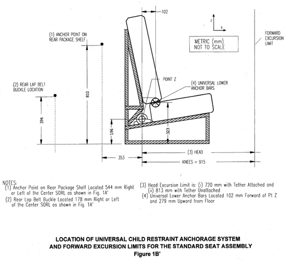
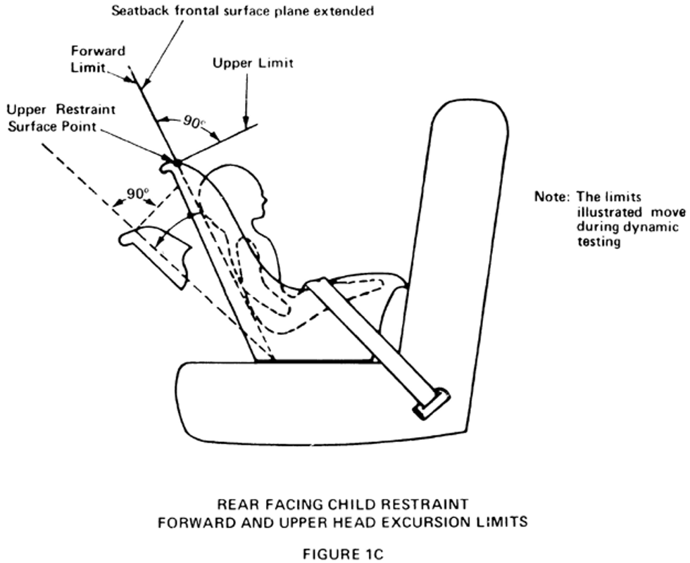
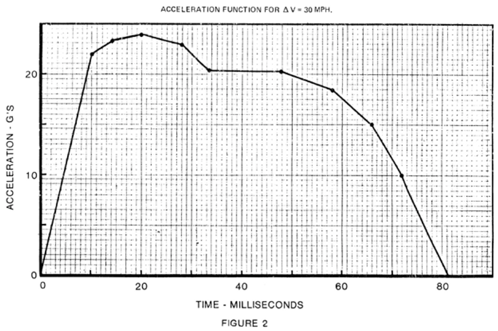
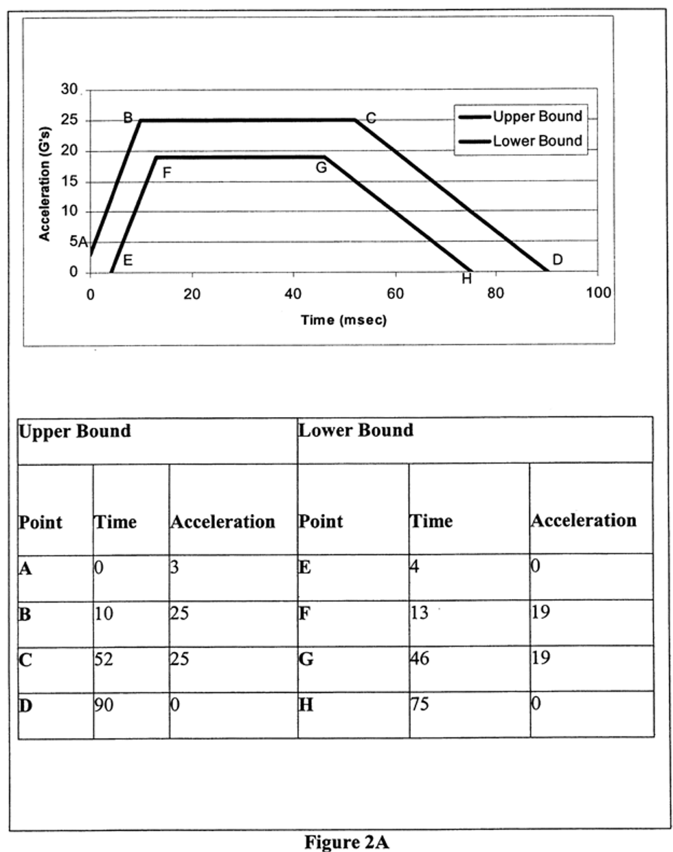
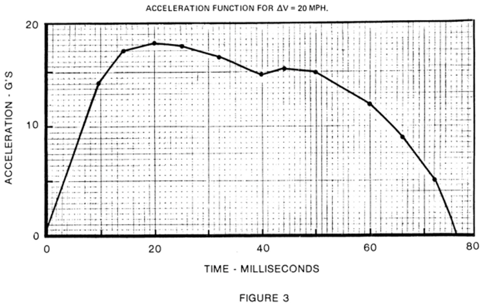
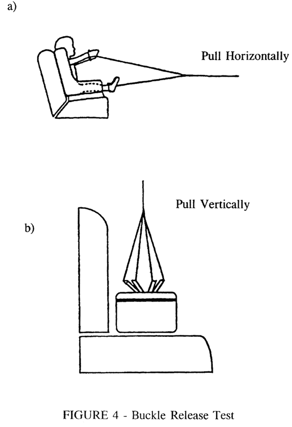
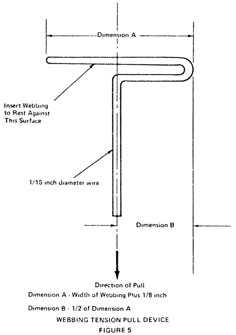
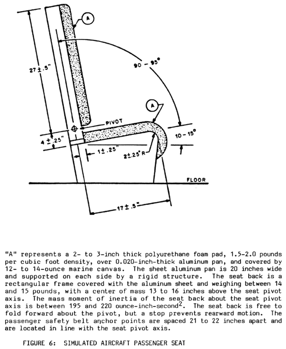
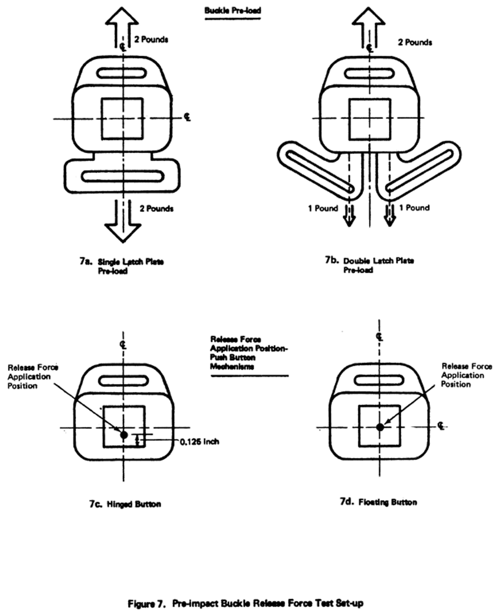
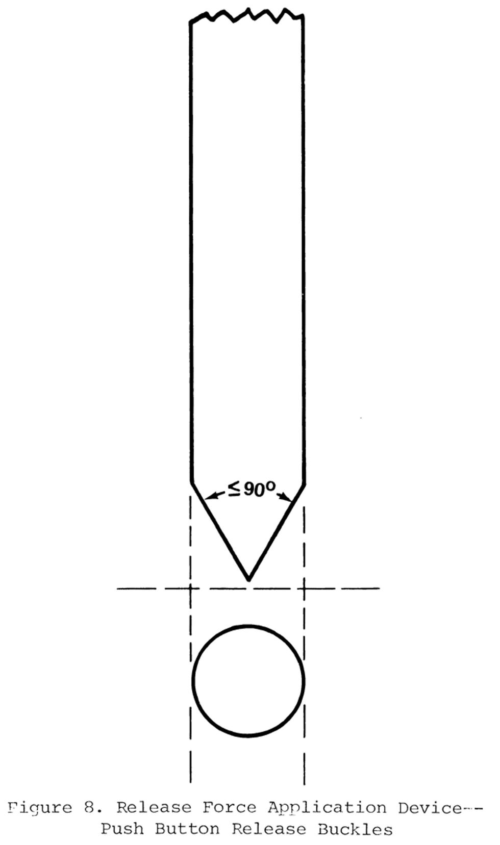
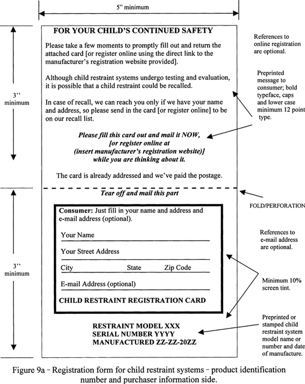
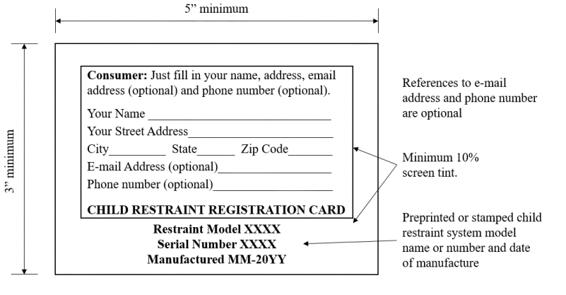
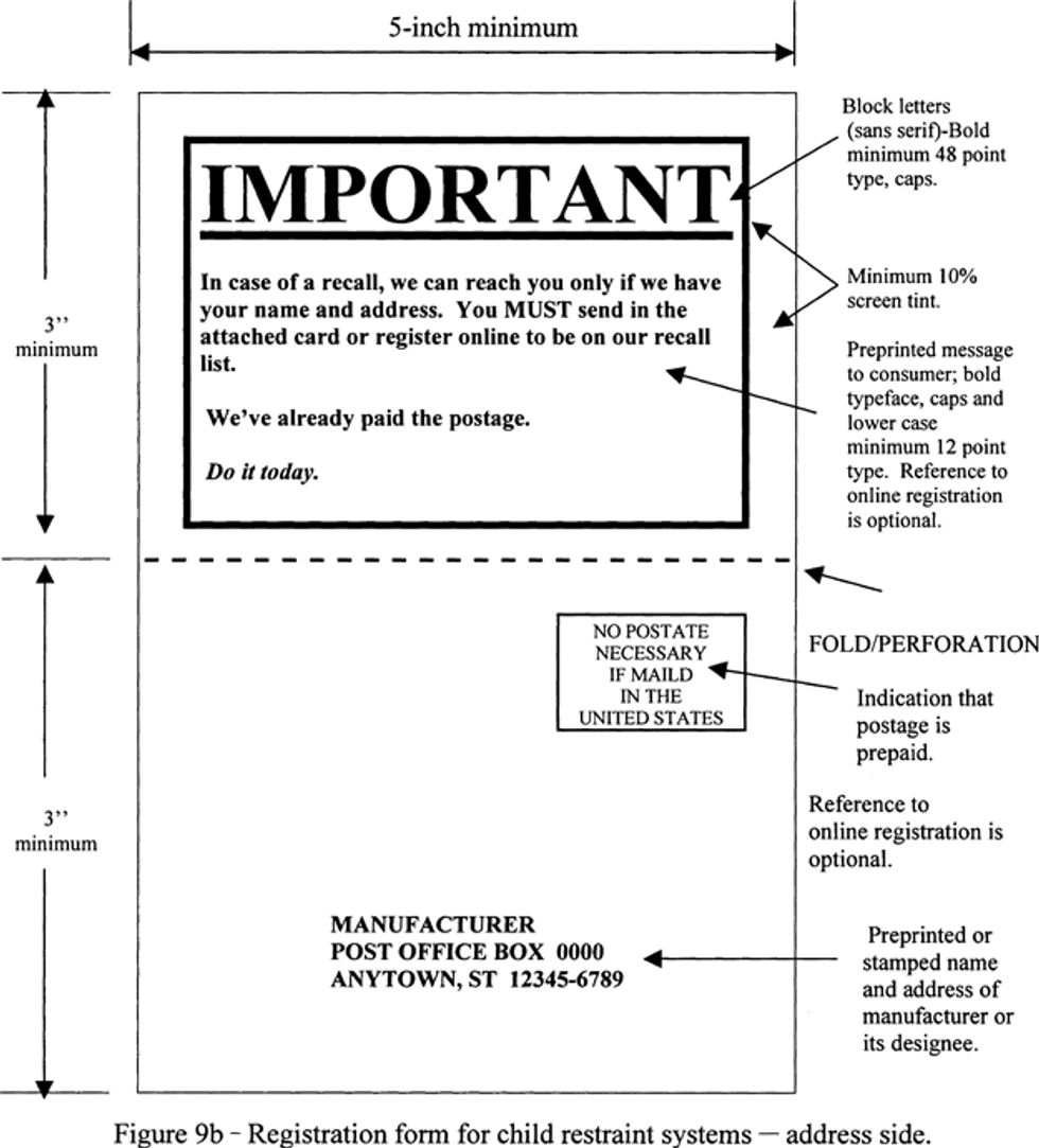
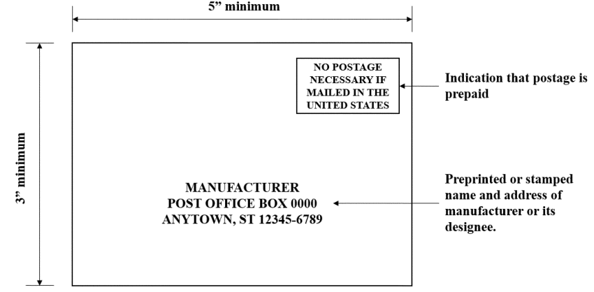
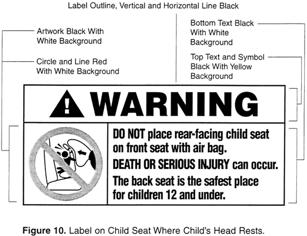
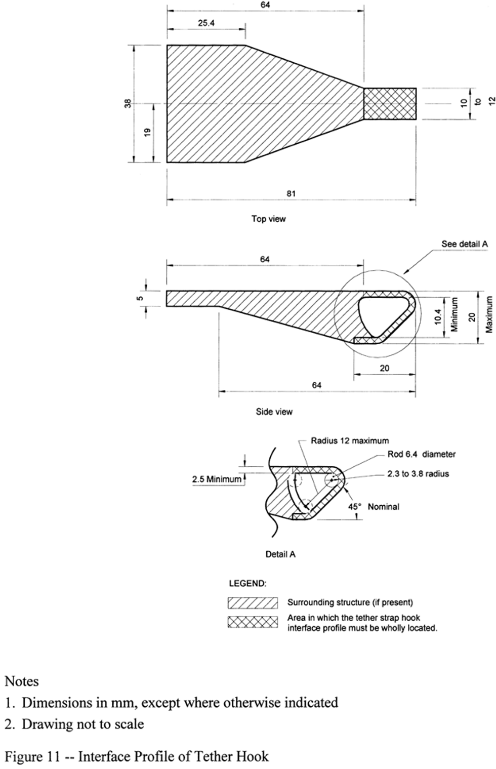
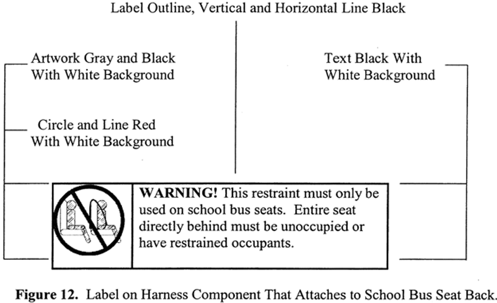
S10.2.3Hybrid III 6-year-old in belt-positioning seats, Hybrid III weighted 6-year-old in belt-positioning seats, and Hybrid III 10-year-old in belt-positioning seats. When using the Hybrid III 6-year-old (part 572, subpart N), the Hybrid III weighted 6-year-old (part 572, subpart S), or the Hybrid III 10-year-old (part 572, subpart T) in belt-positioning seats, position the dummy in accordance with S5.6.1 or S5.6.2, while conforming to the following:
(a)Prepare the dummy.
(1) When using the Hybrid III 10-year-old dummy, prepare the dummy according to the following:
(i) Set the dummy’s neck angle at the SP-16 setting (“SP” means standard procedure), see Figure 14a.
(ii) Set the dummy’s lumbar angle at the SP-12 setting, see Figure 14b. This is done by aligning the notch on the lumbar adjustment bracket with the SP-12 notch on the lumbar attachment.
(iii) Adjust the limb joints to 1-2 g while the torso is in the seated position.
(iv) Apply double-sided tape to the surface of a lap shield, which is a piece of translucent silicone rubber 3 mm 0.5 mm thick (50A durometer) cut to the dimensions specified in Figure 13. Place the lap shield on the pelvis of the dummy. Align the top of the lap shield with the superior anterior edge of the pelvis skin. Attach the lap shield to the dummy.
(v) Apply double-sided tape to one side of a pelvis positioning pad, which is a 125 x 95 x 20 mm (+/-2 mm tolerance in each of the three dimensions) piece of closed cell (Type 2 according to ASTM D-1056-07) (incorporated by reference; see§571.5 ) foam or rubber cut from material having the following specifications: compression resistance between 9 to 17 psi in a compression-deflection test specified in ASTM D-1056-07 (incorporated by reference; see§571.5 ), and a density of 7 to 12.5 lb/ft3. Center the long axis of the pad on the posterior of the pelvis with the top edge of the foam aligned with the superior edge of the pelvis skin. Attach the pelvis positioning pad to the dummy.
(a)(1)(vi) Dress and prepare the dummy according to S9.
(a)(2) When using the Hybrid III 6-year-old dummy, prepare the dummy according to the following:
(a)(2)(i) If necessary, adjust the limb joints to 1-2 g while the torso is in the seated position.
(a)(2)(ii) Apply double-sided tape to the surface of a lap shield, which is a piece of translucent silicone rubber 3 mm thick ±0.5 mm thick (50A durometer) cut to the dimensions specified in Figure 13. Place the lap shield on the pelvis of the dummy. Align the top of the lap shield with the superior anterior edge of the pelvis skin. Attach the lap shield to the dummy.
(a)(2)(iii) Dress and prepare the dummy according to S9.
(b) Position the belt-positioning seat according to S6.1.2(a)(1)(ii).
(c) Position the dummy in the belt-positioning seat.
(c)(1) Place the dummy on the seat cushion of the belt-positioning seat such that the plane of the posterior pelvis is parallel to the plane of the seat back of the belt-positioning seat, standard seat assembly or vehicle seat back, but not touching. Pick up and move the dummy rearward, maintaining the parallel planes, until the pelvis positioning pad, if used, or the pelvis or back of the dummy and the back of the belt-positioning seat or the back of the standard seat assembly, are in minimal contact.
(c)(2) Straighten and align the arm segments horizontally, then rotate the arms upward at the shoulder as far as possible without contacting the belt-positioning seat. Straighten and align the legs horizontally and extend the lower legs as far as possible in the forward horizontal direction, with the feet perpendicular to the centerline of the lower legs.
(c)(3) Using a flat square surface with an area of 2580 square millimeters, apply a force of 178 N (40 lb) first against the dummy crotch and then against the dummy thorax on the midsagittal plane of the dummy, perpendicular to:
(c)(3)(i) The plane of the back of the belt-positioning seat, in the case of a belt-positioning seat with a back, or,
(c)(3)(ii) The plane of the back of the standard seat assembly or vehicle seat, in the case of a backless belt-positioning seat or built-in booster.
(c)(4) Rotate the arms of the dummy down so that they are perpendicular to the torso.
(c)(5) Bend the knees until the back of the lower legs are in minimal contact with the belt-positioning seat, standard seat assembly or vehicle seat. Position the legs such that the outer edges of the knees are 180 +/- 10 mm apart for the Hybrid III 6-year-old dummy and 220 +/- 10 mm apart for the Hybrid III 10-year-old dummy. Position the feet such that the soles are perpendicular to the centerline of the lower legs. In the case of a belt-positioning seat with a back, adjust the dummy so that the shoulders are parallel to a line connecting the shoulder belt guides. This can be accomplished by leaning the torso such that the dummy’s head and neck are centered on the backrest components of the belt-positioning seat. In case of a backless child restraint, adjust the dummy’s torso so that the head is as close to laterally level as possible.
(d)Apply the belt. Attach the vehicle belts and tighten them as specified in S6.1.2.
(e)Dummy final positioning.
(e)(1) Check the leg, feet, thorax and head positions and make any necessary adjustments to achieve the positions described in S10.2.3(c)(5). Position the legs, if necessary, so that the leg placement does not inhibit thorax movement in tests conducted under S6.
(e)(2) Rotate each dummy arm downwards in the plane parallel to the dummy’s midsagittal plane until the arm contacts a surface of the child restraint system or the standard seat assembly, in the case of an add-on system, or the specific vehicle shell or specific vehicle, in the case of a built-in system, as appropriate. Position the arms, if necessary, so that the arm placement does not inhibit torso or head movement in tests conducted under S6.
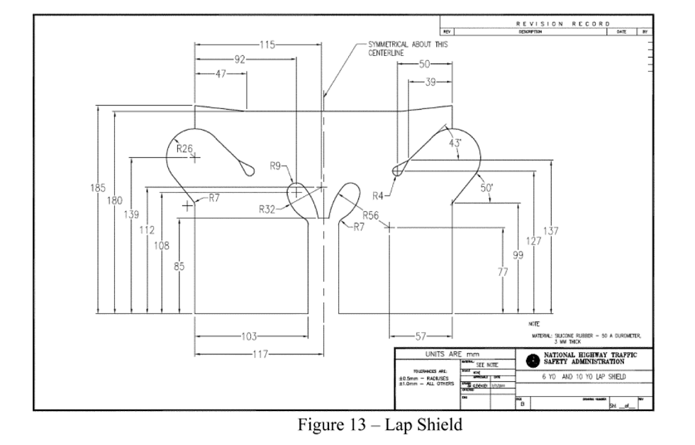
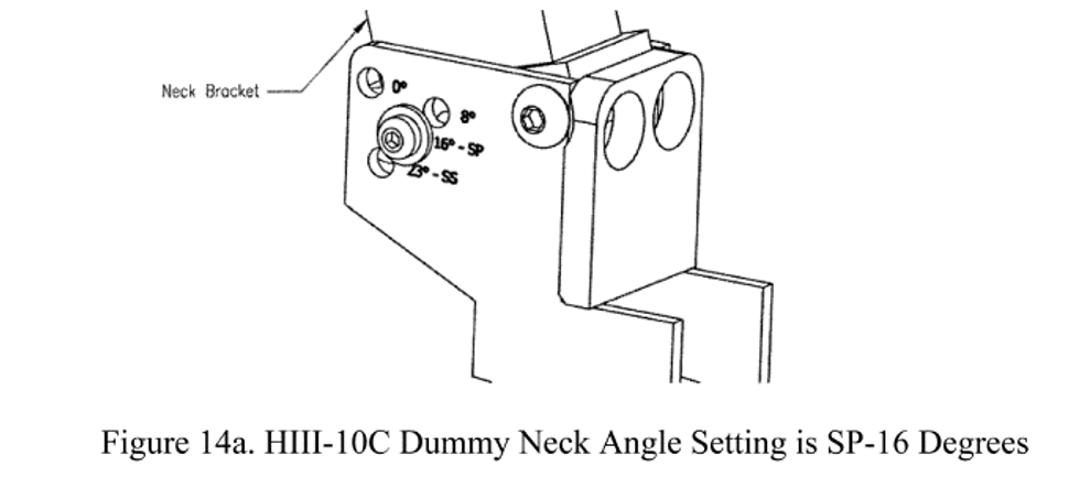
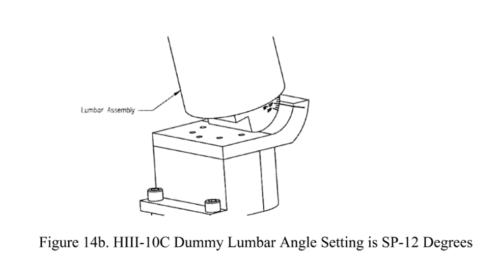
EDITORIAL NOTE: ForFederal Register citations affecting§571.213, see the List of CFR Sections Affected in the Finding Aids section of this volume.


This final rule amends a Federal Motor Vehicle Safety Standard (FMVSS) regarding child restraint systems. The amendments, mandatory in one year, modernize the standard by, among other things, updating CRS owner registration program requirements, labeling requirements on correctly using child restraints, requirements for add-on school bus-specific child restraint systems, and provisions for NHTSA's use of test dummies in NHTSA compliance tests. Amendments mandatory in three years include adding a new FMVSS that updates to standard seat assemblies on which NHTSA tests child restraint systems for compliance with frontal crash performance requirements. This final rule fulfills a mandate of the Moving Ahead for Progress in the 21st Century Act (MAP–21) that directs NHTSA to update the standard seat assembly. The purpose of this final rule is to ensure continued effectiveness of child restraint systems in current and future vehicles.
DATES:
Effective date: February 5, 2024.
IBR date: The incorporation by reference of certain publications listed in the rule is approved by the Director of the Federal Register as of February 5, 2024. The incorporation by reference of certain other publications listed in the rule was approved by the Director as of February 6, 2012.
Compliance date: The compliance date for the amendments to FMVSS No. 213 is December 5, 2024. The compliance date for meeting FMVSS No. 213b is December 5, 2026. Optional early compliance with the standards is permitted.
Reconsideration date: If you wish to petition for reconsideration of this rule, your petition must be received by January 19, 2024.
Published in theFederal Register December 5, 2023, page 84514.
| §571.5 Matter incorporated by reference. | ||
| (b)(3) | Added | View text |
| (d)(16) | Revised | View text |
| (d)(22)-(d)(39) | Redesignated | View text |
| (k)(6)-(7) | Added | View text |
| (l)(3)-(4) | Revised | View text |
| §571.213 Child restraint systems; Applicable unless a vehicle or child restraint system is certified to §571.213b. | ||
| Entire section | Revised | View text |
| §571.213b Standard No. 213b; Child restraint systems; Mandatory applicability beginning | ||
| Entire section | Added | View text |
New Text
§571.5 Matter incorporated by reference.
* * * *
(d)(16) ASTM D1056-07, Standard Specification for Flexible Cellular Materials-Sponge or Expanded Rubber, approved March 1, 2007; into§§571.213;571.213b.
* * * *
(l)(3) SAE Recommended Practice J211, Instrumentation for Impact Tests, revised June 1980; into §571.218.
(l)(4) SAE Recommended Practice J211/1, Instrumentation for Impact Tests—Part 1— Electronic Instrumentation; revised March 1995;§§571.202a;571.208;571.213;571.213a;571.213b;571.218;571.403.
§571.213 Child restraint systems; Applicable unless a vehicle or child restraint system is certified to § 571.213b.
S1.Scope. This standard specifies requirements for child restraint systems used in motor vehicles and aircraft.
S2.Purpose. The purpose of this standard is to reduce the number of children killed or injured in motor vehicle crashes and in aircraft.
S3.Application. This standard applies to passenger cars, multipurpose passenger vehicles, trucks and buses, and to child restraint systems for use in motor vehicles and aircraft, manufactured before December 5, 2026. FMVSS No. 213b applies to child restraint systems manufactured on or after December 5, 2026.
S4.Definitions.
Add-on child restraint system
means any portable child restraint system.
Backless child restraint system
means a child restraint, other than a belt-positioning seat, that consists of a seating platform that does not extend up to provide a cushion for the child’s back or head and has a structural element designed to restrain forward motion of the child’s torso in a forward impact.
Belt-positioning seat
means a child restraint system that positions a child on a vehicle seat to improve the fit of a vehicle Type II belt system on the child and that lacks any component, such as a belt system or a structural element, designed to restrain forward movement of the child’s torso in a forward impact.
Booster seat
means either a backless child restraint system or a belt-positioning seat.
Built-in child restraint system
means a child restraint system that is designed to be an integral part of and permanently installed in a motor vehicle.
Car bed
means a child restraint system designed to restrain or position a child in the supine or prone position on a continuous flat surface.
Child restraint anchorage system
is defined in S3 of FMVSS No. 225 (§571.225).
Child restraint system
means any device, except Type I or Type II seat belts, designed for use in a motor vehicle or aircraft to restrain, seat, or position children who weigh 36 kilograms (kg) (80 lb) or less.
Contactable surface
means any child restraint system surface (other than that of a belt, belt buckle, or belt adjustment hardware) that may contact any part of the head or torso of the appropriate test dummy, specified in S7, when a child restraint system is tested in accordance with S6.1.
Factory-installed built-in child restraint system
means a built-in child restraint system that has been or will be permanently installed in a motor vehicle before that vehicle is certified as a completed or altered vehicle in accordance with part 567 of this chapter.
Harness
means a combination pelvic and upper torso child restraint system that consists primarily of flexible material, such as straps, webbing or similar material, and that does not include a rigid seating structure for the child.
Rear-facing child restraint system
means a child restraint system, except a car bed, that positions a child to face in the direction opposite to the normal direction of travel of the motor vehicle.
Representative aircraft passenger seat
means either a Federal Aviation Administration approved production aircraft passenger seat or a simulated aircraft passenger seat conforming to Figure 6.
School bus child restraint system means an add-on child restraint system (including a harness) manufactured and sold only for use on school bus seats, that has a label conforming with S5.3.1(b). (This definition applies to child restraint systems manufactured on or after December 5, 2024.)
Seat orientation reference line or SORL
means the horizontal line through Point Z as illustrated in Figure 1A.
Specific vehicle shell
means the actual vehicle model part into which the built-in child restraint system is or is intended to be fabricated, including the complete surroundings of the built-in system. If the built-in child restraint system is or is intended to be fabricated as part of any seat other than a front seat, these surroundings include the back of the seat in front, the interior rear side door panels and trim, the floor pan, adjacent pillars (e.g., the B and C pillars), and the ceiling. If the built-in system is or is intended to be fabricated as part of the front seat, these surroundings include the dashboard, the steering mechanism and its associated trim hardware, any levers and knobs installed on the floor or on a console, the interior front side door panels and trim, the front seat, the floor pan, the A pillars and the ceiling.
Tether anchorage
is defined in S3 of FMVSS No. 225 (§571.225).
Tether strap
is defined in S3 of FMVSS No. 225 (§571.225).
Tether hook
is defined in S3 of FMVSS No. 225 (§571.225).
Torso
means the portion of the body of a seated anthropomorphic test dummy, excluding the thighs, that lies between the top of the child restraint system seating surface and the top of the shoulders of the test dummy.
S5.Requirements.(a) Each motor vehicle with a built-in child restraint system shall meet the requirements in this section when, as specified, tested in accordance with S6.1 and this paragraph.
(b) Each child restraint system manufactured for use in motor vehicles shall meet the requirements in this section when, as specified, tested in accordance with S6.1 and this paragraph. Each add-on system shall meet the requirements at each of the restraint’s seat back angle adjustment positions and restraint belt routing positions, when the restraint is oriented in the direction recommended by the manufacturer (e.g., forward, rearward or laterally) pursuant to S5.6, and tested with the test dummy specified in S7.
(c) Each child restraint system manufactured for use in aircraft shall meet the requirements in this section and the additional requirements in S8.
(d) Each child restraint tested with a Part 572 Subpart S dummy need not meet S5.1.2 and S5.1.3.
(e) Each child restraint system tested with a part 572 subpart T dummy need not meet S5.1.2.1(a).
(f) Each child restraint system that is equipped with an internal harness or other internal components to restrain the child need not meet this standard when attached to the lower anchors of the child restraint anchorage system on the standard seat assembly if the sum of the weight of the child restraint system (in pounds) and the average weight of child represented by the test dummy used to test the child restraint in accordance with S7 of this standard, shown in the table below, exceeds 65 pounds. Such a child restraint must meet this standard when tested using its internal harness or components to restrain such a test dummy while installed using the standard seat belt assembly specified in S5.3.2 of this standard.
| Test dummy (specified in S7 of this standard) | Average weight of child represented by test dummy (pounds) |
| CRABI 12-month-old infant dummy (49 CFR Part 572, Subpart R) | 22 |
| Hybrid III 3-year-old dummy(49 CFR Part 572, Subpart P) | 31 |
| Hybrid III 6-year-old dummy 49 CFR Part 572, Subpart N) | 45 |
| Hybrid III 6-year-old weighted child test dummy (49 CFR Part 572 Subpart S) | 62 |
| Hybrid II 6-year-old dummy (49, CFR Part 572, Subpart I) | 45 |
(g) Each add-on child restraint system manufactured for use in motor vehicles, that is recommended for children in a weight range that includes weights up to 18 kilograms (40 pounds), or for children in a height range that includes heights up to 1100 millimeters, shall meet the requirements in this standard and the additional side impact protection requirements in Standard No. 213a (§571.213a). Excepted from Standard No. 213a are harnesses and car beds.
S5.1Dynamic performance.
S5.1.1Child restraint system integrity. When tested in accordance with S6.1, each child restraint system shall meet the requirements of paragraphs (a) through (c) of this section.
(a) Exhibit no complete separation of any load bearing structural element and no partial separation exposing either surfaces with a radius of less than 1⁄ 4 inch or surfaces with protrusions greater than 3⁄ 8 inch above the immediate adjacent surrounding contactable surface of any structural element of the system.
(b)(1) If adjustable to different positions, remain in the same adjustment position during the testing that it was in immediately before the testing, except as otherwise specified in paragraph (b)(2).
(2)(i) Subject to paragraph (b)(2)(ii), a rear-facing child restraint system may have a means for repositioning the seating surface of the system that allows the system’s occupant to move from a reclined position to an upright position and back to a reclined position during testing.
(ii) No opening that is exposed and is larger than 1⁄ 4 inch before the testing shall become smaller during the testing as a result of the movement of the seating surface relative to the restraint system as a whole.
(c) If a front facing child restraint system, not allow the angle between the system’s back support surfaces for the child and the system’s seating surface to be less than 45 degrees at the completion of the test.
S5.1.2Injury criteria. When tested in accordance with S6.1 and with the test dummies specified in S7, each child restraint system manufactured before August 1, 2005, that, in accordance with S5.5.2, is recommended for use by children whose mass is more than 10 kg shall—
(a) Limit the resultant acceleration at the location of the accelerometer mounted in the test dummy head as specified in part 572 such that the expression:
shall not exceed 1,000, where a is the resultant acceleration expressed as a multiple of g (the acceleration of gravity), and t 1 and t 2 are any two moments during the impacts.
(b) Limit the resultant acceleration at the location of the accelerometer mounted in the test dummy upper thorax as specified in part 572 to not more than 60 g’s, except for intervals whose cumulative duration is not more than 3 milliseconds.
S5.1.2.1 When tested in accordance with S6.1 and with the test dummies specified in S7, each child restraint system manufactured on or after August 1, 2005 shall’
(a) Limit the resultant acceleration at the location of the accelerometer mounted in the test dummy head such that, for any two points in time, t1 and t2, during the event which are separated by not more than a 36 millisecond time interval and where t1 is less than t2, the maximum calculated head injury criterion (HIC36 ) shall not exceed 1,000, determined using the resultant head acceleration at the center of gravity of the dummy head, ar, expressed as a multiple of g (the acceleration of gravity), calculated using the expression:
(b) The resultant acceleration calculated from the output of the thoracic instrumentation shall not exceed 60 g’s, except for intervals whose cumulative duration is not more than 3 milliseconds.
S5.1.2.2 At the manufacturer’s option (with said option irrevocably selected prior to, or at the time of, certification of the restraint), child restraint systems manufactured before August 1, 2005 may be tested to the requirements of S5 while using the test dummies specified in S7.1.2 of this standard according to the criteria for selecting test dummies specified in that paragraph. That paragraph specifies the dummies used to test child restraint systems manufactured on or after August 1, 2005. If a manufacturer selects the dummies specified in S7.1.2 to test its product, the injury criteria specified by S5.1.2.1 of this standard must be met. Child restraints manufactured on or after August 1, 2005 must be tested using the test dummies specified in S7.1.2.
S5.1.3Occupant excursion. When tested in accordance with S6.1 and the requirements specified in this section, each child restraint system shall meet the applicable excursion limit requirements specified in S5.1.3.1-S5.1.3.3.
S5.1.3.1Child restraint systems other than rear-facing ones and car beds. Each child restraint system, other than a rear-facing child restraint system or a car bed, shall retain the test dummy’s torso within the system.
(a) For each add-on child restraint system:
(1) No portion of the test dummy’s head shall pass through a vertical transverse plane that is 720 mm or 813 mm (as specified in the table in this S5.1.3.1) forward of point Z on the standard seat assembly, measured along the center SORL (as illustrated in figure 1B of this standard); and
(2) Neither knee pivot point shall pass through a vertical transverse plane that is 915 mm forward of point Z on the standard seat assembly, measured along the center SORL.
| When this type of child restraint | Is tested in accordance with— | These excursion limits apply | Explanatory note: in the test specified in 2nd column, the child restraint is attached to the test seat assembly in the manner described below, subject to certain conditions |
|---|---|---|---|
| Harnesses and restraints designed for use by children with physical disabilities | S6.1.2(a)(1)(i)(A) | Head 813 mm; Knee 915 mm | Attached with lap belt; in addition, if a tether is provided, it is attached. |
| Harnesses labeled per S5.3.1(b)(i) through S5.3.1(b)(iii) and Figure 12 | S6.1.2(a)(1)(i)(A) | Head 813 mm; Knee 915 mm | Attached with seat back mount. |
| Belt-positioning seats | S6.1.2(a)(1)(ii) | Head 813 mm; Knee 915 mm | Attached with lap and shoulder belt; no tether is attached. |
| All other child restraints (i.e., other than harnesses, restraints designed for use by children with physical disabilities, harnesses manufactured exclusively for school buses, and belt-positioning seats) | S6.1.2(a)(1)(i)(B) | Head 813 mm; Knee 915 mm | Attached with a lap belt, without a tether attached; and, Attached to lower anchorages of a child restraint anchorage system; no tether is attached. |
| All other child restraints (i.e., other than harnesses, restraints designed for use by children with physical disabilities, harnesses labeled per S5.3.1(b)(i) through S5.3.1(b)(iii) and Figure 12, and belt-positioning seats) | S6.1.2(a)(1)(i)(A), S6.1.2(a)(1)(i)(C) | Head 720 mm; Knee 915 mm | Attached with a lap belt, with a tether attached; and, Attached to lower anchorages of child restraint anchorage system, with a tether attached. |
| When this type of child restraint | Is tested in accordance with— | These excursion limits apply | Explanatory note: in the test specified in 2nd column, the excursion requirement must be met when the child restraint system is attached to the test seat assembly in the manner described below, subject to certain conditions |
|---|---|---|---|
| Harnesses and restraints designed for use by children with physical disabilities | S6.1.2(a)(1)(i)(A) | Head 813 mm; Knee 915 mm | Attached with lap and shoulder belt; in addition, if a tether is provided, it is attached. |
| School bus child restraint systems | S6.1.2(a)(1)(i)(A) | Head 813 mm; Knee 915 mm | Attached with seat back mount, or, seat back, and, seat pan mounts. |
| Booster seats | S6.1.2(a)(1)(ii) | Head 813 mm; Knee 915 mm | Attached with lap and shoulder belt; no tether is attached. |
| Child restraints other than harnesses, restraints designed for use by children with physical disabilities, school bus child restraint systems, and booster seats | S6.1.2(a)(1)(i)(B) | Head 813 mm; Knee 915 mm | Attached with a lap belt; without a tether attached. Attached to lower anchorages of child restraint anchorage system; with no tether attached. |
| Child restraints other than harnesses, restraints designed for use by children with physical disabilities, and school bus child restraint systems | S6.1.2(a)(1)(i)(A), S6.1.2(a)(1)(i)(C) | Head 720 mm; Knee 915 mm | Attached with a lap belt, with a tether attached. Attached to lower anchorages of child restraint anchorage system, with a tether attached. |
| Child restraints equipped with a fixed or movable surface described in S5.2.2.2 that has belts that are not an integral part of that fixed or movable surface | S6.1.2(a)(2) | Head 813 mm; Knee 915 mm | Attached with lap belt, no tether is attached. |
(b) In the case of a built-in child restraint system, neither knee pivot point shall, at any time during the dynamic test, pass through a vertical transverse plane that is 305 mm forward of the initial pre-test position of the respective knee pivot point, measured along a horizontal line that passes through the knee pivot point and is parallel to the vertical longitudinal plane that passes through the vehicle’s longitudinal centerline.
S5.1.3.2Rear-facing child restraint systems. In the case of each rear-facing child restraint system, all portions of the test dummy’s torso shall be retained within the system and neither of the target points on either side of the dummy’s head and on the transverse axis passing through the center of mass of the dummy’s head and perpendicular to the head’s midsagittal plane, shall pass through the transverse orthogonal planes whose intersection contains the forward-most and top-most points on the child restraint system surfaces (illustrated in Figure 1C).
S5.1.3.3Car beds. In the case of car beds, all portions of the test dummy’s head and torso shall be retained within the confines of the car bed.
S5.1.4Back support angle. When a rear-facing child restraint system is tested in accordance with S6.1, the angle between the system’s back support surface for the child and the vertical shall not exceed 70 degrees.
S5.2Force distribution.
S5.2.1Minimum head support surface—child restraints other than car beds.
S5.2.1.1 Except as provided in S5.2.1.2, each child restraint system other than a car bed shall provide restraint against rearward movement of the head of the child (rearward in relation to the child) by means of a continuous seat back which is an integral part of the system and which—
(a) Has a height, measured along the system seat back surface for the child in the vertical longitudinal plane passing through the longitudinal centerline of the child restraint systems from the lowest point on the system seating surface that is contacted by the buttocks of the seated dummy, as follows:
| Weight1 | Height2 (mm) |
|---|---|
| Not more than 18 kg........................................ | 500 |
| More than 18 kg............................................... | 560 |
1 When a child restraint system is recommended under S5.5 for use by children of the above weights.
2 The height of the portion of the system seat back providing head restraint shall not be less than the above.
(b) Has a width of not less than 8 inches, measured in the horizontal plane at the height specified in paragraph (a) of this section. Except that a child restraint system with side supports extending at least 4 inches forward from the padded surface of the portion of the restraint system provided for support of the child’s head may have a width of not less than 6 inches, measured in the horizontal plane at the height specified in paragraph (a) of this section.
(c) Limits the rearward rotation of the test dummy head so that the angle between the head and torso of the dummy specified in S7. when tested in accordance with S6.1 is not more than 45 degrees greater than the angle between the head and torso after the dummy has been placed in the system in accordance with S6.1.2.3 and before the system is tested in accordance with S6.1.
S5.2.1.2 The applicability of the requirements of S5.2.1.1 to a front-facing child restraint, and the conformance of any child restraint other than a car bed to those requirements, is determined using the largest of the test dummies specified in S7 for use in testing that restraint, provided that the 6-year-old dummy described in subpart I or subpart N of part 572 of this title and the 10-year-old dummy described in subpart T of part 572 of this title, are not used to determine the applicability of or compliance with S5.2.1.1. A front facing child restraint system is not required to comply with S5.2.1.1 if the target point on either side of the dummy's head is below a horizontal plane tangent to the top of—
(a) The standard seat assembly, in the case of an add-on child restraint system, when the dummy is positioned in the system and the system is installed on the assembly in accordance with S6.1.2.
(b) The vehicle seat, in the case of a built-in child restraint system, when the system is activated and the dummy is positioned in the system in accordance with S6.1.2.
S5.2.2Torso impact protection. Each child restraint system other than a car bed shall comply with the applicable requirements of S5.2.2.1 and S5.2.2.2.
S5.2.2.1(a) The system surface provided for the support of the child’s back shall be flat or concave and have a continuous surface area of not less than 85 square inches.
(b) Each system surface provided for support of the side of the child’s torso shall be flat or concave and have a continuous surface of not less than 24 square inches for systems recommended for children weighing 20 pounds or more, or 48 square inches for systems recommended for children weighing less than 20 pounds.
(c) Each horizontal cross section of each system surface designed to restrain forward movement of the child’s torso shall be flat or concave and each vertical longitudinal cross section shall be flat or convex with a radius of curvature of the underlying structure of not less than 2 inches.
S5.2.2.2 Each forward-facing child restraint system shall have no fixed or movable surface—
(a) Directly forward of the dummy and intersected by a horizontal line—
(1) Parallel to the SORL, in the case of the add-on child restraint system, or
(2) Parallel to a vertical plane through the longitudinal center line of the vehicle seat, in the case of a built-in child restraint system, and,
(b) Passing through any portion of the dummy, except for surfaces which restrain the dummy when the system is tested in accordance with S6.1.2(a)(2), so that the child restraint system shall conform to the requirements of S5.1.2 and S5.1.3.1.
S5.2.3 [Reserved]
S5.2.4Protrusion limitation. Any portion of a rigid structural component within or underlying a contactable surface, or any portion of a child restraint system surface that is subject to the requirements of S5.2.3 shall, with any padding or other flexible overlay material removed, have a height above any immediately adjacent restraint system surface of not more than3/8 inch and no exposed edge with a radius of less than1/4 inch.
S5.3Installation.
S5.3.1 Add-on child restraints shall meet either (a) or (b), as appropriate.
(a) Except for components designed to attach to a child restraint anchorage system, each add-on child restraint system must not have any means designed for attaching the system to a vehicle seat cushion or vehicle seat back and any component (except belts) that is designed to be inserted between the vehicle seat cushion and vehicle seat back.
(b) School bus child restraint systems (including harnesses manufactured for use on school bus seats) must have a label that conforms in content to Figure 12 and to the requirements of S5.3.1(b)(1) through S5.3.1(b)(3) of this standard. The label must be permanently affixed to the part of the school bus child restraint system, that attaches the system to a vehicle seat back.
(1) The label must be plainly visible when installed and easily readable.
(2) The message area must be white with black text. The message area must be no less than 20 square centimeters.
(3) The pictogram shall be gray and black with a red circle and slash on a white background. The pictogram shall be no less than 20 mm in diameter.
(c) The provision that add-on child restraint systems shall meet the requirements of this standard when installed solely by a Type 1 belt applies to child restraint systems manufactured before September 1, 2029. Except for harnesses, the requirement sunsets for child restraint systems manufactured on or after September 1, 2029. For harnesses, the requirement does not sunset and continues to apply to harnesses manufactured on or after September 1, 2029.
S5.3.2 Each add-on child restraint system shall be capable of meeting the requirements of this standard when installed solely by each of the means indicated in the following table for the particular type of child restraint system:
| Type of add-on child restraint system | Means of installation | ||||
|---|---|---|---|---|---|
| Type 1 seat belt assembly | Type 1 seat belt assembly plus a tether anchorage, if needed | Child restraint anchorage system (effective September 1, 2002) | Type II seat belt assembly | Seat back mount | |
| Harnesses labeled per S5.3.1(b)(1) through S5.3.1(b)(3) and Figure 12 | X | ||||
| Other harnesses | X | ||||
| Car beds | X | ||||
| Rear-facing restraints | X | X | |||
| Belt-positioning seats | X | ||||
| All other child restraints | X | X | X | ||
S5.3.2.1 School bus child restraint systems manufactured on or after December 5, 2024, shall be capable of meeting the requirements of this standard when installed by seat back mount, or, seat back mount and seat pan mount.
S5.3.3Car beds. Each car bed shall be designed to be installed on a vehicle seat so that the car bed’s longitudinal axis is perpendicular to a vertical longitudinal plane through the longitudinal axis of the vehicle.
S5.4Belts, belt buckles, and belt webbing.
S5.4.1Performance requirements.
S5.4.1.1Child restraint systems manufactured before September 1, 2007. The webbing of belts provided with a child restraint system and used to attach the system to the vehicle or to restrain the child within the system shall—
(a) After being subjected to abrasion as specified in S5.1(d) or S5.3(c) of FMVSS 209 (§571.209 ), have a breaking strength of not less than 75 percent of the strength of the unabraded webbing when tested in accordance with S5.1(b) of FMVSS 209. A mass of 2.35 ±.05 kg shall be used in the test procedure in S5.1(d) of FMVSS 209 for webbing, including webbing used to secure a child restraint system to the tether and lower anchorages of a child restraint anchorage system, except that a mass of 1.5 ±.05 kg shall be used for webbing in pelvic and upper torso restraints of a belt assembly used in a child restraint system. The mass is shown as (B) in Figure 2 of FMVSS 209.
(b) Meet the requirements of S4.2 (e) and (f) of FMVSS No. 209 (§571.209 ); and
(c) If contactable by the test dummy torso when the system is tested in accordance with S6.1, have a width of not less than 11/2 inches when measured in accordance with S5.4.1.3.
S5.4.1.2Child restraint systems manufactured on or after September 1, 2007. The webbing of belts provided with a child restraint system and used to attach the system to the vehicle or to restrain the child within the system shall—
(a) Have a minimum breaking strength for new webbing of not less than 15,000 N in the case of webbing used to secure a child restraint system to the vehicle, including the tether and lower anchorages of a child restraint anchorage system, and not less than 11,000 N in the case of the webbing used to secure a child to a child restraint system when tested in accordance with S5.1 of FMVSS No. 209. Each value shall be not less than the 15,000 N and 11,000 N applicable breaking strength requirements, but the median value shall be used for determining the retention of breaking strength in paragraphs (b)(1), (c)(1), and (c)(2) of this section S5.4.1.2. ”New webbing” means webbing that has not been exposed to abrasion, light or micro-organisms as specified elsewhere in this section.
(b)(1) After being subjected to abrasion as specified in S5.1(d) or S5.3(c) of FMVSS 209 (§571.209 ), have a breaking strength of not less than 75 percent of the new webbing strength, when tested in accordance with S5.1(b) of FMVSS
(2) A mass of 2.35 ±.05 kg shall be used in the test procedure in S5.1(d) of FMVSS 209 for webbing, including webbing to secure a child restraint system to the tether and lower anchorages of a child restraint anchorage system, except that a mass of 1.5 ±.05 kg shall be used for webbing in pelvic and upper torso restraints of a belt assembly used in a child restraint system. The mass is shown as (B) in Figure 2 of FMVSS 209.
(c)(1) After exposure to the light of a carbon arc and tested by the procedure specified in S5.1(e) of FMVSS 209 (§571.209 ), have a breaking strength of not less than 60 percent of the new webbing, and shall have a color retention not less than No. 2 on the AATCC Gray Scale for Evaluating Change in Color (incorporated by reference, see§571.5 ).
(2) After being subjected to micro-organisms and tested by the procedures specified in S5.1(f) of FMVSS 209 (§571.209 ), shall have a breaking strength not less than 85 percent of the new webbing.
(d) If contactable by the test dummy torso when the system is tested in accordance with S6.1, have a width of not less than 11/2 inches when measured in accordance with S5.4.1.3.
S5.4.1.3Width test procedure. Condition the webbing for 24 hours in an atmosphere of any relative humidity between 48 and 67 percent, and any ambient temperature between 70° and 77 °F. Measure belt webbing width under a tension of 5 pounds applied lengthwise.
S5.4.2Belt buckles and belt adjustment hardware. Each belt buckle and item of belt adjustment hardware used in a child restraint system shall conform to the requirements of S4.3(a) and S4.3(b) of FMVSS No. 209 (§571.209 ).
S5.4.3Belt Restraint.
S5.4.3.1General. Each belt that is part of a child restraint system and that is designed to restrain a child using the system shall be adjustable to snugly fit any child whose height and weight are within the ranges recommended in accordance with S5.5.2(f) and who is positioned in the system in accordance with the instructions required by S5.6.
S5.4.3.2Direct restraint. Except for belt-positioning seats, each belt that is part of a child restraint system and that is designed to restrain a child using the system and to attach the system to the vehicle, and each Type I and lap portion of a Type II vehicle belt that is used to attach the system to the vehicle shall, when tested in accordance with S6.1, impose no loads on the child that result from the mass of the system, or—
(a) In the case of an add-on child restraint system, from the mass of the seat back of the standard seat assembly specified in S6.1, or
(b) In the case of a built-in child restraint system, from the mass of any part of the vehicle into which the child restraint system is built.
S5.4.3.3Seating systems. Except for child restraint systems subject to S5.4.3.4, each child restraint system that is designed for use by a child in a seated position and that has belts designed to restrain the child, shall, with the test dummy specified in S7 positioned in the system in accordance with S10 provide:
(a) Upper torso restraint in the form of:
(i) Belts passing over each shoulder of the child, or
(ii) A fixed or movable surface that complies with S5.2.2.1(c), and
(b) Lower torso restraint in the form of:
(i) A lap belt assembly making an angle between 45° and 90° with the child restraint seating surface at the lap belt attachment points, or
(ii) A fixed or movable surface that complies with S5.2.2.1(c), and
(c) In the case of each seating system recommended for children whose masses are more than 10 kg, crotch restraint in the form of:
(i) A crotch belt connectable to the lap belt or other device used to restrain the lower torso, or
(ii) A fixed or movable surface that complies with S5.2.2.1(c).
S5.4.3.4Harnesses. Each child harness shall:
(a) Provide upper torso restraint, including belts passing over each shoulder of the child;
(b) Provide lower torso restraint by means of lap and crotch belt; and
(c) Prevent a child of any height for which the restraint is recommended for use pursuant to S5.5.2(f) from standing upright on the vehicle seat when the child is placed in the device in accordance with the instructions required by S5.6.
S5.4.3.5Buckle release. Any buckle in a child restraint system belt assembly designed to restrain a child using the system shall:
(a) When tested in accordance with S6.2.1 prior to the dynamic test of S6.1, not release when a force of less than 40 newtons (N) is applied and shall release when a force of not more than 62 N is applied;
(b) After the dynamic test of S6.1, when tested in accordance with the appropriate sections of S6.2, release when a force of not more than 71 N is applied, provided, however, that the conformance of any child restraint to this requirement is determined using the largest of the test dummies specified in S7 for use in testing that restraint when the restraint is facing forward, rearward, and/or laterally;
(c) Meet the requirements of S4.3(d)(2) of FMVSS No. 209 (§ 571.209 ), except that the minimum surface area for child restraint buckles designed for push button application shall be 0.6 square inch;
(d) Meet the requirements of S4.3(g) of FMVSS No. 209 (§ 571.209 ) when tested in accordance with S5.2(g) of FMVSS No. 209; and
(e) Not release during the testing specified in S6.1.
S5.5Labeling. Any labels or written instructions provided in addition to those required by this section shall not obscure or confuse the meaning of the required information or be otherwise misleading to the consumer. Any labels or written instructions other than in the English language shall be an accurate translation of English labels or written instructions.
S5.5.1 Each add-on child restraint system shall be permanently labeled with the information specified in S5.5.2 (a) through (m).
S5.5.2 The information specified in paragraphs (a) through (m) of this section shall be stated in the English language and lettered in letters and numbers that are not smaller than 10 point type. Unless otherwise specified, the information shall be labeled on a white background with black text. Unless written in all capitals, the information shall be stated in sentence capitalization.
(a) The model name or number of the system.
(b) The manufacturer’s name. A distributor’s name may be used instead if the distributor assumes responsibility for all duties and liabilities imposed on the manufacturer with respect to the system by the National Traffic and Motor Vehicle Safety Act, as amended.
(c) The statement: “Manufactured in ll,” inserting the month and year of manufacture.
(d) The place of manufacture (city and State, or foreign country). However, if the manufacturer uses the name of the distributor, then it shall state the location (city and State, or foreign country) of the principal offices of the distributor.
(e) The statement: “This child restraint system conforms to all applicable Federal motor vehicle safety standards.”
(f) For child restraint systems manufactured before December 5, 2024, paragraph (f)(1) of this section applies. For child restraint systems manufactured on or after December 5, 2024, paragraph (f)(2) of this section applies.
(1) One of the following statements, as appropriate, inserting the manufacturer's recommendations for the maximum mass of children who can safely occupy the system, except that booster seats shall not be recommended for children whose masses are less than 13.6 kg. For child restraint systems that can only be used as belt-positioning seats, manufacturers must include the maximum and minimum recommended height, but may delete the reference to weight:
(i) Use only with children who weigh __ pounds (__ kg) or less and whose height is (insert values in English and metric units; use of word “mass” in label is optional ) or less; or
(ii) Use only with children who weigh between __ and __ pounds (insert appropriate English and metric values; use of word “mass” is optional ) and whose height is (insert appropriate values in English and metric units ) or less and who are capable of sitting upright alone; or
(iii) Use only with children who weigh between __ and __ pounds (insert appropriate English and metric values; use of word “mass” is optional ) and whose height is (insert appropriate values in English and metric units ) or less.
(iv) Use only with children who weigh between __ and __ pounds (insert appropriate English and metric values; use of word “mass” is optional ) and whose height is between __ and __ (insert appropriate values in English and metric units ).
(2) For child restraint systems manufactured on or after December 5, 2024: Statements or a combination of statements and pictograms specifying the manufacturer's recommendations for the mass and height ranges (in English and metric units) of children who can safely occupy the system in each applicable mode (rear-facing, forward-facing, booster), except manufacturers shall not recommend forward-facing use for child restraint systems with internal harnesses for children of masses less than 12 kg (26.5 lb), and shall not recommend booster seats for children of masses less than 18.4 kg (40 lb).
(g) The statements specified in paragraphs (1) and (2):
(1) A heading as specified in S5.5.2(k)(3)(i), with the statement “WARNING! DEATH or SERIOUS INJURY can occur,” capitalized as written and followed by bulleted statements in the following order:
(i) As appropriate, the statements required by the following sections will be bulleted and placed after the statement required by 5.5.2(g)(1) in the following order: 5.5.2(k)(1), 5.5.2(h), 5.5.2(j), and 5.5.2(i). For child restraint systems manufactured on or after December 5, 2024, the statements required by 5.5.2(f) and 5.5.2(k)(2) need not be included.
(ii) Secure this child restraint with the vehicle's child restraint anchorage system, if available, or with a vehicle belt. [For car beds, harnesses, and belt positioning seats, the first part of the statement regarding attachment by the child restraint anchorage system is optional.] [For belt-positioning seats, the second part of the statement regarding attachment by the vehicle belt does not apply.] [For child restraints manufactured from February 27, 2014 to February 26, 2015, the following statement applies.] Child restraint systems equipped with internal harnesses to restrain the child and with components to attach to a child restraint anchorage system and for which the combined weight of the child restraint system and the maximum recommended child weight for use with internal harnesses exceeds 65 pounds, must be labeled with the following statement: “Do not use the lower anchors of the child restraint anchorage system (LATCH system) to attach this child restraint when restraining a child weighing more than * [*insert a recommended weight value in English and metric units such that the sum of the recommended weight value and the weight of the child restraint system does not exceed 65 pounds (29.5 kg)] with the internal harnesses of the child restraint.”
(iii) Follow all instructions on this child restraint and in the written instructions located (insert storage location on the restraint for the manufacturer’s installation instruction booklet or sheet ).
(iv) Register your child restraint with the manufacturer.
(2) At the manufacturer’s option, the phrase “DEATH or SERIOUS INJURY can occur” in the heading can be on either a white or yellow background.
(3) More than one label may be used for the required bulleted statements. Multiple labels shall be placed one above the other unless that arrangement is precluded by insufficient space or shape of the child restraint. In that case, multiple labels shall be placed side by side. When using multiple labels, the mandated warnings must be in the correct order when read from top to bottom. If the labels are side-by-side, then the mandated warnings must appear top to bottom of the leftmost label, then top to bottom of the next label to its right, and so on. There shall be no intervening labels and the required heading shall only appear on the first label in the sequence.
(h) In the case of each child restraint system that has belts designed to restrain children using them and which do not adjust automatically to fit the child: Snugly adjust the belts provided with this child restraint around your child.
(i)(1) For a booster seat that is recommended for use with either a vehicle’s Type I or Type II seat belt assembly, one of the following statements, as appropriate:
(i) Use only the vehicle’s lap and shoulder belt system when restraining the child in this booster seat; or,
(ii) Use only the vehicle’s lap belt system, or the lap belt part of a lap/ shoulder belt system with the shoulder belt placed behind the child, when restraining the child in this seat.
(2)(i) Except as provided in paragraph (i)(2)(ii) of this section, for a booster seat which is recommended for use with both a vehicle’s Type I and Type II seat belt assemblies, the following statement: Use only the vehicle’s lap belt system, or the lap belt part of a lap/shoulder belt system with the shoulder belt placed behind the child, when restraining the child with the (insert description of the system element provided to restrain forward movement of the child’s torso when used with a lap belt (e.g., shield )), and only the vehicle’s lap and shoulder belt system when using the booster without the (insert above description ).
(ii) A booster seat which is recommended for use with both a vehicle’s Type I and Type II seat belt assemblies is not subject to S5.5.2(i)(2)(i) if, when the booster is used with the shield or similar component, the booster will cause the shoulder belt to be located in a position other than in front of the child when the booster is installed. However, such a booster shall be labeled with a warning to use the booster with the vehicle’s lap and shoulder belt system when using the booster without a shield.
(j) In the case of each child restraint system equipped with a top anchorage strap, the statement: Secure the top anchorage strap provided with this child restraint.
(k) (1) In the case of each rear-facing child restraint system that is designed for infants only, the statement: Use only in a rear-facing position when using it in the vehicle.
(2) In the case of a child restraint system that is designed to be used rearward-facing for infants and forward-facing for older children, the statement: Use only in a rear-facing position when using it with an infant weighing less than (insert a recommended weight that is not less than 20 pounds ).
(3) Except as provided in (k)(4) of this section, each child restraint system that can be used in a rear-facing position shall have a label that conforms in content to Figure 10 and to the requirements of S5.5.2(k)(3)(i) through S5.5.2(k)(3)(iii) of this standard permanently affixed to the outer surface of the cushion or padding in or adjacent to the area where a child’s head would rest, so that the label is plainly visible and easily readable.
(i) The heading area shall be yellow with the word “warning” and the alert symbol in black.
(ii) The message area shall be white with black text. The message area shall be no less than 30 square cm.
(iii) The pictogram shall be black with a red circle and slash on a white background. The pictogram shall be no less than 30 mm in diameter.
(4) If a child restraint system is equipped with a device that deactivates the passenger-side air bag in a vehicle when and only when the child restraint is installed in the vehicle and provides a signal, for at least 60 seconds after deactivation, that the air bag is deactivated, the label specified in Figure 10 may include the phrase “unless air bag is off” after “on front seat with air bag.”
(l) An installation diagram showing the child restraint system installed in:
(1) A seating position equipped with a continuous-loop lap/shoulder belt;
(2) [Reserved]
(3) A seating position equipped with a child restraint anchorage system. For child restraint systems manufactured on or after February 27, 2015, the following paragraphs (l)(3)(i) and (ii) apply, as appropriate.
(i) If the child restraint system is designed to meet the requirements of this standard when installed by the child restraint anchorage system according to S5.3.2, and if the sum of the weight of the child restraint system and the maximum child weight recommended for the child restraint when used with the restraint's internal harness or components is greater than 65 lb when used forward-facing or rear-facing, include the following statement on this installation diagram: “Do not install by this method for a child weighing more than *.” At the manufacturer's option, “*” is the child weight limit in English units in accordance with S5.5.2(l)(3)(i)(A), (B) or (C). The corresponding child weight limit in metric units may also be included in the statement at the manufacturer's option.
(A) For forward-facing and rear-facing child restraints, * is less than or equal to 65 minus child restraint weight (pounds).
(B) For forward-facing child restraints, * is the child weight limit specified in the following table corresponding to the value CW, calculated as 65 minus child restraint weight (pounds).
| CW = 65-child restaint weight (pounds) | Child weight limit "*" (pounds) |
| 20 < CW ≤ 25 | 25 |
| 25 < CW ≤ 30 | 30 |
| 30 < CW ≤ 35 | 35 |
| 35 < CW ≤ 40 | 40 |
| 40 < CW ≤ 45 | 45 |
| 45 < CW ≤ 50 | 50 |
| 50 < CW ≤ 55 | 55 |
| 55 < CW ≤ 60 | 60 |
(C) For rear-facing child restraints, * is the child weight limit specified in the following table corresponding to the value CW, calculated as 60 minus child restraint weight (pounds).
| CW = 60-child restraint weight (pounds) | Child weight limit "*" (pounds) |
| 15 < CW ≤ 20 | 20 |
| 20 < CW ≤ 25 | 25 |
| 25 < CW ≤ 30 | 30 |
| 30 < CW ≤ 35 | 35 |
| 35 < CW ≤ 40 | 40 |
| 40 < CW ≤ 45 | 45 |
| 45 < CW ≤ 50 | 50 |
(ii) For child restraints designed to meet the requirements of this standard when installed forward-facing and rear-facing by the child restraint anchorage system according to S5.3.2, the following applies:
(A) If separate installation diagrams are provided for the child restraint installed forward-facing and rear-facing, S5.5.2(l)(3)(i) applies to each of the installation diagrams.
(B) If only one installation diagram is provided and if a statement specifying a child weight limit is required in only rear-facing or forward-facing mode pursuant to S5.5.2(l)(3)(i), then the diagram shall depict installation in that mode along with the corresponding child weight limit in accordance with S5.5.2(l)(3)(i).
(C) If a statement specifying a child weight limit is required for the child restraint installed forward-facing and rear-facing pursuant to S5.5.2(l)(3)(i) and only one installation diagram is provided, then the child weight limit shall be in accordance with S5.5.2(l)(3)(i)(A) or the lesser of the child weight limits described in S5.5.2(l)(3)(i)(B) and (C).
(m) One of the following statements, inserting an address and a U.S. telephone number. If a manufacturer opts to provide a Web site on the registration card as permitted in Figure 9a of this section, the manufacturer must include the statement in part (ii):
(i) “Child restraints could be recalled for safety reasons. You must register this restraint to be reached in a recall. Send your name, address, e-mail address if available (preceding four words are optional) and the restraint’s model number and manufacturing date to (insert address ) or call (insert a U.S. telephone number ). For recall information, call the U.S. Government’s Vehicle Safety Hotline at 1-888-327-4236 (TTY: 1-800-424-9153), or go tohttp://www.NHTSA.gov.”
(ii) “Child restraints could be recalled for safety reasons. You must register this restraint to be reached in a recall. Send your name, address, e-mail address if available [preceding four words are optional], and the restraint’s model number and manufacturing date to (insert address ) or call (insert a U.S. telephone number ) or register online at (insert Web site for electronic registration form ). For recall information, call the U.S. Government’s Vehicle Safety Hotline at 1-888-327-4236 (TTY: 1-800-424-9153), or go tohttp:// www.NHTSA.gov.”
(n) Child restraint systems, other than belt-positioning seats, harnesses and backless child restraint systems, may be certified as complying with the provisions of S8. Child restraints that are so certified shall be labeled with the statement “This Restraint is Certified for Use in Motor Vehicles and Aircraft.” Belt-positioning seats, harnesses and backless child restraint systems shall be labeled with the statement “This Restraint is Not Certified for Use in Aircraft.” The statement required by this paragraph shall be in red lettering and shall be placed after the certification statement required by S5.5.2(e).
S5.5.3 The information specified in S5.5.2(f) through (l) shall be located on the add-on child restraint system so that it is visible when the system is installed as specified in S5.6.1, except that for child restraints with a detachable base, the installation diagrams specified in S5.5.2(l) are required to be visible only when the base alone is installed.
S5.5.4(a) Each built-in child restraint system other than a factory-installed built-in restraint shall be permanently labeled with the information specified in S5.5.5 (a) through (l). The information specified in S5.5.5(a) through (j) and in S5.5.5(l) shall be visible when the system is activated for use.
(b) Each factory-installed built-in child restraint shall be permanently labeled with the information specified in S5.5.5(f) through (j) and S5.5.5(l), so that the information is visible when the restraint is activated for use. The information shall also be included in the vehicle owner’s manual.
S5.5.5 The information specified in paragraphs (a) through (l) of this section that is required by S5.5.4 shall be in English and lettered in letters and numbers using a not smaller than 10 point type. Unless specified otherwise, the information shall be labeled on a white background with black text. Unless written in all capitals, the information shall be stated in sentence capitalization.
(a) The model name or number of the system.
(b) The manufacturer’s name. A distributor’s or dealer’s name may be used instead if the distributor or dealer assumes responsibility for all duties and liabilities imposed on the manufacturer with respect to the system by the National Traffic and Motor Vehicle Safety Act, as amended.
(c) The statement: “Manufactured in ____,” inserting the month and year of manufacture.
(d) The place of manufacture (city and State, or foreign country). However, if the manufacturer uses the name of the distributor or dealer, then it shall state the location (city and State, or foreign country) of the principal offices of the distributor or dealer.
(e) The statement: “This child restraint system conforms to all applicable Federal motor vehicle safety standards.”
(f) One of the following statements, inserting the manufacturer’s recommendations for the maximum mass of children who can safely occupy the system, except that booster seats shall not be recommended for children whose masses are less than 13.6 kg. For seats that can only be used as belt-positioning seats, manufacturers must include the maximum and minimum recommended height, but may delete the reference to weight:
(1) Use only with children who weigh ___ pounds ( ___ kg) or less and whose height is (insert values in English and metric units; use of word “mass” in label is optional ) or less; or
(2) Use only with children who weigh between ___ and ___ pounds ( ___ and ___ kg) and whose height is (insert appropriate values in English and metric units; use of word “mass” in label is optional ) or less and who are capable of sitting upright alone; or
(3) Use only with children who weigh between ___ and ___ pounds ( ___ and ___ kg) and whose height is (insert appropriate values in English and metric units; use of word “mass” in label is optional ) or less.
(4) Use only with children who weigh between ___ and ___ pounds (insert appropriate English and metric values; use of word ”mass” is optional ) and whose height is between ___ and ___ (insert appropriate values in English and metric units ).
(g) The heading and statement specified in paragraph (1), and if appropriate, the statements in paragraph (2) and (3). If used, the statements in paragraphs (2) and (3) shall be bulleted and precede the bulleted statement required by paragraph (1) after the heading.
(1) A heading as specified in S5.5.2(k)(3)(i), with the statement “WARNING! DEATH or SERIOUS INJURY can occur,” capitalized as written and followed by the bulleted statement: Follow all instructions on the child restraint and in the vehicle’s owner’s manual. At the manufacturer’s option, the phrase “DEATH or SERIOUS INJURY can occur” in the heading can be on either a white or yellow background.
(2) In the case of each built-in child restraint system which is not intended for use in motor vehicles in certain adjustment positions or under certain circumstances, an appropriate statement of the manufacturers restrictions regarding those positions or circumstances.
(3) As appropriate, the statements required by the following sections will be bulleted and placed after the statement required by 5.5.5(g)(1) in the following order: 5.5.5(g)(2), 5.5.5(f), S5.5.5(h) and S5.5.5(i).
(h) In the case of each built-in child restraint system that has belts designed to restrain children using them and which do not adjust automatically to fit the child: Snugly adjust the belts provided with this child restraint around your child.
(i) In the case of each built-in child restraint which can be used in a rear—
facing position, the following statement: Place an infant in a rear-facing position in this child restraint.
(j) A diagram or diagrams showing the fully activated child restraint system in infant and/or child configurations.
(k) One of the following statements, inserting an address and a U.S. telephone number. If a manufacturer opts to provide a Web site on the registration card as permitted in Figure 9a of this section, the manufacturer must include the statement in part (ii):
(i) “Child restraints could be recalled for safety reasons. You must register this restraint to be reached in a recall. Send your name, address, e-mail address if available (preceding four words are optional), and the restraint’s model number and manufacturing date to (insert address ) or call (insert a U.S. telephone number ). For recall information, call the U.S. Government’s Vehicle Safety Hotline at 1-888-327-4236 (TTY: 1-800-424-9153), or go tohttp:// www.NHTSA.gov.”
(ii) “Child restraints could be recalled for safety reasons. You must register this restraint to be reached in a recall. Send your name, address, e-mail address if available (preceding four words are optional), and the restraint’s model number and manufacturing date to (insert address ) or call (insert telephone number ) or register online at (insert Web site for electronic registration form ). For recall information, call the U.S. Government’s Vehicle Safety Hotline at 1-888-327-4236 (TTY: 1-800-424-9153), or go tohttp:// www.NHTSA.gov.”
(l) In the case of a built-in belt-positioning seat that uses either the vehicle’s Type I or Type II belt systems or both, a statement describing the manufacturer’s recommendations for the maximum height and weight of children who can safely occupy the system and how the booster should be used (e.g., with or without shield) with the different vehicle belt systems.
S5.6Printed Instructions for Proper Use. Any labels or written instructions provided in addition to those required by this section shall not obscure or confuse the meaning of the required information or be otherwise misleading to the consumer. Any labels or written instructions other than in the English language shall be an accurate translation of English labels or written instructions. Unless written in all capitals, the information required by S5.6.1 through S5.6.3 shall be stated in sentence capitalization.
S5.6.1Add-on child restraint systems. Each add-on child restraint system shall be accompanied by printed installation instructions in English that provide a step-by-step procedure, including diagrams, for installing the system in motor vehicles, securing the system in the vehicles, positioning a child in the system, and adjusting the system to fit the child. For each child restraint system that has components for attaching to a tether anchorage or a child restraint anchorage system, the installation instructions shall include a step-by-step procedure, including diagrams, for properly attaching to that anchorage or system.
S5.6.1.1 In a vehicle with rear designated seating positions, the instructions shall alert vehicle owners that, according to accident statistics, children are safer when properly restrained in the rear seating positions than in the front seating positions.
S5.6.1.2 The instructions shall specify in general terms the types of vehicles, the types of seating positions, and the types of vehicle safety belts with which the add-on child restraint system can or cannot be used.
S5.6.1.3 The instructions shall explain the primary consequences of not following the warnings required to be labeled on the child restraint system in accordance with S5.5.2 (g) through (k).
S5.6.1.4 The instructions for each car bed shall explain that the car bed should position in such a way that the child’s head is near the center of the vehicle.
S5.6.1.5 The instructions shall state that add-on child restraint systems should be securely belted to the vehicle, even when they are not occupied, since in a crash an unsecured child restraint system may injure other occupants.
S5.6.1.6 Each add-on child restraint system shall have a location on the restraint for storing the manufacturer’s instructions.
S5.6.1.7(a) For child restraint systems manufactured before December 5, 2024, one of the following statements, inserting an address and a U.S. telephone number. If a manufacturer opts to provide a website on the registration card as permitted in Figure 9a of this section, the manufacturer must include the statement in paragraph S5.6.1.7(a)(2):
(1) “Child restraints could be recalled for safety reasons. You must register this restraint to be reached in a recall. Send your name, address, email address if available (preceding four words are optional), and the restraint's model number and manufacturing date to (insert address ) or call (insert a U.S. telephone number ). For recall information, call the U.S. Government's Vehicle Safety Hotline at 1–888–327–4236 (TTY: 1–800–424–9153), or go towww.NHTSA.gov. ”
(2) “Child restraints could be recalled for safety reasons. You must register this restraint to be reached in a recall. Send your name, address, email address if available (preceding four words are optional), and the restraint's model number and manufacturing date to (insert address ) or call (insert telephone number ) or register online at (insert website for electronic registration form ). For recall information, call the U.S. Government's Vehicle Safety Hotline at 1–888–327–4236 (TTY: 1–800–424–9153), or go towww.NHTSA.gov. ”
(b) For child restraint systems manufactured on or after December 5, 2024, the child restraint system shall include statements informing the owner of the importance of registering the child restraint for recall purposes and instructing the owner how to register the child restraint at least by mail and by telephone, providing a U.S. telephone number. The following statement must also be provided: “For recall information, call the U.S. Government's Vehicle Safety Hotline at 1–888–327–4236 (TTY: 1–800–424–9153), or go towww.NHTSA.gov. ”
S5.6.1.8 In the case of each child restraint system that can be used in a position so that it is facing the rear of the vehicle, the instructions shall provide a warning against using rear-facing restraints at seating positions equipped with air bags, and shall explain the reasons for, and consequences of not following the warning. The instructions shall also include a statement that owners of vehicles with front passenger side air bags should refer to their vehicle owner’s manual for child restraint installation instructions.
S5.6.1.9 In the case of each rear-facing child restraint system that has a means for repositioning the seating surface of the system that allows the system’s occupant to move from a reclined position to an upright position during testing, the instructions shall include a warning against impeding the of the restraint to change adjustment position.
S5.6.1.10(a) For instructions for a booster seat that is recommended for use with either a vehicle’s Type I or Type II seat belt assembly, one of the following statements, as appropriate, and the reasons for the statement:
(1) Warning! Use only the vehicle’s lap and shoulder belt system when restraining the child in this booster seat; or,
(2) Warning! Use only the vehicle’s lap belt system, or the lap belt part of a lap/shoulder belt system with the shoulder belt placed behind the child, when restraining the child in this seat.
(b)(1) Except as provided in S5.6.1.10(b)(2), the instructions for a booster seat that is recommended for use with both a vehicle’s Type I and Type II seat belt assemblies shall include the following statement and the reasons therefor: Warning! Use only the vehicle’s lap belt system, or the lap belt part of a lap/shoulder belt system with the shoulder belt placed behind the child, when restraining the child with the (insert description of the system element provided to restrain forward movement of the child’s torso when used with a lap belt (e.g., shield )), and only the vehicle’s lap and shoulder belt system when using this booster without the (insert above description ).
(2) A booster seat which is recommended for use with both a vehicle’s Type I and Type II seat belt assemblies is not subject to S5.6.1.10(b)(1) if, when the booster is used with the shield or similar component, the booster will cause the shoulder belt to be located in a position other than in front of the child when the booster is installed. However, the instructions for such a booster shall include a warning to use the booster with the vehicle’s lap and shoulder belt system when using the booster without a shield.
(c) The instructions for belt-positioning seats shall include the statement, “This restraint is not certified for aircraft use,” and the reasons for this statement.
S5.6.1.11(a) For harnesses that are manufactured before December 5, 2024, for use on school bus seats, the instructions must include the following statement:
“WARNING! This restraint must only be used on school bus seats. Entire seat directly behind must be unoccupied or have restrained occupants.” The labeling requirement refers to a restrained occupant as: an occupant restrained by any user appropriate vehicle restraint or child restraint system (e.g., lap belt, lap and shoulder belt, booster, child seat, harness . . .).
(b) For school bus child restraint systems manufactured on or after December 5, 2024, the instructions must include the following statement:
“WARNING! This restraint must only be used on school bus seats. Entire seat directly behind must be unoccupied or have restrained occupants.” (The instruction's reference to a “restrained occupant” refers to an occupant restrained by any user-appropriate vehicle restraint or child restraint system (e.g., lap belt, lap and shoulder belt, booster seat or other child restraint system.)
S5.6.1.12(a)Child restraint systems manufactured from February 27, 2014 to February 26, 2015. The instructions for child restraint systems equipped with an internal harness to restrain the child and with components to attach to a child restraint anchorage system, and for which the combined weight of the child restraint system and the maximum recommended child weight for use with the internal harness exceeds 65 pounds, must include the following statement: “Do not use the lower anchors of the child restraint anchorage system (LATCH system) to attach this child restraint when restraining a child weighing more than “*” [*insert a recommended weight value in English and metric units such that the sum of the recommended weight value and the weight of the child restraint system does not exceed 65 pounds (29.5 kg)] with the internal harness of the child restraint.”
(b)Child restraint systems manufactured on or after February 27, 2015. If the child restraint is designed to meet the requirements of this standard when installed by the child restraint anchorage system according to S5.3.2, the installation diagram showing the child restraint system installed using a child restraint anchorage system must meet the specifications in S5.5.2(l)(3).
S5.6.2Built-in child restraint systems.
(a) Each built-in child restraint system shall be accompanied by printed instructions in English that provide a step-by-step procedure, including diagrams, for activating the restraint system, positioning a child in the system, adjusting the restraint and, if provided, the restraint harness to fit the child. The instructions for each built-in car bed shall explain that the child should be positioned in the bed in such a way that the child’s head is near the center of the vehicle.
(b) Each motor vehicle equipped with a factory-installed built-in child restraint shall have the information specified in paragraph (a) of this section included in its vehicle owner’s manual.
S5.6.2.1 The instructions shall explain the primary consequences of not following the manufacturer’s warnings for proper use of the child restraint system in accordance with S5.5.5 (f) through (i).
S5.6.2.2(a) For child restraint systems manufactured before December 5, 2024, the instructions for each built-in child restraint system other than a factory-installed restraint, shall include one of the following statements, inserting an address and a U.S. telephone number. If a manufacturer opts to provide a website on the registration card as permitted in Figure 9a of this section, the manufacturer must include the statement in S5.6.2.2(a)(2):
(1) “Child restraints could be recalled for safety reasons. You must register this restraint to be reached in a recall. Send your name, address, email address if available (preceding four words are optional), and the restraint's model number and manufacturing date to (insert address ) or call (insert a U.S. telephone number ). For recall information, call the U.S. Government's Vehicle Safety Hotline at 1–888–327–4236 (TTY: 1–800–424–9153), or go towww.NHTSA.gov. ”
(2) “Child restraints could be recalled for safety reasons. You must register this restraint to be reached in a recall. Send your name, address, email address if available (preceding four words are optional), and the restraint's model number and manufacturing date to (insert address ) or call (insert U.S. telephone number) or register online at (insert website for electronic registration form ). For recall information, call the U.S. Government's Vehicle Safety Hotline at 1–888–327–4236 (TTY: 1–800–424–9153), or go towww.NHTSA.gov. ”
(b) For child restraint systems manufactured on or after December 5, 2024, the instructions for each built-in child restraint system other than a factory-installed restraint shall include statements informing the owner of the importance of registering the child restraint for recall purposes and instructing the owner how to register the child restraint at least by mail and by telephone, providing a U.S. telephone number. The following statement must also be provided: “For recall information, call the U.S. Government's Vehicle Safety Hotline at 1–888–327–4236 (TTY: 1–800–424–9153), or go towww.NHTSA.gov. ”
S5.6.2.3. Each built-in child restraint system other than a factory-installed built-in restraint, shall have a location on the restraint for storing the instructions.
S5.6.2.4 Each built-in child restraint system, other than a system that has been installed in a vehicle or a factory-installed built-in system that is designed for a specific vehicle model and seating position, shall be accompanied by instructions in English that provide a step-by-step procedure for installing the system in a motor vehicle. The instructions shall specify the types of vehicles and the seating positions into which the restraint can or cannot be installed. The instructions for each car bed shall explain that the bed should be installed so that the child’s head will be near the center of the vehicle.
S5.6.2.5 In the case of a built-in belt-positioning seat that uses either the vehicle’s Type I or Type II belt systems or both, the instructions shall include a statement describing the manufacturer’s recommendations for the maximum height and weight of children who can safely occupy the system and how the booster must be used with the vehicle belt systems appropriate for the booster seat. The instructions shall explain the consequences of not following the directions. The instructions shall specify that, if the booster seat is recommended for use with only the lap-belt part of a Type II assembly, the shoulder belt portion of the assembly must be placed behind the child.
S5.6.3Add-on and built-in child restraint systems. In the case of each child restraint system that has belts designed to restrain children using them and which do not adjust automatically to fit the child, the printed instructions shall include the following statement: A snug strap should not allow any slack. It lies in a relatively straight line without sagging. It does not press on the child’s flesh or push the child’s body into an unnatural position.
S5.7Flammability. Each material used in a child restraint system shall conform to the requirements of S4 of FMVSS No. 302 (571.302). In the case of a built-in child restraint system, the requirements of S4 of FMVSS No. 302 shall be met in both the “in-use” and “stowed” positions.
S5.8 Information requirements—attached registration form and electronic registration form.
S5.8.1Attached registration form.
(a) For child restraint systems manufactured before December 5, 2024, each child restraint system, except a factory-installed built-in restraint system, shall have a registration form attached to any surface of the restraint that contacts the dummy when the dummy is positioned in the system in accordance with S6.1.2 of Standard 213.
(b) Each attached form shall:
(1) Consist of a postcard that is attached at a perforation to an informational card;
(2) Conform in size, content and format to Figures 9a and 9b of this section; and
(3) Have a thickness of at least 0.007 inches and not more than 0.0095 inches.
(c) Each postcard shall provide the model name or number and date of manufacture (month, year) of the child restraint system to which the form is attached, shall contain space for the purchaser to record his or her name, mailing address, and at the manufacturer’s option, e-mail address, shall be addressed to the manufacturer, and shall be postage paid. No other information shall appear on the postcard, except identifying information that distinguishes a particular child restraint system from other systems of that model name or number may be preprinted in the shaded area of the postcard, as shown in figure 9a.
(d) Manufacturers may voluntarily provide a web address on the informational card enabling owners to register child restraints online, provided that the Web address is a direct link to the electronic registration form meeting the requirements of S5.8.2 of this section.
S5.8.1.1Upgraded attached registration form. For child restraint systems manufactured on or after December 5, 2024, each child restraint system, except a factory-installed built-in restraint system, shall have a registration form attached to any surface of the restraint that contacts the dummy when the dummy is positioned in the system in accordance with S6.1.2 of Standard 213. The form shall not have advertising or any information other than that related to registering the child restraint system.
(a) Each attached registration form shall provide a mail-in postcard that conforms in size, and in basic content and format to the forms depicted in Figures 9a' and 9b' of this section.
(1) The mail-in postcard shall:
(i) Have a thickness of at least 0.007 inches and not more than 0.0095 inches;
(ii) Be pre-printed with the information identifying the child restraint system for recall purposes, such as the model name or number and date of manufacture (month, year) of the child restraint system to which the form is attached;
(iii) Contain space for the owner to record his or her name, mailing address, email address (optional), telephone number (optional), and other pertinent information;
(iv) Be addressed to the manufacturer, and be postage paid.
(v) Be detachable from the information card without the use of scissors or other tools.
(c) The registration form attached to the child restraint system shall also provide an information card with the following:
(1) Informing the owner of the importance of registering the child restraint system; and,
(2) Instructing the owner how to register the CRS.
(3) Manufacturers must provide statements informing the purchaser that the registration card is pre-addressed and that postage has been paid.
(4) Manufacturers may provide instructions to register the child restraint system electronically. If an electronic registration form is used or referenced, it must meet the requirements of S5.8.2 of this section.
(5) Manufacturers may optionally provide statements to the owner explaining that the registration card is not a warranty card, and that the information collected from the owner will not be used for marketing purposes
S5.8.2Electronic registration form.
(a) Each electronic registration form provided for child restraint systems manufactured before December 5, 2024, shall:
(1) Contain the following statements at the top of the form:
(i) “FOR YOUR CHILD’S CONTINUED SAFETY” (Displayed in bold type face, caps, and minimum 12 point type.)
(ii) “Although child restraint systems undergo testing and evaluation, it is possible that a child restraint could be recalled.” (Displayed in bold typeface, caps and lower case, and minimum 12 point type.)
(iii) ”In case of a recall, we can reach you only if we have your name and address, so please fill in the registration form to be on our recall list.” (Displayed in bold typeface, caps and lower case, and minimum 12 point type.)
(iv) “In order to properly register your child restraint system, you will need to provide the model number, serial number and date of manufacture. This information is printed on the registration card and can also be found on a white label located on the back of the child restraint system.” (Displayed in bold typeface, caps and lower case, and minimum 12 point type.)
(v) “This registration is only applicable to child restraint systems purchased in the United States.” (Displayed in bold typeface, caps and lower case, and minimum 12 point type.)
(2) Provide as required registration fields, space for the purchaser to record the model name or number and date of manufacture (month, year) of the child restraint system, and space for the purchaser to record his or her name and mailing address. At the manufacturer’s option, a space is provided for the purchaser to record his or her e-mail address.
(b) No other information shall appear on the electronic registration form, except for information identifying the manufacturer or a link to the manufacturer’s home page, a field to confirm submission, and a prompt to indicate any incomplete or invalid fields prior to submission. Accessing the web page that contains the electronic registration form shall not cause additional screens or electronic banners to appear.
(c) The electronic registration form shall be accessed directly by the web address that the manufacturer printed on the attached registration form. The form must appear on screen when the consumer has inputted the web address provided by the manufacturer, without any further keystrokes on the keyboard or clicks of the mouse.
S5.8.2.1Upgraded electronic registration form
(a) Each electronic registration form provided for child restraint systems manufactured on or after December 5, 2024, shall:
(1) Contain statements at the top of the form:
(i) Informing the owner of the importance of registering the CRS; and,
(ii) Instructing the owner how to register the CRS.
(2) Provide as required registration fields, space for the purchaser to record the model name or number and date of manufacture (month, year) of the child restraint system, and space for the purchaser to record his or her name and mailing address. At the manufacturer's option, a space is provided for the purchaser to optionally record his or her email address. At the manufacturer's option, a space is provided for the purchaser to optionally record his or her telephone number.
(b) No advertising or other information shall appear on the electronic registration form. However, manufacturers may optionally provide a statement to the owner explaining that the registration is not a warranty card, and that the information collected from the owner will not be used for marketing purposes.
(c) The electronic registration form may provide information identifying the manufacturer or a link to the manufacturer's home page, a field to confirm submission, and a prompt to indicate any incomplete or invalid fields prior to submission.
(d) If a manufacturer printed the electronic address (in form of a website (printed URL)) on the attached registration form provided pursuant to S5.8.1, the electronic registration form shall be accessed directly by the electronic address. Accessing the electronic address (in form of a website (printed URL) that contains the electronic registration form shall not cause additional screens or electronic banners to appear. In addition to the electronic address in form of a website, manufacturers may include a code (such as a QR code or similar) to access the electronic address.
S5.9Attachment to child restraint anchorage system.
(a) Each add-on child restraint system other than a car bed, harness and belt-positioning seat, shall have components permanently attached to the system that enable the restraint to be securely fastened to the lower anchorages of the child restraint anchorage system specified in Standard No. 225 (§571.225) and depicted in Drawing Package SAS–100–1000, Standard Seat Belt Assembly with Addendum A or in Drawing Package, “NHTSA Standard Seat Assembly; FMVSS No. 213, No. NHTSA–213–2003” (both incorporated by reference, see§ 571.5). The components must be attached by use of a tool, such as a screwdriver. In the case of rear-facing child restraints with detachable bases, only the base is required to have the components.
(b) In the case of each child restraint system that is manufactured on or after September 1, 1999 and that has components for attaching the system to a tether anchorage, those components shall include a tether hook that conforms to the configuration and geometry specified in Figure 11 of this standard.
(c) In the case of each child restraint system that is manufactured on or after September 1, 1999 and that has components, including belt webbing, for attaching the system to a tether anchorage or to a child restraint anchorage system, the belt webbing shall be adjustable so that the child restraint can be tightly attached to the vehicle.
(d) Beginning September 1, 1999, each child restraint system with components that enable the restraint to be securely fastened to the lower anchorages of a child restraint anchorage system, other than a system with hooks for attaching to the lower anchorages, shall provide either an indication when each attachment to the lower anchorages becomes fully latched or attached, or a visual indication that all attachments to the lower anchorages are fully latched or attached. Visual indications shall be detectable under normal daylight lighting conditions.
S6.Test conditions and procedures.
S6.1Dynamic systems test for child restraint systems.
The test conditions described in S6.1.1 apply to the dynamic systems test. The test procedure for the dynamic systems test is specified in S6.1.2. The test dummy specified in S7 is placed in the test specimen (child restraint), clothed as described in S9 and positioned according to S10.
S6.1.1Test conditions.
(a)Test devices.
(1) Add-on child restraints.
(i) [Reserved]
(ii) The test device for add-on restraint systems manufactured on or after August 1, 2005 is a standard seat assembly consisting of a simulated vehicle bench seat, with three seating positions, which is depicted in Drawing Package, “NHTSA Standard Seat Assembly; FMVSS No. 213, No. NHTSA-213-2003,” (consisting of drawings and a bill of materials) dated June 3, 2003 (incorporated by reference; see§571.5 ). The assembly is mounted on a dynamic test platform so that the center SORL of the seat is parallel to the direction of the test platform travel and so that movement between the base of the assembly and the platform is prevented.
(2) The test device for built-in child restraint systems is either the specific vehicle shell or the specific vehicle.
(i)Specific vehicle shell.
(A) The specific vehicle shell, if selected for testing, is mounted on a dynamic test platform so that the longitudinal center line of the shell is parallel to the direction of the test platform travel and so that movement between the base of the shell and the platform is prevented. Adjustable seats are in the adjustment position midway between the forwardmost and rearmost positions, and if separately adjustable in a vertical direction, are at the lowest position. If an adjustment position does not exist midway between the forwardmost and rearmost position, the closest adjustment position to the rear of the midpoint is used. Adjustable seat backs are in the manufacturer’s nominal design riding position. If such a position is not specified, the seat back is positioned so that the longitudinal center line of the child test dummy’s neck is vertical, and if an instrumented test dummy is used, the accelerometer surfaces in the dummy’s head and thorax, as positioned in the vehicle, are horizontal. If the vehicle seat is equipped with adjustable head restraints, each is adjusted to its highest adjustment position.
(B) The platform is instrumented with an accelerometer and data processing system having a frequency response of 60 Hz channel frequency class as specified in SAE Recommended Practice J211/1, (incorporated by reference, see§571.5). The accelerometer sensitive axis is parallel to the direction of test platform travel.
(ii)Specific vehicle. For built-in child restraint systems, an alternate test device is the specific vehicle into which the built-in system is fabricated. The following test conditions apply to this alternate test device.
(A) The vehicle is loaded to its unloaded vehicle weight plus its rated cargo and luggage capacity weight, secured in the luggage area, plus the appropriate child test dummy and, at the vehicle manufacturer’s option, an anthropomorphic test dummy which conforms to the requirements of subpart B or subpart E of part 572 of this title for a 50th percentile adult male dummy placed in the front outboard seating position. If the built-in child restraint system is installed at one of the seating positions otherwise requiring the placement of a part 572 test dummy, then in the frontal barrier crash specified in (c), the appropriate child test dummy shall be substituted for the part 572 adult dummy, but only at that seating position. The fuel tank is filled to any level from 90 to 95 percent of capacity.
(B) Adjustable seats are in the adjustment position midway between the forward-most and rearmost positions, and if separately adjustable in a vehicle direction, are at the lowest position. If an adjustment position does not exist midway between the forward-most and rearmost positions, the closest adjustment position to the rear of the midpoint is used.
(C) Adjustable seat backs are in the manufacturer’s nominal design riding position. If a nominal position is not specified, the seat back is positioned so that the longitudinal center line of the child test dummy’s neck is vertical, and if an anthropomorphic test dummy is used, the accelerometer surfaces in the test dummy’s head and thorax, as positioned in the vehicle, are horizontal. If the vehicle is equipped with adjustable head restraints, each is adjusted to its highest adjustment position.
(D) Movable vehicle windows and vents are, at the manufacturer’s option, placed in the fully closed position.
(E) Convertibles and open-body type vehicles have the top, if any, in place in the closed passenger compartment configuration.
(F) Doors are fully closed and latched but not locked.
(G) All instrumentation and data reduction are in conformance with SAE Recommended Practice J211/1 (1995), “Instrumentation for Impact Tests,” (incorporated by reference, see§ 571.5).
(b) The tests are frontal barrier impact simulations of the test platform or frontal barrier crashes of the specific vehicles as specified in S5.1 of§571.208 and for:
(1) Test Configuration I, are at a velocity change of 48 km/h with the acceleration of the test platform entirely within the curve shown in Figure 2 (for child restraints manufactured before August 1, 2005) or in Figure 2A (for child restraints manufactured on or after August 1, 2005), or for the specific vehicle test with the deceleration produced in a 48 km/h frontal barrier crash.
(2) Test Configuration II, are set at a velocity change of 32 km/h with the acceleration of the test platform entirely within the curve shown in Figure 3, or for the specific vehicle test, with the deceleration produced in a 32 km/h frontal barrier crash.
(c) As illustrated in Figures 1A and 1B of this standard, attached to the seat belt anchorage points provided on the standard seat assembly are Type 1 seat belt assemblies in the case of add-on child restraint systems other than belt-positioning seats, or Type 2 seat belt assemblies in the case of belt-positioning seats. These seat belt assemblies meet the requirements of Standard No. 209 (§ 571.209 ) and have webbing with a width of not more than 2 inches, and are attached to the anchorage points without the use of retractors or reels of any kind. As illustrated in Figures 1A” and 1B” of this standard, attached to the standard seat assembly is a child restraint anchorage system conforming to the specifications of Standard No. 225 (§571.225), in the case of add-on child restraint systems other than belt-positioning booster seats.
(d)(1) When using the test dummy specified in 49 CFR part 572, subparts I and K, performance tests under S6.1 are conducted at any ambient temperature from 19 ºC to 26 ºC and at any relative humidity from 10 percent to 70 percent.
(2) When using the test dummies specified in 49 CFR part 572, subparts N, P, R or T, performance tests under S6.1 are conducted at any ambient temperature from 20.6 ºC to 22.2 ºC and at any relative humidity from 10 percent to 70 percent.
(e) In the case of add-on child restraint systems, the restraint shall meet the requirements of S5 at each of its seat back angle adjustment positions and restraint belt routing positions, when the restraint is oriented in the direction recommended by the manufacturer (e.g., forward, rearward or laterally) pursuant to S5.6, and tested with the test dummy specified in S7.
S6.1.2Dynamic test procedure.
(a) Activate the built-in child restraint or attach the add-on child restraint to the seat assembly as described below:
(1)Test configuration I.
(i)Child restraints other than belt-positioning seats. Attach the child restraint in any of the following manners specified in S6.1.2(a)(1)(i)(A) through (D), unless otherwise specified in this standard.
(A) Install the child restraint system at the center seating position of the standard seat assembly, in accordance with the manufacturer’s instructions provided with the system pursuant to S5.6.1, except that the standard lap belt is used and, if provided, a tether strap may be used. For harnesses that bear the label shown in Figure 12 and that meet S5.3.1(b)(1) through S5.3.1(b)(3), attach the harness in accordance with the manufacturer’s instructions provided with the system pursuant to S5.6.1,i.e., the seat back mount is used.
(B) Except for a child harness, a school bus child restraint system, and a restraint designed for use by children with physical disabilities, install the child restraint system at the center seating position of the standard seat assembly as in S6.1.2(a)(1)(i)(A), except that no tether strap (or any other supplemental device) is used.
(C) Install the child restraint system using the child restraint anchorage system at the center seating position of the standard seat assembly in accordance with the manufacturer’s instructions provided with the system pursuant to S5.6.1. The tether strap, if one is provided, is attached to the tether anchorage.
(D) Install the child restraint system using only the lower anchorages of the child restraint anchorage system as in S6.1.2(a)(1)(i)(C). No tether strap (or any other supplemental device) is used.
(ii)Belt-positioning seats. A belt-positioning seat is attached to either outboard seating position of the standard seat assembly in accordance with the manufacturer's instructions provided with the system pursuant to S5.6.1 using only the standard vehicle lap and shoulder belt and no tether (or any other supplemental device). Place the belt-positioning seat on the standard seat assembly such that the center plane of the belt-positioning seat is parallel and aligned to the center plane of the outboard seating positions on the standard seat assembly and the base of the belt-positioning seat is flat on the standard seat assembly cushion. Move the belt-positioning seat rearward on the standard seat assembly until some part of the belt-positioning seat touches the standard seat assembly back. Keep the belt-positioning seat and the seating position center plane aligned as much as possible. Apply 133 N (30 pounds) of force to the front of the belt-positioning seat rearward into the standard seat assembly and release.
(iii) In the case of each built-in child restraint system, activate the restraint in the specific vehicle shell or the specific vehicle, in accordance with the manufacturer’s instructions provided in accordance with S5.6.2.
(2)Test configuration II.(i) In the case of each add-on child restraint system which is equipped with a fixed or movable surface described in S5.2.2.2, or a backless child restraint system with a top anchorage strap, install the add-on child restraint system at the center seating position of the standard seat assembly using only the standard seat lap belt to secure the system to the standard seat.
(ii) In the case of each built-in child restraint system which is equipped with a fixed or movable surface described in S5.2.2.2, or a built-in booster seat with a top anchorage strap, activate the system in the specific vehicle shell or the specific vehicle in accordance with the manufacturer’s instructions provided in accordance with S5.6.2.
(b) Select any dummy specified in S7 for testing systems for use by children of the heights and weights for which the system is recommended in accordance with S5.5. The dummy is assembled, clothed and prepared as specified in S7 and S9 and Part 572 of this chapter, as appropriate.
(c) Place the dummy in the child restraint. Position it, and attach the child restraint belts, if appropriate, as specified in S10.
(d)Belt adjustment.
(1)Add-on systems other than belt-positioning seats.
(i) If appropriate, shoulder and pelvic belts that directly restrain the dummy shall be adjusted as follows: Tighten the belts until a 9 N force applied (as illustrated in figure 5) to the webbing at the top of each dummy shoulder and to the pelvic webbing 50 mm on either side of the torso midsagittal plane pulls the webbing 7 mm from the dummy.
(ii) All Type I belt systems used to attach an add-on child restraint system to the standard seat assembly, and any provided additional anchorage belt (tether), are tightened to a tension of not less than 53.5 N and not more than 67 N, as measured by a load cell used on the webbing portion of the belt. All belt systems used to attach a harness that bears the label shown in Figure 12 and that meets S5.3.1(b)(i) through S5.3.1(b)(iii) are also tightened to a tension of not less than 53.5 N and not more than 67 N, by measurement means specified in this paragraph.
(iii) When attaching a child restraint system to the tether anchorage and the child restraint anchorage system on the standard seat assembly, tighten all belt systems used to attach the restraint to the standard seat assembly to a tension of not less than 53.5 N and not more than 67 N, as measured by a load cell or other suitable means used on the webbing portion of the belt.
(2)Add-on belt-positioning seats.
(i) The lap portion of Type II belt systems used to restrain the dummy is tightened to a tension of not less than 9 N (2 pounds) and not more than 18 N (4 pounds).
(ii) The shoulder portion of Type II belt systems used to restrain the dummy is tightened to a tension of not less than 9 N (2 pounds) and not more than 18 N (4 pounds).
(3)Built-in child restraint systems.
(i) The lap portion of Type II belt systems used to secure a dummy to the built-in child restraint system is tightened to a tension of not less than 53.5 N and not more than 67 N, as measured by a load cell used on the webbing portion of the belt.
(ii) The shoulder portion of Type II belt systems used to secure a child is tightened to a tension of not less than 9 N and not more than 18 N, as measured by a load cell used on the webbing portion of the belt.
(iii) If provided, and if appropriate to attach the child restraint belts under S10, shoulder (other than the shoulder portion of a Type II vehicle belt system) and pelvic belts that directly restrain the dummy shall be adjusted as follows: Tighten the belts until a 9 N force applied (as illustrated in figure 5) to the webbing at the top of each dummy shoulder and to the pelvic webbing 50 mm on either side of the torso midsagittal plane pulls the webbing 7 mm from the dummy.
(e) Accelerate the test platform to simulate frontal impact in accordance with Test Configuration I or II, as appropriate.
(f) Determine conformance with the requirements in S5.1.
S6.2Buckle release test procedure.
The belt assembly buckles used in any child restraint system shall be tested in accordance with S6.2.1 through S6.2.4 inclusive.
S6.2.1 Before conducting the testing specified in S6.1, place the loaded buckle on a hard, flat, horizontal surface. Each belt end of the buckle shall be pre-loaded in the following manner. The anchor end of the buckle shall be loaded with a 9 N force in the direction away from the buckle. In the case of buckles designed to secure a single latch plate, the belt latch plate end of the buckle shall be pre-loaded with a 9 N force in the direction away from the buckle. In the case of buckles designed to secure two or more latch plates, the belt latch plate ends of the buckle shall be loaded equally so that the total load is 9 N, in the direction away from the buckle. For pushbutton-release buckles, the release force shall be applied by a conical surface (cone angle not exceeding 90 degrees). For pushbutton-release mechanisms with a fixed edge (referred to in Figure 7 as “hinged button”), the release force shall be applied at the centerline of the button, 3 mm away from the movable edge directly opposite the fixed edge, and in the direction that produces maximum releasing effect. For pushbutton-release mechanisms with no fixed edge (referred to in Figure 7 as “floating button”), the release force shall be applied at the center of the release mechanism in the direction that produces the maximum releasing effect. For all other buckle release mechanisms, the force shall be applied on the centerline of the buckle lever or finger tab in the direction that produces the maximum releasing effect. Measure the force required to release the buckle. Figure 7 illustrates the loading for the different buckles and the point where the release force should be applied, and Figure 8 illustrates the conical surface used to apply the release force to pushbutton-release buckles.
S6.2.2 After completion of the testing specified in S6.1 and before the buckle is unlatched, tie a self-adjusting sling to each wrist and ankle of the test dummy in the manner illustrated in Figure 4, without disturbing the belted dummy and the child restraint system.
S6.2.3 Pull the sling tied to the dummy restrained in the child restraint system and apply the following force: 50 N for a system tested with a newborn dummy (49 CFR part 572, subpart K); 90 N for a system tested with a 12-month-old dummy (49 CFR part 572, subpart R); 200 N for a system tested with a 3-year-old dummy (49 CFR part 572, subpart P); 270 N for a system tested with a 6-year-old dummy (49 CFR part 572, subpart N or I); 350 N for a system tested with a weighted 6-year-old dummy (49 CFR part 572, subpart S); or 437 N for a system tested with a 10-year-old dummy (49 CFR part 572, subpart T). The force is applied in the manner illustrated in Figure 4 and as follows:
(a)Add-on Child Restraints. For an add-on child restraint other than a car bed, apply the specified force by pulling the sling horizontally and parallel to the SORL of the standard seat assembly. For a car bed, apply the force by pulling the sling vertically.
(b)Built-in Child Restraints. For a built-in child restraint other than a car bed, apply the force by pulling the sling parallel to the longitudinal centerline of the specific vehicle shell or the specific vehicle. In the case of a car bed, apply the force by pulling the sling vertically.
S6.2.4 While applying the force specified in S6.2.3, and using the device shown in Figure 8 for pushbutton-release buckles, apply the release force in the manner and location specified in S6.2.1, for that type of buckle. Measure the force required to release the buckle.
S6.3 [Reserved]
S7Test dummies. (Subparts referenced in this section are of part 572 of this chapter.)
S7.1Dummy selection. Select any dummy specified in S7.1.1, S7.1.2 or S7.1.3, as appropriate, for testing systems for use by children of the height and mass for which the system is recommended in accordance with S5.5. A child restraint that meets the criteria in two or more of the following paragraphs in S7 may be tested with any of the test dummies specified in those paragraphs.
S7.1.1 [Reserved]
S7.1.2 Child restraints that are manufactured on or after August 1, 2005, are subject to the following provisions and S7.1.3.
(a) A child restraint that is recommended by its manufacturer in accordance with S5.5 for use either by children in a specified mass range that includes any children having a mass of not greater than 5 kg, or by children in a specified height range that includes any children whose height is not greater than 650 mm, is tested with a newborn test dummy conforming to part 572 subpart K.
(b) A child restraint that is recommended by its manufacturer in accordance with S5.5 for use either by children in a specified mass range that includes any children having a mass greater than 5 but not greater than 10 kg, or by children in a specified height range that includes any children whose height is greater than 650 mm but not greater than 850 mm, is tested with a newborn test dummy conforming to part 572 subpart K, and a 12-month-old test dummy conforming to part 572 subpart R.
(c) A child restraint that is recommended by its manufacturer in accordance with S5.5 for use either by children in a specified mass range that includes any children having a mass greater than 10 kg but not greater than 18 kg, or by children in a specified height range that includes any children whose height is greater than 850 mm but not greater than 1100 mm, is tested with a 12-month-old test dummy conforming to part 572 subpart R, and a 3-year-old test dummy conforming to part 572 subpart P and S7.2, provided, however, that the 12-month-old dummy is not used to test a booster seat.
(d) A child restraint that is recommended by its manufacturer in accordance with S5.5 for use either by children in a specified mass range that includes any children having a mass greater than 18 kg (40 lb) but not greater than 22.7 (50 lb), or by children in a specified height range that includes any children whose height is greater than 1100 mm but not greater than 1250 mm is tested with a 49 CFR part 572, subpart N dummy (Hybrid III 6-year-old dummy).
(e) A child restraint that is recommended by its manufacturer in accordance with S5.5 for use either by children in a specified mass range that includes any children having a mass greater than 22.7 kg (50 lb) but not greater than 30 kg (65 lb) or by children in a specified height range that includes any children whose height is greater than 1100 mm but not greater than 1250 mm is tested with a 49 CFR part 572, subpart N dummy (Hybrid III 6-year-old dummy) and with a part 572, subpart S dummy (Hybrid III 6-year-old weighted dummy).
(f) A child restraint that is recommended by its manufacturer in accordance with S5.5 for use either by children in a specified mass range that includes any children having a mass greater than 30 kg (65 lb) or by children in a specified height range that includes any children whose height is greater than 1250 mm is tested with a 49 CFR part 572, subpart T dummy (Hybrid III 10-year-old dummy).
S7.1.3Voluntary use of alternative dummies. At the manufacturer’s option (with said option irrevocably selected prior to, or at the time of, certification of the restraint), when this section specifies use of the 49 CFR part 572, subpart N (Hybrid III 6-year-old dummy) test dummy, the test dummy specified in 49 CFR part 572, subpart I (Hybrid II 6-year-old dummy) may be used in place of the subpart N test dummy.
S8Requirements, test conditions, and procedures for child restraint systems manufactured for use in aircraft. Each child restraint system manufactured for use in both motor vehicles and aircraft must comply with all of the applicable requirements specified in Section S5 and with the additional requirements specified in S8.1 and S8.2.
S8.1Installation instructions. Each child restraint system manufactured for use in aircraft shall be accompanied by printed instructions in English that provide a step-by-step procedure, including diagrams, for installing the system in aircraft passenger seats, securing a child in the system when it is installed in aircraft, and adjusting the system to fit the child.
S8.2Inversion test. When tested in accordance with S8.2.1 through S8.2.5, each child restraint system manufactured for use in aircraft shall meet the requirements of S8.2.1 through S8.2.6. The manufacturer may, at its option, use any seat which is a representative aircraft passenger seat within the meaning of S4. Each system shall meet the requirements at each of the restraint’s seat back angle adjustment positions and restraint belt routing positions, when the restraint is oriented in the direction recommended by the manufacturer (e.g., facing forward, rearward or laterally) pursuant to S8.1, and tested with the test dummy specified in S7. If the manufacturer recommendations do not include instructions for orienting the restraint in aircraft when the restraint seat back angle is adjusted to any position, position the restraint on the aircraft seat by following the instructions (provided in accordance with S5.6) for orienting the restraint in motor vehicles.
S8.2.1 A standard seat assembly consisting of a representative aircraft passenger seat shall be positioned and adjusted so that its horizontal and vertical orientation and its seat back angle are the same as shown in Figure 6.
S8.2.2 The child restraint system shall be attached to the representative aircraft passenger seat using, at the manufacturer’s option, any Federal Aviation Administration approved aircraft safety belt, according to the restraint manufacturer’s instructions for attaching the restraint to an aircraft seat. No supplementary anchorage belts or tether straps may be attached; however, Federal Aviation Administration approved safety belt extensions may be used.
S8.2.3 In accordance with S10, place in the child restraint any dummy specified in S7 for testing systems for use by children of the heights and weights for which the system is recommended in accordance with S5.5 and S8.1.
S8.2.4 If provided, shoulder and pelvic belts that directly restrain the dummy shall be adjusted in accordance with S6.1.2.
S8.2.5 The combination of representative aircraft passenger seat, child restraint, and test dummy shall be rotated forward around a horizontal axis which is contained in the median transverse vertical plane of the seating surface portion of the aircraft seat and is located 25 mm below the bottom of the seat frame, at a speed of 35 to 45 degrees per second, to an angle of 180 degrees. The rotation shall be stopped when it reaches that angle and the seat shall be held in this position for three seconds. The child restraint shall not fall out of the aircraft safety belt nor shall the test dummy fall out of the child restraint at any time during the rotation or the three second period. The specified rate of rotation shall be attained in not less than one half second and not more than one second, and the rotating combination shall be brought to a stop in not less than one half second and not more than one second.
S8.2.6 Repeat the procedures set forth in S8.2.1 through S8.2.4. The combination of the representative aircraft passenger seat, child restraint, and test dummy shall be rotated sideways around a horizontal axis which is contained in the median longitudinal vertical plane of the seating surface portion of the aircraft seat and is located 25 mm below the bottom of the seat frame, at a speed of 35 to 45 degrees per second, to an angle of 180 degrees. The rotation shall be stopped when it reaches that angle and the seat shall be held in this position for three seconds. The child restraint shall not fall out of the aircraft safety belt nor shall the test dummy fall out of the child restraint at any time during the rotation or the three second period. The specified rate of rotation shall beattained in not less than one half second and not more than one second, and the rotating combination shall be brought to a stop in not less than one half second and not more than one second.
S9Dummy clothing and preparation.
S9.1Type of clothing.
(a)Newborn dummy. When used in testing under this standard, the dummy is unclothed.
(b) [Reserved]
(c)12-month-old dummy (49 CFR Part 572, Subpart R). When used in testing under this standard, the dummy specified in 49 CFR part 572, subparts R, is clothed in a cotton-polyester based tight fitting sweat shirt with long sleeves and ankle long pants whose combined weight is not more than 0.25 kg.
(d)Hybrid II three-year-old and Hybrid II six-year-old dummies (49 CFR part 572, subparts C and I). When used in testing under this standard, the dummies specified in 49 CFR part 572, subparts C and I, are clothed in thermal knit, waffle-weave polyester and cotton underwear or equivalent, a size 4 long-sleeved shirt (3-year-old dummy) or a size 5 long-sleeved shirt (6-year-old dummy) having a mass of 0.090 kg, a size 4 pair of long pants having a mass of 0.090 kg, and cut off just far enough above the knee to allow the knee target to be visible, and size 7M sneakers (3-year-old dummy) or size 121/2 M sneakers (6-year-old dummy) with rubber toe caps, uppers of dacron and cotton or nylon and a total mass of 0.453 kg.
(e)Hybrid III 3-year-old dummy (49 CFR Part 572, Subpart P). When used in testing under this standard, the dummy specified in 49 CFR Part 572, Subpart P, is clothed as specified in that subpart, except that the shoes are children’s size 8 canvas oxford style sneakers weighing not more than 0.26 kg each.
(f)Hybrid III 6-year-old dummy (49 CFR Part 572, Subpart N) and Hybrid III 6-year-old weighted dummy (49 CFR Part 572, Subpart S), and Hybrid III 10-year-old dummy (49 CFR part 572, subpart T). When used in testing under this standard, the dummies specified in 49 CFR part 572, Subparts N and S, are clothed as specified in Subpart N and with child or youth size 13 M sneakers weighing not more than 0.45 kg each. When used in testing under this standard, the dummy specified in 49 CFR part 572, Subpart T, is clothed as specified in Subpart T and with youth size 3 sneakers weighing not more than 0.6 kg each.
S9.2Preparing clothing. Clothing other than the shoes is machined-washed in 71 °C to 82 °C and machine-dried at 49 °C to 60 °C for 30 minutes.
S9.3Preparing dummies. (Subparts referenced in this section are of Part 572 of this chapter.)
S9.3.1 When using the test dummies conforming to part 572 C, I, or K, prepare the dummies as specified in this paragraph. Before being used in testing under this standard, dummies must be conditioned at any ambient temperature from 19 ºC to 25.5 ºC and at any relative humidity from 10 percent to 70 percent, for at least 4 hours.
S9.3.2 When using the test dummies conforming to part 572 subparts N, P, R, S or T, prepare the dummies as specified in this paragraph. Before being used in testing under this standard, dummies must be conditioned at any ambient temperature from 20.6º to 22.2ºC and at any relative humidity from 10 percent to 70 percent, for at least 4 hours.
S10Positioning the dummy and attaching the system belts.
S10.1Car beds. Place the test dummy in the car bed in the supine position with its midsagittal plane perpendicular to the center SORL of the standard seat assembly, in the case of an add-on car bed, or perpendicular to the longitudinal axis of the specific vehicle shell or the specific vehicle, in the case of a built-in car bed. Position the dummy within the car bed in accordance with the instructions for child positioning that the bed manufacturer provided with the bed in accordance with S5.6.
S10.2Restraints other than car beds.
S10.2.1Newborn dummy and 12-month-old dummy. Position the test dummy according to the instructions for child positioning that the manufacturer provided with the system under S5.6.1 or S5.6.2, while conforming to the following:
(a) [Reserved]
(b)(1) [Reserved]
(2) When testing rear-facing child restraint systems, place the newborn, or 12-month-old dummy in the child restraint system so that the back of the dummy torso contacts the back support surface of the system. For a child restraint system which is equipped with a fixed or movable surface described in S5.2.2.2 which is being tested under the conditions of test configuration II, do not attach any of the child restraint belts unless they are an integral part of the fixed or movable surface. For all other child restraint systems and for a child restraint system with a fixed or movable surface which is being tested under the conditions of test configuration I, attach all appropriate child restraint belts and tighten them as specified in S6.1.2. Attach all appropriate vehicle belts and tighten them as specified in S6.1.2. Position each movable surface in accordance with the instructions that the manufacturer provided under S5.6.1 or S5.6.2. If the dummy's head does not remain in the proper position, tape it against the front of the seat back surface of the system by means of a single thickness of 6 mm-wide paper masking tape placed across the center of the dummy's face.
(c)(1)(i) When testing forward-facing child restraint systems, extend the arms of the 12-month old test dummy as far as possible in the upward vertical direction. Extend the legs of the 12-month-old test dummy as far as possible in the forward horizontal direction, with the dummy feet perpendicular to the centerline of the lower legs. Using a flat square surface with an area of 2,580 square mm, apply a force of 178 N, perpendicular to:
(A) The plane of the back of the standard seat assembly, in the case of an add-on system, or
(B) The back of the vehicle seat in the specific vehicle shell or the specific vehicle, in the case of a built-in system, first against the dummy crotch and then at the dummy thorax in the midsagittal plane of the dummy. For a child restraint system with a fixed or movable surface described in S5.2.2.2, which is being tested under the conditions of test configuration II, do not attach any of the child restraint belts unless they are an integral part of the fixed or movable surface. For all other child restraint systems and for a child restraint system with a fixed or movable surface which is being tested under the conditions of test configuration I, attach all appropriate child restraint belts and tighten them as specified in S6.1.2. Attach all appropriate vehicle belts and tighten them as specified in S6.1.2. Position each movable surface in accordance with the instructions that the manufacturer provided under S5.6.1 or S5.6.2.
(ii) After the steps specified in paragraph (c)(1)(i) of this section, rotate each dummy limb downwards in the plane parallel to the dummy’s midsagittal plane until the limb contacts a surface of the child restraint system or the standard seat assembly, in the case of an add-on system, or the specific vehicle shell or specific vehicle, in the case of a built-in system, as appropriate. Position the limbs, if necessary, so that limb placement does not inhibit torso or head movement in tests conducted under S6.
(2) When testing rear-facing child restraint systems, extend the dummy’s arms vertically upwards and then rotate each arm downward toward the dummy’s lower body until the arm contacts a surface of the child restraint system or the standard seat assembly in the case of an add-on child restraint system, or the specific vehicle shell or the specific vehicle, in the case of a built-in child restraint system. Ensure that no arm is restrained from movement in other than the downward direction, by any part of the system or the belts used to anchor the system to the standard seat assembly, the specific shell, or the specific vehicle.
S10.2.2Other dummies generally. When using: (1) the Hybrid III 3-year-old (part 572, subpart P), Hybrid II 6-year-old (part 572, subpart I), and Hybrid III weighted 6-year-old (part 572, subpart S) in child restraint systems including belt-positioning seats; (2) the Hybrid III 6-year-old (part 572, subpart N) and the Hybrid III 10-year-old (part 572, subpart T) in child restraint systems other than belt-positioning seats, position the dummy in accordance with S5.6.1 or S5.6.2, while conforming to the following:
(a) Holding the test dummy torso upright until it contacts the system’s design seating surface, place the test dummy in the seated position within the system with the midsagittal plane of the test dummy head—
(1) Coincident with the center SORL of the standard seating assembly, in the case of the add-on child restraint system, or
(2) Vertical and parallel to the longitudinal center line of the specific vehicle, in the case of a built-in child restraint system.
(b) Extend the arms of the test dummy as far as possible in the upward vertical direction. Extend the legs of the dummy as far as possible in the forward horizontal direction, with the dummy feet perpendicular to the center line of the lower legs.
(c) Using a flat square surface with an area of 2580 square millimeters, apply a force of 178 N, perpendicular to:
(1) The plane of the back of the standard seat assembly, in the case of an add-on system, or
(2) The back of the vehicle seat in the specific vehicle shell or the specific vehicle, in the case of a built-in system, first against the dummy crotch and then at the dummy thorax in the midsagittal plane of the dummy. For a child restraint system with a fixed or movable surface described in S5.2.2.2, which is being tested under the conditions of test configuration II, do not attach any of the child restraint belts unless they are an integral part of the fixed or movable surface. For all other child restraint systems and for a child restraint system with a fixed or movable surface which is being tested under the conditions of test configuration I, attach all appropriate child restraint belts and tighten them as specified in S6.1.2. Attach all appropriate vehicle belts and tighten them as specified in S6.1.2. Position each movable surface in accordance with the instructions that the manufacturer provided under S5.6.1 or S5.6.2.
(d) After the steps specified in paragraph (c) of this section, rotate each dummy limb downwards in the plane parallel to the dummy’s midsagittal plane until the limb contacts a surface of the child restraint system or the standard seat assembly, in the case of an add-on system, or the specific vehicle shell or specific vehicle, in the case of a built-in system, as appropriate. Position the limbs, if necessary, so that limb placement does not inhibit torso or head movement in tests conducted under S6.
S10.2.3Hybrid III 6-year-old in belt-positioning seats, Hybrid III weighted 6-year-old in belt-positioning seats, and Hybrid III 10-year-old in belt-positioning seats. When using the Hybrid III 6-year-old (part 572, subpart N), the Hybrid III weighted 6-year-old (part 572, subpart S), or the Hybrid III 10-year-old (part 572, subpart T) in belt-positioning seats, position the dummy in accordance with S5.6.1 or S5.6.2, while conforming to the following:
(a)Prepare the dummy.
(1) When using the Hybrid III 10-year-old dummy, prepare the dummy according to the following:
(i) Set the dummy’s neck angle at the SP-16 setting (“SP” means standard procedure), see Figure 14a.
(ii) Set the dummy’s lumbar angle at the SP-12 setting, see Figure 14b. This is done by aligning the notch on the lumbar adjustment bracket with the SP-12 notch on the lumbar attachment.
(iii) Adjust the limb joints to 1-2 g while the torso is in the seated position.
(iv) Apply double-sided tape to the surface of a lap shield, which is a piece of translucent silicone rubber 3 mm 0.5 mm thick (50A durometer) cut to the dimensions specified in Figure 13. Place the lap shield on the pelvis of the dummy. Align the top of the lap shield with the superior anterior edge of the pelvis skin. Attach the lap shield to the dummy.
(v) Apply double-sided tape to one side of a pelvis positioning pad, which is a 125 x 95 x 20 mm (+/-2 mm tolerance in each of the three dimensions) piece of closed cell (Type 2 according to ASTM D-1056-07) (incorporated by reference; see§571.5 ) foam or rubber cut from material having the following specifications: compression resistance between 9 to 17 psi in a compression-deflection test specified in ASTM D-1056-07 (incorporated by reference; see§571.5 ), and a density of 7 to 12.5 lb/ft3. Center the long axis of the pad on the posterior of the pelvis with the top edge of the foam aligned with the superior edge of the pelvis skin. Attach the pelvis positioning pad to the dummy.
(a)(1)(vi) Dress and prepare the dummy according to S9.
(a)(2) When using the Hybrid III 6-year-old dummy, prepare the dummy according to the following:
(a)(2)(i) If necessary, adjust the limb joints to 1-2 g while the torso is in the seated position.
(a)(2)(ii) Apply double-sided tape to the surface of a lap shield, which is a piece of translucent silicone rubber 3 mm thick ±0.5 mm thick (50A durometer) cut to the dimensions specified in Figure 13. Place the lap shield on the pelvis of the dummy. Align the top of the lap shield with the superior anterior edge of the pelvis skin. Attach the lap shield to the dummy.
(a)(2)(iii) Dress and prepare the dummy according to S9.
(b) Position the belt-positioning seat according to S6.1.2(a)(1)(ii).
(c) Position the dummy in the belt-positioning seat.
(c)(1) Place the dummy on the seat cushion of the belt-positioning seat such that the plane of the posterior pelvis is parallel to the plane of the seat back of the belt-positioning seat, standard seat assembly or vehicle seat back, but not touching. Pick up and move the dummy rearward, maintaining the parallel planes, until the pelvis positioning pad, if used, or the pelvis or back of the dummy and the back of the belt-positioning seat or the back of the standard seat assembly, are in minimal contact.
(c)(2) Straighten and align the arm segments horizontally, then rotate the arms upward at the shoulder as far as possible without contacting the belt-positioning seat. Straighten and align the legs horizontally and extend the lower legs as far as possible in the forward horizontal direction, with the feet perpendicular to the centerline of the lower legs.
(c)(3) Using a flat square surface with an area of 2580 square millimeters, apply a force of 178 N (40 lb) first against the dummy crotch and then against the dummy thorax on the midsagittal plane of the dummy, perpendicular to:
(c)(3)(i) The plane of the back of the belt-positioning seat, in the case of a belt-positioning seat with a back, or,
(c)(3)(ii) The plane of the back of the standard seat assembly or vehicle seat, in the case of a backless belt-positioning seat or built-in booster.
(c)(4) Rotate the arms of the dummy down so that they are perpendicular to the torso.
(c)(5) Bend the knees until the back of the lower legs are in minimal contact with the belt-positioning seat, standard seat assembly or vehicle seat. Position the legs such that the outer edges of the knees are 180 +/- 10 mm apart for the Hybrid III 6-year-old dummy and 220 +/- 10 mm apart for the Hybrid III 10-year-old dummy. Position the feet such that the soles are perpendicular to the centerline of the lower legs. In the case of a belt-positioning seat with a back, adjust the dummy so that the shoulders are parallel to a line connecting the shoulder belt guides. This can be accomplished by leaning the torso such that the dummy’s head and neck are centered on the backrest components of the belt-positioning seat. In case of a backless child restraint, adjust the dummy’s torso so that the head is as close to laterally level as possible.
(d)Apply the belt. Attach the vehicle belts and tighten them as specified in S6.1.2.
(e)Dummy final positioning.
(e)(1) Check the leg, feet, thorax and head positions and make any necessary adjustments to achieve the positions described in S10.2.3(c)(5). Position the legs, if necessary, so that the leg placement does not inhibit thorax movement in tests conducted under S6.
(e)(2) Rotate each dummy arm downwards in the plane parallel to the dummy’s midsagittal plane until the arm contacts a surface of the child restraint system or the standard seat assembly, in the case of an add-on system, or the specific vehicle shell or specific vehicle, in the case of a built-in system, as appropriate. Position the arms, if necessary, so that the arm placement does not inhibit torso or head movement in tests conducted under S6.
EDITORIAL NOTE: ForFederal Register citations affecting§571.213, see the List of CFR Sections Affected in the Finding Aids section of this volume.


Specialized Industries

Interact With Our Compliance Experts

Upcoming Events


Most Recent Highlights In Environmental


Most Recent Highlights In Transportation


Most Recent Highlights In Safety & Health
Most Recent Highlights In Human Resources

Most Popular Highlights In Environmental


Most Popular Highlights In Transportation
Most Popular Highlights In Human Resources


Most Popular Highlights In Safety & Health


Saved to my EVENT CALENDAR!
View your saved links by clicking the arrow next to your profile picture located in the header. Then, click “My Activity” to view the Event Calendar on your Activity page.
OK