Compliance Just Got Easier: Stay ahead of regulatory changes with instant notifications on updates that matter.
['Oil Spill Prevention']
['Oil Spill Prevention']
06/02/2023

Copyright 2026 J. J. Keller & Associate, Inc. For re-use options please contact copyright@jjkeller.com or call 800-558-5011.
:
focus-area/environmental/oil-spill-prevention
555156496
Oil spill prevention
Oil spill prevention is about keeping oil spills (technically called oil discharges) from damaging the environment. Environmental Protection Agency (EPA) regulations address an onshore or offshore facility's preparedness and its ability to prevent, control, and respond to an oil discharge. Additionally, EPA strives to limit the damage done by oil spills through regulations requiring the immediate notification of a discharge of a harmful quantity of oil. In the event of an oil discharge, EPA prefers to have responsible parties finance the cleanup of the parties’ own oil discharges. When the responsible party is unknown or refuses to pay, the Oil Spill Liability Trust Fund may cover removal costs and/or damages that are not recovered from a responsible party.
Overview
- Oil spills are a danger to public health, our natural resources, and the economy. Therefore, a number of laws and regulations were created to prevent and mitigate harm from oil spills.
- Oil is often stored and transported in large quantities, posing a risk for spills.
- Non-petroleum oils, such as vegetable oils and animal fats, can also pose similar threats to those caused by petroleum products.
Oil spills endanger public health, imperil drinking water, devastate natural resources, and disrupt the economy. In fact, a single pint of oil released into the water can cover one acre of water surface area and seriously damage an aquatic habitat. Birds, fish, and other wildlife can lose necessary food sources and habitat. Populations that depend on marine resources as part of their traditional subsistence culture also can be drastically affected. That means every effort must be made to prevent oil spills and to clean them up promptly once they occur.
Vast quantities of oil pose a risk
In an increasingly technological era, the U.S. has become more dependent upon oil-based products to help maintain our high standard of living. Products derived from petroleum, such as heating oil and gasoline, provide fuel for our automobiles, heat for our homes, and energy for the machinery used in our industries. Other products derived from petroleum, including plastics and pharmaceuticals, provide us with convenience and help to make our lives more comfortable.
Additionally, non-petroleum oils, such as vegetable oils and animal fats, are increasingly being consumed in the U.S. These oils can contain toxic components and can produce physical effects that are similar to petroleum oils. That means spills of non-petroleum oils also pose threats to public health and the environment.
Because we use vast quantities of oils, they are usually stored and transported in large volumes. During storage or transport, and occasionally as the result of exploration activities, oils and other oil-based products are sometimes spilled, reaching our waterways. When this occurs, human health, environmental quality, and economic prosperity are put at risk.
Laws and regulations
Since the 1970s, Congress has enacted several laws mandating oil pollution prevention efforts. These laws called on the Environmental Protection Agency (EPA) to issue regulations for the prevention of oil spills into navigable waters and adjoining shorelines of the U.S.
Despite the implementation of these regulations and other federal pollution prevention requirements, problems with oil spills continued to increase, culminating in a devastating oil discharge into Alaska’s Prince William Sound in 1989 from an ocean vessel. Further laws and regulations followed to provide a basic framework for operational procedures, containment requirements, spill planning and response needs of certain facilities that might release oil into navigable waters and adjoining shorelines.
Some facilities are required to submit response plans designed to ensure that sufficient personnel and equipment are available to respond to and mitigate a worst-case oil discharge.
Aside from facility-specific requirements to mitigate oil spills, the federal government has established a coordinated network of officials to respond to oil spills by providing technical support and response equipment, as needed. Reportable releases of oil into navigable waters and adjoining shorelines must be reported to the National Response Center, at which time federal authorities will determine the appropriate response.
What is not covered in this subject?
- This subject focuses on the oil spill prevention regulations under the jurisdiction of the EPA.
This Oil Spill Prevention subject focuses on Environmental Protection Agency (EPA)-jurisdictional oil spill prevention. It does not attempt to cover:
- Transportation-related onshore facilities, deepwater ports, and vessels when they fall under Department of Transportation jurisdiction.
- Requirements specific to offshore facilities, including associated pipelines, regulated by the Department of Interior.
- Container and tank requirements under EPA regulations dedicated to non-oil hazardous substance spills or storage, emergency planning and community right-to-know, chemical accident prevention, stormwater, pesticides, hazardous wastes, used oil management, underground storage tanks, wastewater pretreatment, effluents, or PCBs.
- Container and tank requirements under the jurisdiction of the Occupational Safety and Health Administration (OSHA) or the Mine Safety and Health Administration (MSHA).
- Container and tank provisions under National Fire Protection Association (NFPA) standards or the International Fire Code (IFC).
Historical notes
- Several notable oil spill disasters in recent history led to the creation of new agencies and regulations designed to reduce environmental damage from the production, transport and storage of oil.
Water pollution is not a new phenomenon. It is likely our ancestors in the Middle Ages had water pollution with human and animal waste and ordinary garbage. However, in recent history industrialized areas experienced a new kind of water pollution — oil spills from onshore or offshore facilities. Several oil spill disasters have shaped U.S. laws and regulations for oil spill prevention. Four of them are covered here.
1969 Cuyahoga River fire in Ohio
What makes the Cuyahoga River fire so infamous is that the river became so polluted that the water erupted into flames. The first known fire occurred in 1936, when a spark from a blowtorch ignited floating debris and oils. Over the next 30 years, the river caught fire several more times.
In 1969, another major fire erupted, but this time, the national news media covered the story, and this prompted the nation to take action against water pollution. The overwhelming public response to the fire, in part, helped create the Environmental Protection Agency (EPA) in 1970 and motivated Congress, in 1972, to amend the Federal Water Pollution Control Act (FWPCA) to make it unlawful for anyone to discharge any pollutant, including oil, into navigable waters, unless a permit was obtained. This amended law became known as the Clean Water Act (CWA) we know today.
1988 Monongahela River diesel tank release in Pennsylvania
In January 1988, the shell plates of a reconstructed four-million-gallon aboveground storage tank in Floreffe, Pennsylvania, experienced a “brittle fracture” failure. Brittle fracture is a type of structural failure in aboveground steel tanks, characterized by rapid crack formation that can cause sudden tank failure. The tank split apart while being filled to capacity for the first time after it had been dismantled and moved from an Ohio location and reassembled at the Floreffe facility. After splitting, the tank collapsed and discharged approximately 3.8 million U.S. gallons of diesel fuel. Of this amount, approximately 750,000 U.S. gallons were discharged into the Monongahela River. The spill temporarily contaminated drinking water sources, damaged the ecosystems of the Monongahela and Ohio Rivers, and negatively affected private property and local businesses. The spill highlights the direct impact inland spills can have on large populations — in this case, one million people were affected.
1989 Prince William Sound oil spill in Valdez, Alaska
On March 24, 1989, a fully loaded oil tanker grounded and ruptured, spilling 11 million gallons of crude oil in Alaska’s Prince William Sound, an environmentally sensitive area. It turns out underwater rocks tore huge holes in eight of the vessel’s 11 giant cargo holds. Seven hours after the spill was reported, the resulting oil slick was 1,000 feet wide and four miles long. The spill made national headlines, and in response to the new public awareness of the damaging effects of major oil spills, Congress unanimously enacted tougher oil spill legislation. On August 18, 1990, the Oil Pollution Act of 1990 (OPA) was signed into law.
1991 butter spill in Madison, Wisconsin
Not all oil spills involve petroleum oil. Animal fats and vegetable oils can also cause great harm to the environment when spilled. The butter spill described here demonstrates that oil spills can come from many different sources and that fires and other incidents can lead to spills. A fire broke out at a refrigerated warehousing facility in Madison, Wisconsin, in May 1991. The fire destroyed roughly 50 million pounds of food, including nearly 16 million pounds of butter. When the fire reached the butter and animal tallow in the warehouse, it became a hard-to-control grease fire. Melted butter spilled into roadways and ditches, threatening the environment and making it more difficult to fight the fire.
Six truckloads of sand were applied to the butter spill in an attempt to absorb it and prevent it from reaching Starkweather Creek. Engineers dug a channel from the warehouse to a low-lying area beneath a highway overpass and built hundreds of feet of redirecting dikes to allow the melted butter to flow into the depression and other lagoons. Very few contaminants were reported to have reached the creek. It was hypothesized that, had the butter been able to reach the creek, the resulting loss of oxygen in the water would have affected the resident fish species and reversed the effects of a recent $1 million cleanup effort in the area’s watershed.
Related federal laws and regulations
- Federal laws give EPA the authority to issue regulations relating to oil spills and spill prevention.
Several laws give the Environmental Protection Agency (EPA) the authority to issue regulations pertaining to oil spills and oil spill prevention. Together, the laws and regulations laid out here work to protect the environment from oil discharges.
Rivers and Harbors Act
The Rivers and Harbors Act of 1899 was intended to protect the navigability of commercial waters.
Federal Water Pollution Control Act
- The FWPCA provided the first funds for constructing the public works that treat municipal wastewater before it is discharged into the environment. It was later amended to create the first Clean Water Act.
The Federal Water Pollution Control Act (FWPCA) was enacted in 1948 and provided the first funds for constructing publicly owned treatment works (POTWs) that treat municipal wastewater prior to its discharge into the environment.
The FWPCA was amended on April 3, 1970, by the Water Quality Improvement Act (WQIA) of 1970 (under Public Law 91-224). The WQIA amended the prohibitions on discharges of oil to allow such discharges only when consistent with regulations to be issued by the President and where permitted by Article IV of the 1954 International Convention for the Prevention of Pollution of the Sea by Oil (see 33 U.S.C. 1321).
In issuing regulations, the President was authorized to determine quantities of oil which would be harmful to the public health or welfare of the U.S., including, but not limited to, fish, shellfish, and wildlife, as well as public and private property, shorelines, and beaches.
Water Quality Act
The Water Quality Act of 1965 established interstate water quality standards, requiring that each water body achieve or maintain specific water quality standards.
Clean Water Act
- The Clean Water Act is the principal federal statute that protects navigable waters and adjoining shorelines from pollution.
When water is so polluted it can catch fire, the public and national news media will notice. The overwhelming public response to a Cuyahoga River fire in Cleveland in June 1969 prompted Congress to enact the Federal Water Pollution Control Act (FWPCA) of 1972, as amended.
The law became better known as the Clean Water Act (CWA), and the CWA is the principal federal statute for protecting navigable waters, adjoining shorelines, and the waters of the contiguous zone from pollution, including oil spills. It established a technology-based approach to maintaining water quality.
The Act prohibits discharges without a permit and allows permitted discharges to release only limited amounts of chemicals into navigable waters. As a result of the CWA, most point source discharges were successfully controlled, and the quality of the nation’s waters generally remained stable or improved slightly. The CWA sets the framework for a comprehensive program for water pollution control. The major objectives of the CWA include eliminating pollutant discharges to navigable waters, attaining water quality standards that provide for the protection of fish, shellfish, and wildlife, and providing federal financial assistance for the construction of publicly owned treatment works (POTW) facilities.
Section 311 of the CWA addresses the control of oil and hazardous substance discharges and provides the authority for promulgation of a regulation to prevent, prepare for, and respond to such discharges. Specifically, section 311(j)(1)(C) mandates regulations establishing procedures, methods, equipment, and other requirements to prevent discharges of oil from vessels and facilities and to contain such discharges.
Through an executive order, the President delegated the authority to regulate non-transportation-related onshore and offshore facilities to the Environmental Protection Agency (EPA), and the authority to regulate transportation-related onshore and offshore facilities to the U.S. Coast Guard (USCG), which currently operates under the authority of the U.S. Department of Homeland Security (DHS).
Both EPA and the USCG have consistently interpreted and administered section 311 as applicable to spills of non-petroleum-based oils (particularly because of the common physical and chemical properties of animal fats and vegetable oils) and petroleum oils, as well as their common potential for adverse environmental impact when discharged into water.
Oil Pollution Act
- The Oil Pollution Act of 1990 streamlined the EPA’s ability to prepare for and respond to catastrophic oil spills.
In response to a devastating oil discharge into Alaska’s Prince William Sound in 1989 from an ocean vessel, as well as other major oil spills, Congress enacted the Oil Pollution Act of 1990 (OPA). OPA streamlined and strengthened the Environmental Protection Agency’s (EPA’s) ability to prepare for and respond to catastrophic oil discharges.
Specifically, OPA expanded prevention and preparedness activities, improved response capabilities, ensured that shippers and owners or operators of facilities that handle oil pay the costs associated with discharges that do occur, expanded research and development programs, and established an Oil Spill Liability Trust Fund.
OPA section 4202(a)(6) amended Clean Water Act (CWA) section 311(j) to require promulgation of regulations to require owners or operators of certain vessels and facilities to prepare and submit facility response plans (FRPs) for responding to a worst-case discharge of oil and to a substantial threat of such a discharge.
OPA defined oil under section 1001 differently than the CWA section 311(a)(1) definition. Under OPA, “oil” means “oil of any kind or in any form, including petroleum, fuel oil, sludge, oil refuse, and oil mixed with wastes other than dredged spoil, but does not include any substance which is specifically listed or designated as a hazardous substance under subparagraphs (A) through (F) of section 101(14) of the Comprehensive Environmental Response, Compensation, and Liability Act (42 U.S.C. 9601) and which is subject to the provisions of that Act.”
The OPA definition did not amend the original CWA definition of oil and, therefore, was not incorporated into the regulation Part 112, the EPA Oil Pollution Prevention Standard.
OPA section 4113(a) required that the President conduct a study to determine whether liners or other secondary means of containment should be used to prevent leaking or aid in leak detection at onshore facilities used for the bulk storage of oil located near navigable waters. Executive Order 12777 tasked EPA with conducting this study.
The study resulted in EPA’s recommendation to initiate a voluntary program to prevent leaks and spills, rather than a regulatory amendment. The agency clarified that it is not necessary for facility owners and operators to install liners in order to comply with the Oil Pollution Prevention Standard. The agency said: “’Effective containment’ does not mean that liners are required for secondary containment areas. Liners are an option for meeting the secondary containment requirements, but are not required.”
Edible Oil Regulatory Reform Act
- EORRA required the federal government to establish separate classes for edible fats and oils from mammals, fish, and vegetables and led to the EPA declaring that non-petroleum oils pose similar environmental hazards to petroleum-based oils.
In 1995, Congress enacted the Edible Oil Regulatory Reform Act (EORRA). The statute mandates that most federal agencies must differentiate among, and establish separate classes for, various types of oils, specifically, animal fats and oils and greases, fish and marine mammal oils, oils of vegetable origin, and other oils and greases (including petroleum).
In differentiating among these classes of oils, EORRA directed the agencies to consider differences in these oils’ physical, chemical, biological, and other properties, and in their environmental effects.
As a result, the Environmental Protection Agency (EPA) clarified that animal fats and vegetable oils do not markedly differ from petroleum oils in properties or environmental effects, and the agency published a rulemaking establishing regulatory language to address non-petroleum oils more specifically.
Related regulation 40 CFR 109
- The guidelines in Part 109 establish the minimum criteria for the development of state and local contingency plans for responding to and minimizing damage from oil discharges.
Part 109 is called “Criteria for State, Local and Regional Oil Removal Contingency Plans.” The criteria in this regulation are provided to assist state, local, and regional agencies in the development of oil removal contingency plans for the inland navigable waters of the U.S. and all areas other than the high seas, coastal and contiguous zone waters, coastal and Great Lakes ports and harbors and such other areas as may be agreed upon between the Environmental Protection Agency (EPA) and the Department of Transportation (DOT).
The guidelines in this part establish minimum criteria for the development and implementation of state, local, and regional contingency plans by state and local governments in consultation with private interests to ensure timely, efficient, coordinated, and effective action to minimize damage resulting from oil discharges. Such plans are directed toward the protection of the public health or welfare of the U.S., including, but not limited to, fish, shellfish, wildlife, and public and private property, shorelines, and beaches. The development and implementation of such plans shall be consistent with the National Oil and Hazardous Materials Pollution Contingency Plan (also known as the National Contingency Plan).
State, local, and regional oil removal contingency plans must provide for the coordination of the total response to an oil discharge so that contingency organizations established thereunder can function independently, in conjunction with each other, or in conjunction with the National and Regional Response Teams established by the National Contingency Plan.
Related regulation 40 CFR 110
- Part 110, the so-called “sheen rule,” helps define what is a reportable discharge of oil on waterways and adjoining shorelines.
Part 110 is called “Discharge of Oil” but is also known as the “sheen rule.” These regulations apply to the discharge of oil prohibited by section 311(b)(3) of the Federal Water Pollution Control Act (FWPCA), as amended, 33 U.S.C. 1251 et seq., also known as the Clean Water Act (CWA).
Part 110 defines a discharge of oil into or upon the navigable waters of the U.S. or adjoining shorelines in quantities that may be harmful under the CWA as that which:
- Causes a sheen or discoloration on the surface of the water or adjoining shorelines;
- Causes a sludge or emulsion to be deposited beneath the surface of the water or upon adjoining shorelines; or
- Violates an applicable water quality standard.
A discharge meeting any of the above criteria triggers requirements to report to the National Response Center (NRC). The failure to report such a discharge may result in criminal sanctions under the CWA.
The appearance of a “sheen” on the surface of the water is often used as a simple way to identify harmful discharges of oil that should be reported. However, the presence of either of the other two criteria also indicates a harmful discharge regardless of whether there is a sheen on the water surface.
Related regulation 40 CFR 112
- Part 112 is the primary regulation that the EPA uses to establish requirements for oil-producing facilities to help prevent harmful discharges of oil and to respond quickly and appropriately to protect waterways if spills do happen.
Promulgated on December 11, 1973, Part 112 is called “Oil Pollution Prevention.” The regulation was mandated by the Federal Water Pollution Control Act (FWPCA) of 1972 (also called the Clean Water Act (CWA)) for the prevention of oil spills into navigable waters and adjoining shorelines of the U.S. Unlike some other federal environmental programs, the CWA does not authorize the Environmental Protection Agency (EPA) to delegate the Oil Pollution Prevention Program implementation or enforcement to state, local, or tribal representatives. Therefore, it is entirely implemented and enforced by federal EPA.
SPCC rule
Subparts A through C of Part 112 are often referred to as the spill prevention, control, and countermeasure regulations, or simply the “SPCC rule.” Focusing primarily on facility-related oil spill prevention, preparedness, and response, the SPCC rule is designed to protect public health, public welfare, and the environment from potential harmful effects of oil discharges to navigable waters or adjoining shorelines. The rule requires certain facilities (that could reasonably be expected to discharge oil in quantities that may be harmful into navigable waters of the U.S. or adjoining shorelines) to develop and implement SPCC Plans. The written plans ensure that these facilities put in place containment, controls, and countermeasures that will prevent oil discharges. The requirements to develop, implement, and revise the SPCC Plan, as well as train employees to carry it out, allow facility owners and operators to achieve the goal of preventing, preparing for, and responding to oil discharges that threaten navigable waters and adjoining shorelines.
Facility response plans
Part 112 also includes requirements for facility response plans (FRPs) that address oil discharge preparedness requirements for a subset of SPCC-regulated facilities. These requirements define who must prepare and submit an FRP and what must be included in the plan. The regulations, often referred to as the “FRP rule,” are found in Subpart D of Part 112 (and related appendices). The FRP rule applies to a subset of SPCC facilities, which are those that:
- Have 42,000 gallons or more of oil storage capacity and transfer oil over water to or from vessels; or
- The facility has a total oil storage capacity of one million gallons (or more) and one the following is true:
- There is not sufficient secondary containment for each aboveground storage area;
- The facility is located such that a discharge of oil could harm fish, wildlife, and sensitive environments;
- The facility is located such that discharge of oil would shut down a public drinking water intake; or
- The facility has had a reportable oil discharge within the last five years in an amount greater than or equal to 10,000 gallons.
Related regulation 40 CFR 113
- The regulation limits the liability for oil spills that occur at small oil storage facilities (fixed capacity of 1,000 barrels or less).
Part 113 is called “Liability Limits for Small Onshore Storage Facilities.” This regulation establishes size classifications and associated liability limits for small onshore oil storage facilities with a fixed capacity of 1,000 barrels or less. In fact, Part 113 applies to all onshore oil storage facilities with fixed capacity of 1,000 barrels or less.
When a discharge to the waters of the U.S. occurs from such facilities and when removal of said discharge is performed by the U.S. government pursuant to the provisions of subsection 311(c)(1) of the Federal Water Pollution Control Act (FWPCA), as amended, 33 U.S.C. 1151, et seq., the liability of the owner or operator and the facility will be limited to the amounts specified in section 113.4.
Part 113 does not apply to:
- Those facilities whose average daily oil throughout is more than their fixed oil storage capacity, and
- Vehicles and rolling stock.
Related regulation 40 CFR 120
- Part 120 helps to define the scope of “waters of the U.S.”
Part 120 is called “Definition of Waters of the United States.” The Clean Water Act (CWA) generally prohibits the discharge of pollutants (including oil) into ‘‘waters of the U.S.,” also known as WOTUS, without a permit issued by the Environmental Protection Agency (EPA) or a state or Tribe approved by EPA under section 402 of the Act, or, in the case of dredged or fill material, by the Army Corps of Engineers or an approved state or Tribe under section 404 of the Act.
EPA has struggled to nail down the meaning of “waters of the United States,” since a 2001 U.S. Supreme Court decision, Solid Waste Agency of Northern Cook County v. U.S. Army Corps of Engineers, and later decisions. Each EPA administration after that date has attempted to set the scope of waters that are subject to the CWA, and each final rule has faced lawsuits.
The definition of WOTUS at Part 120.2 has been revised several times. What’s more, the agency has proposed another iteration on November 20, 2025, which has yet to be finalized. For the current definition, facilities will want to review the latest Part 120.
Related regulation 40 CFR 300
- Part 300, also known as the National Contingency Plan or NCP, provides the federal government’s blueprint for responding to oil spills and other hazardous substance releases that require a national response.
Part 300 is called “National Oil and Hazardous Substances Pollution Contingency Plan.” The plan, more commonly called the National Contingency Plan or NCP, is essentially the federal government's blueprint for responding to both oil spills and hazardous substance releases that require a national response. The NCP provides the framework for our National Response System and the way in which the different levels of responding organizations coordinate their efforts.
The latest NCP, laid out by Part 300, is structured as follows:
- Subpart A — Introduction
- Subpart B — Responsibility and organization for response
- Subpart C — Planning and preparedness
- Subpart D — Operational response phases for oil removal
- Subpart E — Hazardous substance response
- Subpart F — State involvement in hazardous substance response
- Subpart G — Trustees for natural resources
- Subpart H — Participation by other persons
- Subpart I — Administrative record for selection of response action
- Subpart J — Use of dispersants, and other chemical and biological agents
- Subpart K — Federal facilities [reserved]
- Subpart L — National oil and hazardous substances pollution contingency plan; Involuntary acquisition of property by the government
- Appendix A — The hazard ranking system
- Appendix B — National priorities list
- Appendix C — Requirements for product testing protocols and summary test data: Dispersant baffled flask efficacy and toxicity tests; standard acute toxicity test for bioremediation agents, surface washing agents, herding agents, and solidifiers; and bioremediation agent efficacy test
- Appendix D — Appropriate actions and methods of remedying releases
For more information, refer to:
Covered facilities
- Facility owners/operators need to understand when their facilities are required to report (Part 110) and to prevent and respond to (Part 112) an oil spill.
It’s important for a facility owner or operator to know when a facility falls under the oil discharge notification requirements at Part 110 and the oil pollution prevention and response requirements at Part 112. Failure to comply when required may result in criminal sanctions under the Clean Water Act (CWA). On the flip side, there’s no penalty for reporting unnecessarily under Part 110, and complying with the oil pollution prevention and response requirements of Part 112 when not required may add needless burdens to the facility’s operations.
Part 110 applicability determination
- Notification is required whenever a harmful quantity of oil is discharged, and when that oil reaches navigable waters or adjoining shorelines in the U.S.
The Environmental Protection Agency (EPA) strives to limit the damage done by oil spills through regulations at Part 110 requiring the immediate notification of a discharge of a harmful quantity of oil.
Section 311(b)(3) of the Clean Water Act (CWA) stipulates notification is required when two criteria are met:
- A “harmful quantity” of oil is discharged; and
- That oil discharge is into the navigable waters or adjoining shorelines of the U.S.
Pursuant to CWA section 311(b)(3), release notification regulations for discharges of oil were codified in Part 110 on April 2, 1987. Section 110.3 clarifies that a discharge of a harmful quantity of oil is one that:
- Causes a film or sheen upon or discoloration of the surface of the navigable water or adjoining shorelines,
- Causes sludge or emulsion to be deposited beneath the surface of the navigable water or upon the adjoining shorelines, or
- Violates applicable water quality standards.
The appearance of a “sheen” on the surface of the water is often used as a simple way to identify harmful discharges of oil that must be reported. However, the presence of a sludge or emulsion or of another deposit of oil beneath the water surface, or the violation of an applicable water quality standard, also indicates a harmful discharge regardless of whether there is a sheen on the water surface.
Sludge means an aggregate of oil or oil and other matter of any kind in any form other than dredged spoil having a combined specific gravity equivalent to or greater than water. Water quality standards define the goals for a water body by designating its uses, setting criteria to protect those uses, and establishing provisions such as antidegradation policies to protect water bodies from pollutants.
Addition of any chemical or biological agent, or any other substance, to oil to be discharged that would circumvent the provisions of Part 110 is prohibited.
Exemptions
- Exemptions to reporting requirements exist when oil spills to do not reach navigable waters or adjoining shorelines; when oil is released from a properly functioning vessel engine; for certain approved research and demonstration purposes; and a few others.
Several types of oil spills do not need to be reported.
Discharges that did not reach navigable waters or adjoining shorelines
If a discharge has not reached navigable waters or adjoining shorelines, it is not reportable. For example, if a tank leaks a puddle of oil into a building’s basement, this would be considered a discharge of oil, but it is not reportable if the oil did not reach a navigable water or adjoining shoreline. However, groundwater may be a conduit to navigable water or an adjoining shoreline.
Properly functioning vessel engines
Discharges of oil from a properly functioning vessel engine are not deemed to be harmful; therefore, they do not need to be reported under the Discharge of Oil Standard. However, oil accumulated in a vessel's bilge is not exempt.
Research and development releases
The Environmental Protection Agency (EPA) may permit the discharge of oil on a case-by-case basis in connection with:
- Research,
- Demonstration projects, or
- Studies relating to the prevention, control, or abatement of oil pollution.
However, the Discharge of Oil Standard specifically forbids the use of any chemical or biological agent, or any other substance, to circumvent the standard.
NPDES-permitted releases
Three types of discharges subject to the National Pollutant Discharge Elimination System (NPDES) are exempt from oil spill reporting:
- Discharges in compliance with a permit under section 402 of the Clean Water Act (CWA), when the permit contains either an effluent limitation:
- Specifically applicable to oil, or
- Applicable to another parameter that has been designated as an indicator of oil.
- Discharges resulting from circumstances identified and reviewed and made part of the public record with respect to a permit issued or modified under section 402 of the CWA, and subject to a condition in such permit. This exclusion addresses situations where the source, nature, and amount of a potential oil discharge was identified, and a treatment system capable of preventing that discharge was made a permit requirement.
For example, if a discharger has a drainage system that will route spilled oil from a broken hose connection to a holding tank for subsequent treatment and discharge, the treatment system must be sufficient to handle the maximum potential spill from that source. Spills larger than those contemplated in the public record are not exempted. - Continuous or anticipated intermittent discharges from a point source, identified in a permit or permit application under section 402 of the CWA, which are caused by events occurring within the scope of relevant operating or treatment systems. This exclusion applies to chronic or anticipated intermittent discharges originating in the manufacturing or treatment systems of a facility or vessel, including those caused by periodic system failures. Discharges caused by spills or episodic events that release oil to the manufacturing or treatment systems are not exempt from reporting.
Discharges permitted under MARPOL
Certain discharges beyond the territorial seas (defined as extending three miles seaward from the coast) are allowed if they are permitted under international law. The International Convention for the Prevention of Pollution from Ships (MARPOL), as amended, prohibits the discharge of oily mixtures (defined as mixtures with any oil content) from a tanker except when all of the following conditions are met:
- The tanker is proceeding en route,
- The tanker is more than 50 miles from the nearest land,
- The instantaneous rate of discharge does not exceed 60 liters per mile, and
- The total quantity of oil discharged in any ballast voyage does not exceed 1/15,000 of the total cargo carrying capacity.
In addition, MARPOL allows discharges in quantities verified by a monitoring system to be less than or equal to 15 parts per million, regardless of whether the discharge causes a sheen. Therefore, discharges permitted under MARPOL into waters seaward of the territorial sea are exempt from U.S. oil spill notification requirements. Such discharges may include the operational discharge of limited quantities of oil-water mixtures from ships.
Part 112 applicability determination
- A facility is covered by the Oil Pollution Prevention Standard (Part 112) if the facility is non-transportation-related; is engaged in certain oil-related activities; could discharge oil in harmful quantities; and has a certain oil storage capacity.
The Environmental Protection Agency (EPA)’s Oil Pollution Prevention Standard strives to limit damage done by oil spills through regulations designed to address a facility's preparedness and its ability to prevent and respond to an oil discharge.
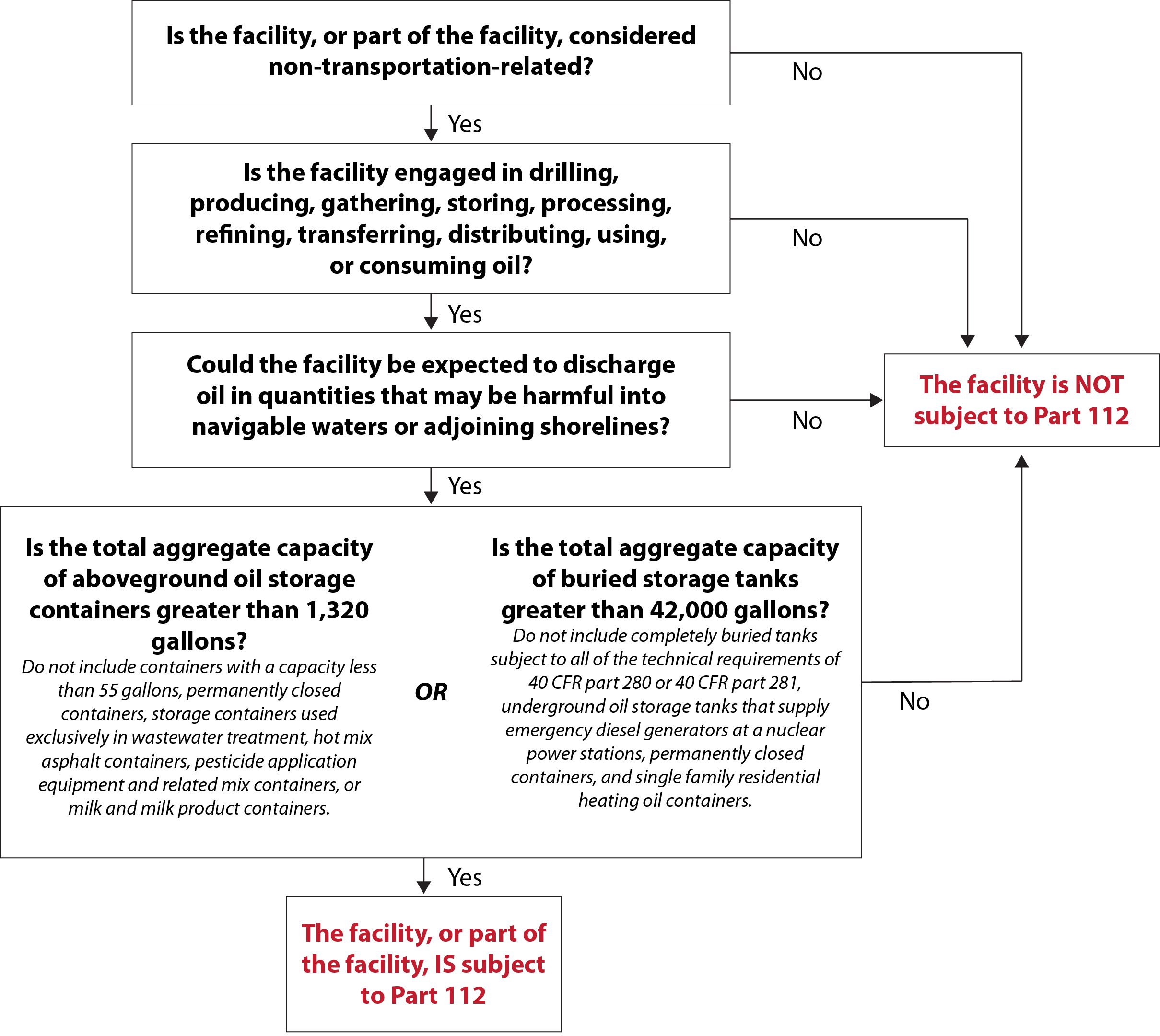
General applicability criteria
The Oil Pollution Prevention Standard at Part 112 applies to facility owners or operators if:
- The facility or part of the facility is considered non-transportation-related; and
- The facility is engaged in drilling, producing, gathering, storing, processing, refining, transferring, distributing, using, or consuming oil or oil products; and
- The facility could reasonably be expected to discharge oil in quantities that may be harmful, and the discharge is to U.S. navigable waters or adjoining shorelines; and
- The facility meets at least one of the following capacity thresholds:
- Aboveground oil storage capacity greater than 1,320 U.S. gallons, or
- Completely buried oil storage capacity greater than 42,000 U.S. gallons.
Below is a flowchart with all four criteria:
Facilities that are owned and operated by federal, state, or local government or tribal entities are equally subject to the regulation as any other facility (although the federal government is not subject to civil penalties).
Activities involving oil
- Some activities that are considered to be oil-related activities include: drilling, producing, gathering, storing, processing, refining, transferring, distributing, or consuming oil or oil products.
Paragraph (b) to Part 112.1 specifies the following oil-related activities are regulated: drilling, producing, gathering, storing, processing, refining, transferring, distributing, using, or consuming oil and oil products. That means these activities are subject to the Oil Pollution Prevention Standard provided the facility meets the other applicability criteria in section 112.1. The table provides examples of these activities.
| Oil-related activity | Examples |
|---|---|
| Drilling | Drilling a well to extract crude oil or natural gas and associated products (such as wet natural gas) from a subsurface field |
| Producing | Extracting product from a well and separating the crude oil and/or gas from other associated products (e.g., water, sediment) |
| Gathering | Collecting oil from numerous wells, tank batteries, or platforms and transporting it to a main storage facility, processing plant, or shipping point |
| Storing | Storing oil in containers prior to use, while being used, or prior to further distribution in commerce |
| Processing | Treating oil using a series of processes to prepare the oil for commercial use, consumption, further refining, manufacturing, or distribution |
| Refining |
|
| Transferring | Transferring oil between containers, such as between a railcar or tank truck and a bulk storage container, or between stock tanks and manufacturing equipment |
| Distributing | Selling or marketing oil for further commerce or moving oil using equipment such as highway vehicles, railroad cars, or pipeline systems in the confines of a non-transportation-related facility. Note that businesses commonly referred to as oil distributors and retailers are also “storing” oil, as described in this table |
| Using | Using oil for mechanical or operational purposes in a manner that does not significantly reduce the quantity of oil, such as using oil to lubricate moving parts, provide insulation, or for other purposes in electrical equipment, electrical transformers, and hydraulic equipment |
| Consuming | Consuming oil in a manner that reduces the amount of oil, such as burning as fuel in a generator |
Container types
- Facilities are subject to Part 112 if they have oil in aboveground containers; buried tanks; containers used for seasonal or temporary storage; or tanks that are partially buried or contained in a vault.
Under subparagraphs 112.1(b)(1) through (4), the Oil Pollution Prevention Standard is applicable to eligible facilities that have oil in:
- Aboveground containers;
- Completely buried tanks;
- Containers that are used for standby storage, for seasonal storage, or for temporary storage, or are not otherwise “permanently closed;” and
- “Bunkered tanks” or “partially buried tanks” or containers in a vault.
Containers include not only oil storage tanks, but also mobile or portable containers such as drums and totes, and oil-filled equipment such as electrical equipment (e.g., transformers and circuit breakers), manufacturing flow-through process equipment, and operational equipment.
Storage capacity thresholds
- Part 112 applies to facilities with oil capacity of more than 42,000 gallons stored underground, or more than 1,320 gallons stored aboveground.
Subparagraph 112.1(d)(2) of the Oil Pollution Prevention Standard limits the applicability to facilities with oil capacity above certain threshold amounts. Specifically, Part 112 applies to a facility that has more than 42,000 U.S. gallons of completely buried oil storage capacity or more than 1,320 U.S. gallons of aggregate aboveground oil storage capacity, provided the facility meets the other applicable criteria set forth in 112.1.
Once a facility is subject to the regulation, all aboveground containers and completely buried tanks are subject to the requirements (unless these containers are otherwise exempt from the regulation). For example, a facility could have 10,000 U.S. gallons of aggregate aboveground storage capacity in tanks and oil-filled equipment of 55 U.S. gallons or more, and a completely buried tank of 10,000 U.S. gallons that is not subject to all of the technical requirements of Part 280 or a state program approved under Part 281 (and therefore not exempt). Since the aboveground storage capacity exceeds 1,320 U.S. gallons, all of the tanks and oil-filled equipment, including the buried tank, are subject to the Spill Prevention, Control, and Countermeasure (SPCC) rule.
Subparagraphs 112.1(d)(2)(i) and (ii) clarify which containers are included and excluded when calculating total storage capacity at a facility in determining whether it exceeds the volume limits in the regulation.
Under the Oil Pollution Prevention Standard, if a container has the requisite capacity, it does not matter whether the container is actually filled to that capacity. The storage capacity of a container is defined as the shell capacity of the container.
Facility boundaries
- Part 112 helps to define what constitutes a facility for the purposes of SPCC and FRP requirements. An owner or operator may not characterize a facility for the purpose of avoiding SPCC and FRP requirements.
A facility may or may not be subject to the Spill Prevention, Control, and Countermeasure (SPCC) and Facility Response Plan (FRP) rule requirements depending on how the facility owner or operator aggregates buildings, structures or equipment and associated storage or type of activity. However, once the owner/operator determines the facility boundaries for SPCC applicability, then the same boundaries apply for determining applicability of the FRP rule requirements. An owner or operator may not characterize a facility so as to simply avoid applicability of the rule (for example, defining separate facilities around oil storage containers that are located side-by-side or within close proximity, and are used for the same purpose).
A lease may, at the owner or operator’s discretion, constitute a facility but does not necessarily create a facility. According to the definition of facility, contiguous or noncontiguous buildings, properties, leases, structures, installations, pipes, or pipelines under the ownership or operation of the same person may be considered separate facilities. A facility may also consist of parcels that are smaller or larger than an individual lease.
The following factors to determine the boundaries of a facility are not exclusive and simply serve as examples:
- Ownership, management, and operation of the buildings, structures, equipment, installations, pipes, or pipelines on the site;
- Similarity in functions, operational characteristics, and types of activities occurring at the site;
- Adjacency; or
- Shared drainage pathways (e.g., same receiving water bodies).
Farm-specific applicability
- The WRRDA of 2014 changes the way the SPCC rule is applied to farms.
- New rules, when adopted by the EPA, will likely bring more farms under the SPCC rule.
Under the Spill Prevention, Control, and Countermeasure (SPCC) rule (Part 112 Subparts A to C), a farm is “a facility on a tract of land devoted to the production of crops or raising of animals, including fish, which produced and sold, or normally would have produced and sold, $1,000 or more of agricultural products during a year.”
Section 1049 of the Water Resources Reform and Development Act (WRRDA) of 2014 impacts the SPCC rule for farms. Specifically, the law changes certain applicability provisions of the SPCC rule for farms and modifies the criteria under which a farmer may self-certify an SPCC Plan. Details may be found at the following:
- The Environmental Protection Agency’s (EPA’s) fact sheet called “Oil Spill Prevention, Control, and Countermeasures (SPCC Program): Farms and the Water Resources Reform and Development Act (WRRDA),” April 24, 2015.
- EPA’s publication called “Oil Storage on U.S. Farms: Risks and Opportunities for Protecting Surface Waters,” EPA-530-R-15-002, June 30, 2015.
The changes are not yet in the regulations at Part 112. EPA expects to promulgate a rule amending the SPCC requirements associated with the applicability thresholds and other WRRDA amendments. However, please note that EPA has said it intends to lower the greater-than-6,000-gallon threshold to greater than 2,500 gallons. Lowering the threshold will bring more farms under the SPCC rule.
Exemptions
- EPA lists several exemptions from Part 112, most related to facility or equipment location, size, capacity, and more.
The Environmental Protection Agency (EPA) exempts the following from Part 112:
- Any facility, equipment, or operation that is not subject to the jurisdiction of EPA under section 311(j)(1)(C) of the Clean Water Act (CWA), as follows:
- Any onshore or offshore facility, that due to its location, could not reasonably be expected to have a discharge as described in 112.1(b). This determination must be based solely upon consideration of the geographical and location aspects of the facility (such as proximity to navigable waters or adjoining shorelines, land contour, drainage, etc.) and must exclude consideration of man-made features such as dikes, equipment, or other structures, which may serve to restrain, hinder, contain, or otherwise prevent a discharge as described in 112.1(b).
- Any equipment, or operation of a vessel or transportation-related onshore or offshore facility subject to the authority and control of the Department of Transportation (DOT), as defined in the memorandum of understanding found at Appendix A to Part 112.
- Any equipment, or operation of a vessel or onshore or offshore facility which is subject to the authority and control of the DOT or the Department of the Interior, as defined in the memorandum of understanding found at Appendix B to Part 112.
- Any facility where the completely buried oil storage capacity is 42,000 U.S. gallons or less AND the aggregate aboveground oil storage capacity is 1,320 U.S. gallons or less.
- Completely buried oil tanks and associated piping and equipment that are subject to all of the technical requirements under Part 280 or 281.
- Underground oil storage tanks, including below-grade vaulted tanks that supply emergency diesel generators at a nuclear power generation facility licensed by the Nuclear Regulatory Commission (NRC) and subject to any NRC provision regarding design and quality criteria, including, but not limited to, 10 CFR 50.
- Permanently closed oil containers.
- Any container with an oil storage capacity less than 55 U.S. gallons.
- Any facility or part thereof used exclusively for wastewater treatment and not used to satisfy Part 112 (the production, recovery, or recycling of oil is not wastewater treatment for the purposes of this exemption).
- Motive power oil containers (the transfer of fuel or other oil into a motive power container at an otherwise regulated facility is not eligible for this exemption).
- Hot-mix asphalt or any hot-mix asphalt container.
- Containers storing heating oil used solely at a single-family residence.
- Pesticide application equipment or related mix containers (with adjuvant oil).
- Intra-facility oil gathering lines subject to the regulatory requirements of 49 CFR 192 or 195, except that such a line’s location must be identified and marked as ‘‘exempt’’ on the facility diagram as provided in subparagraph 112.7(a)(3), if the facility is otherwise subject to Part 112.
- Any milk and milk product container and associated piping and appurtenance.
- Any offshore oil drilling, production, or workover facility that is subject to the notices and regulations of the Minerals Management Service (MMS), as specified in the Memorandum of Understanding found in Appendix B to Part 112. Note that MMS was replaced in 2011 by the Bureau of Ocean Energy Management (BOEM) and the Bureau of Safety and Environmental Enforcement (BSEE).
Facilities are not required to include exempt oil containers or oil equipment when calculating the total oil storage capacity of the facility.
Terms related to exemptions under Part 112
- Several exemptions exist for Part 112.
The quickest way for a facility to avoid having to comply with the Part 112 exemptions are discussed here.
Permanently closed
- If they meet the proper definition, permanently closed containers are exempt from Part 112 and no longer count toward a facility’s total oil storage capacity.
Permanently closed containers are exempt from Part 112. Once permanently closed, a container no longer counts toward the total facility storage capacity, nor is it subject to the other requirements under Part 112. Part 112 does not require that permanently closed containers be removed from a facility.
In addition, any container brought on to a facility that has never stored oil is not subject to Part 112, nor is it counted toward the facility capacity until it stores oil. Any other container that at one time stored oil but no longer contains oil or sludge, which is brought onto a facility and meets the definition of permanently closed, is not subject to Part 112 nor is it counted toward the facility capacity until it stores oil.
Permanent closure requirements under Part 112 are separate and distinct from the closure requirements in hazardous waste regulations promulgated under Subtitle C of the Resource Conservation and Recovery Act (RCRA), such as Part 264.197 and 265.197.
Is it really permanently closed?
Part 112 does not include a provision to temporarily close containers to account for seasonal use of tanks or variable economic conditions and production rates at oil production facilities. In order for a container to be exempt from Part 112 requirements, the container must meet the following criteria for a permanently closed container:
- All liquid and sludge have been removed from each container and connecting line;
- All connecting lines and piping have been disconnected from the container and blanked off;
- All valves (except ventilation valves) have been closed and locked; and
- Conspicuous signs have been posted on each container stating that it is a permanently closed container and noting the date of closure.
A permanently closed container may remain at the facility. However, a facility owner or operator should review state and local requirements, which may require removal of a container when it is taken out of service. When a container is removed from the facility, the Spill Prevention, Control, and Countermeasure (SPCC) Plan must be amended and the technical amendment must be certified.
In the event that a permanently closed container is brought back into use (e.g., to accommodate variations in production rates), the SPCC Plan will need to be amended to reflect the capacity of the permanently closed container if this capacity was previously excluded from the facility total capacity.
Underground storage tank
- Underground storage tanks are exempt from Part 112 but are subject to other regulations (such as Parts 280 and 281) that require a facility to prevent, detect, and clean up oil spills from such tanks.
Under subparagraph 112.1(d)(4), the Oil Pollution Prevention Standard exempts completely buried storage tanks, as well as connected underground piping, underground ancillary equipment, and containment systems, when such tanks are subject to all of the technical requirements of Part 280 or a state program approved under Part 281 (also known as the Underground Storage Tank (UST) regulations). Although these tanks are exempt from the requirements of Part 112, they must still be marked on the facility diagram if the facility is otherwise subject to the Spill Prevention, Control, and Countermeasure (SPCC) rule (see subparagraph 112.7(a)(3)).
The regulations at Part 280 and Part 281 comprise the UST Program, which requires owners and operators of new tanks and tanks already in the ground to prevent, detect, and clean up releases. Part 112 only recognizes a subset of tanks covered by the UST Program regulations. Specifically, the UST Program defines a UST as a tank and any underground piping that has at least 10 percent of its combined volume underground. However, under Part 112, only completely buried tanks subject to all of the technical UST program requirements are exempt from Part 112. Any tanks that are not completely buried are considered aboveground storage tanks and subject to Part 112.
The following completely buried tanks are either excluded from the definition of UST or are exempt from the UST regulations at Part 280 (and therefore may be subject to Part 112 if they contain oil):
- Tanks with a capacity of 110 U.S. gallons or less;
- Farm or residential tanks with a capacity of 1,100 U.S. gallons or less used for storing motor fuel for non-commercial purposes;
- Tanks used for storing heating oil for consumptive use on the premises where stored;
- Tanks storing non-petroleum oils, such as animal fat or vegetable oil;
- Tanks on or above the floor of underground areas (e.g., basements or tunnels);
- Septic tanks and systems for collecting stormwater and wastewater; •
- Flow-through process tanks;
- Emergency spill and overfill tanks that are expeditiously emptied after use;
- Surface impoundments, pits, ponds, or lagoons;
- Any UST system holding Resource Conservation and Recovery Act (RCRA) hazardous waste;
- Any equipment or machinery that contains regulated substances for operational purposes such as hydraulic lift tanks and electrical equipment tanks;
- Liquid trap or associated gathering lines directly related to oil or gas production or gathering operations;
- Pipeline facilities regulated under the Natural Gas Pipeline Safety Act of 1968, the Hazardous Liquid Pipeline Safety Act of 1979, or intrastate pipelines regulated under state laws comparable to the provisions of above laws; and
- Any UST system that contains de minimis concentration of regulated substances.
The following are examples of deferrals from the UST regulations (and therefore may be subject to Part 112):
- Wastewater treatment tank systems;
- Any UST systems containing radioactive materials that are regulated under the Atomic Energy Act of 1954;
- Airport hydrant fuel distribution systems; and
- UST systems with field-constructed tanks.
Note that, at an otherwise Part-112-regulated facility, any transfer to or from completely buried storage tanks is regulated because it is a potential source of discharge of oil into navigable waters or adjoining shorelines. Because a loading/unloading rack, or other transfer area, associated with a UST is not typically part of the UST system, it is not subject to all of the technical requirements of Part 280 or Part 281. Therefore, such a loading/unloading rack is regulated under the Part 112 regulations in the same manner as any other transfer equipment or transfer activity located at an otherwise Part-112-regulated facility.
Additional and/or more stringent requirements may exist in a state-approved program under Part 281, and they may also impact Part 112 applicability. For example, a state may choose to regulate a UST used for storing heating oil for consumptive use on the premises where stored. Thus, under the state program the UST is subject to all the technical requirements of a Part 281 program and therefore exempt from Part 112.
Wastewater treatment facilities
- The wastewater treatment exemption excludes from Part 112 those facilities or parts of facilities that are used exclusively for wastewater treatment.
The wastewater treatment exemption, outlined at Part 112.1(d)(6), excludes from the Part 112 requirements those facilities or parts of facilities that are used exclusively for wastewater treatment, and are not used to meet Part 112 requirements. Do not count the capacity of these exempt containers when calculating facility aggregate capacity.
Many of the wastewater treatment facilities or parts thereof are subject to the National Pollutant Discharge Elimination System (NPDES) or state-equivalent permitting requirements that involve operating and maintaining the facility to prevent discharges. The NPDES or state-equivalent process ensures review and approval of the facility’s plans and specifications; operation/maintenance manuals and procedures; and stormwater pollution prevention plans (SWPPPs), which may include best management practice (BMP) plans.
For the purposes of the exemption, the production, recovery, or recycling of oil is not considered wastewater treatment. These activities generally lack NPDES or state-equivalent permits and thus lack the protections that such permits provide. The goal of an oil production, oil recovery, or oil recycling facility is to maximize the production or recovery of oil, while eliminating impurities in the oil, including water, whereas the goal of a wastewater treatment facility is to purify water. Additionally, produced water is not considered wastewater and is therefore not eligible for this exemption. However, produced water containers used exclusively for wastewater treatment at dry gas production facilities are eligible for the wastewater treatment exemption.
The exemption also does not apply to a wastewater treatment facility (or part of that facility) that is used to store oil. In those instances, the oil storage capacity must be counted as part of the total facility storage capacity. For example, if there is a 1,000-gallon storage container that contains oil removed from an exempt oil/water separator and a 500-gallon storage container for an emergency generator, the total aboveground storage capacity for the facility would be 1,500 U.S. gallons, and the facility may potentially be regulated by Part 112.
A wastewater treatment facility (or parts of that facility) used to meet a Part 112 requirement, including an oil/water separator used to meet any spill prevention, control, and countermeasure (SPCC) requirement, is not exempt. Oil/water separators used to meet SPCC requirements include those used to satisfy the secondary containment requirements of subparagraphs 112.7(c), 112.7(h)(1), and/or 112.8(c)(2) or 112.8(c)(11). Although not exempt, oil/water separators used to satisfy secondary containment requirements of Part 112 do not count toward storage capacity.
Motive power
- A motive power container is defined as any onboard bulk storage container used primarily to power the movement of a motor vehicle, or ancillary onboard oil-filled operational equipment.
Motive power container means any onboard bulk storage container used primarily to power the movement of a motor vehicle, or ancillary onboard oil-filled operational equipment (Part 112.2). An onboard bulk storage container which is used to store or transfer oil for further distribution is not a motive power container. The definition of motive power container does not include oil drilling or workover equipment, including rigs.
Motive power containers on vehicles used solely at non-transportation-related facilities fall under the Environmental Protection Agency (EPA) jurisdiction but are exempt from Part 112. Section 112.1(d)(2)(ii) excludes the capacity of these containers from facility capacity calculations.
Bulk storage container used for propulsion
Containers on motor vehicles that provide the vehicle with a means of propulsion are considered motive power containers. Examples of motor vehicles which have containers used to individually provide their own means of propulsion from location to location within a facility or between facilities include:
- Aircraft,
- Cherry pickers,
- Self-propelled cranes,
- Self-propelled aviation ground service equipment vehicles,
- Self-propelled heavy vehicles (e.g., used in forestry, agricultural, mining, excavation and construction applications), and
- Locomotives.
Ancillary on-board equipment
Ancillary on-board equipment includes hydraulic and lubrication operational oil-filled containers used for other ancillary functions of a motor vehicle. It also includes motor vehicle bulk storage containers that serve a non-operational purpose in addition to the propulsion of the motor vehicle; for example, a bulk storage container that supplies fuel to an engine that provides the propulsion for that motor vehicle, as well as its auxiliary units and functions (e.g., heaters, air conditioning units, and electrical power generation, etc.).
Exclusions from the motive power container definition
The exemption does not include non-self-propelled stationary or towed equipment, such as towed ground service equipment or any type of oil-powered generator (gensets). The following are examples of equipment that are not motive power containers because they do not include containers used for propulsion: •
- Towed aviation ground service equipment,
- Non-self-propelled construction/cargo cranes,
- Non-self-propelled (forestry, agricultural, mining, excavation or construction) equipment,
- Oil-powered generators,
- Fire pumps, and
- Compressors.
An onboard bulk storage container used to store or transfer oil for further distribution is also not a motive power container. An onboard bulk storage container that supplies oil for the movement of a vehicle or operation of onboard equipment, and at the same time is used for the distribution or storage of this oil is not eligible for the exemption. This situation includes, for example, a mobile refueler that has an onboard bulk storage container used to distribute fuel to other vehicles on a site and which also draws its engine fuel (for propulsion) from that bulk container.
Oil drilling and workover equipment (including rigs) are not eligible for the motive power container exemption because they are specifically excluded from the definition of a motive power container. Although drilling and workover rigs are not exempt, other types of motive power containers located at drilling or workover facilities (e.g., trucks, automobiles, bulldozers, seismic exploration vehicles, or other earth-moving equipment) are exempt.
Oil transfers to motive power containers
Regardless of the exemption for motive power containers, oil transfer activities occurring within a Part-112-regulated facility are regulated. An example of such an activity would be the transfer of oil from an oil storage container via a dispenser to a motive power container. This transfer activity is subject to the general secondary containment requirements of 112.7(c).
Intra-facility gathering lines
- Intra-facility gathering lines may fall under the jurisdiction of the EPA and DOT.
Intra-facility gathering lines (i.e., gathering lines found within the confines of a non-transportation-related facility) may be under the jurisdiction of both the Environmental Protection Agency (EPA) and the Department of Transportation (DOT). However, certain DOT requirements for pipelines are considered to be similar in scope to Part 112 regulations. Therefore, intra-facility gathering lines that are subject to DOT regulatory requirements at Part 192 (Transportation of Natural and Other Gas by Pipeline) or Part 195 (Transportation of Hazardous Liquids by Pipeline) are exempt from Part 112 under 112.1(d)(11).
If intra-facility gathering lines are not subject to DOT regulatory requirements (i.e., gathering lines that by statute are subject to DOT jurisdiction, yet are not subject to the DOT regulations), they remain subject to Part 112. Other equipment and piping at an oil production facility (such as flowlines) remain subject to Part 112 requirements. EPA considers intra-facility gathering lines to be subject to EPA’s jurisdiction if they are located within the boundaries of an otherwise regulated Part-112-covered facility.
The exemption requires owners or operators of a facility to identify and mark as “exempt” the location of exempt piping on the facility diagram. This requirement will assist both facility and EPA personnel in defining the boundaries of EPA and DOT jurisdiction and provide response personnel with information used to identify hazards during a spill response activity. More information about facility diagram requirements is provided at Written plans.
Milk and milk product containers
- Milk and milk product containers are exempt from Part 112. Butter, cheese, and dry milk containers are a few examples.
Milk and milk product containers and associated piping and appurtenances are exempt from the Part 112 under subparagraph 112.1(d)(12) and excluded from facility capacity calculations in subparagraph 112.1(d)(2)(ii). Butter, cheese, and dry milk containers are a few examples of milk product containers subject to the exemption.
All milk and/or milk product transfer and processing activities are included in the scope of this exemption from Part 112. For more information on exempted milk and milk product containers, see the final rule in the Federal Register dated April 18, 2011.
What is oil?
- EPA section 112.2 defines what substances are considered oils, based in part on the description included in the Clean Water Act.
- Any substance which is designated as a hazardous substance under CERCLA is not an oil.
To understand the oil-related regulations and their applicability, facilities must first understand the term “oil.”
The Environmental Protection Agency (EPA) Part 112.2 defines oil as “oil of any kind or in any form, including, but not limited to: fats, oils, or greases of animal, fish, or marine mammal origin; vegetable oils, including oils from seeds, nuts, fruits, or kernels; and, other oils and greases, including petroleum, fuel oil, sludge, synthetic oils, mineral oils, oil refuse, or oil mixed with wastes other than dredged spoil.”
Part 112 applies to the owners and operators of facilities with the potential to discharge oil in quantities that may be harmful to navigable waters or adjoining shorelines. The Part 112 definition of oil derives from section 311(a)(1) of the Clean Water Act (CWA).
Oil Pollution Act (OPA) section 1001 defined oil separately to exclude any substance which is specifically listed or designated as a hazardous substance under the Comprehensive Environmental Response, Compensation, and Liability Act (CERCLA) and which is subject to provisions of that Act. Although oil is defined separately under OPA, that definition did not amend the original CWA definition of oil in section 311(a)(1) and, therefore, was not incorporated into the definition of oil under section 112.2 that applies to both spill prevention, control, and countermeasure (SPCC) and facility response plan (FRP) regulatory requirements. In response to Edible Oil Regulatory Reform Act (EORRA) of 1995 (33 U.S.C. 2720) requirements, the oil definition under section 112.2 was revised to include the categories of oil in EORRA. Those categories are: (1) petroleum oils, (2) animal fats and vegetable oils; and (3) other non-petroleum oils and greases.
The U.S. Coast Guard (USCG) maintains a separate list of substances it considers oil for its regulatory purposes. The list is available on the USCG website and may be used as a guide when determining if a particular substance is an oil. However, for purposes of EPA’s regulations, the USCG list is not comprehensive and does not include all oils that are subject to Part 112.
Petroleum and non-petroleum oil
- Petroleum oil is petroleum in any form. Non-petroleum oil includes, but is not limited to, fats, oils and greases derived from animal, fish, or vegetable sources.
Petroleum oil means petroleum in any form, including but not limited to crude oil, fuel oil, mineral oil, sludge, oil refuse, and refined products.
Non-petroleum oil means oil of any kind that is not petroleum-based, including but not limited to: fats, oils, and greases of animal, fish, or marine mammal origin; and vegetable oils, including oils from seeds, nuts, fruits, and kernels.
Part 112 applies to both petroleum oils and non-petroleum oils. Petroleum oils include, but are not limited to, crude and refined petroleum products, asphalt, gasoline, fuel oils, mineral oils, naphtha, sludge, oil refuse, and oil mixed with wastes other than dredged spoil. Non-petroleum oils and greases include coal tar, creosote, silicon fluids, pine oil, turpentine, and tall oils.
Subpart B of Part 112 covers both “petroleum oils and non-petroleum oils.” Petroleum oils and non-petroleum oils, including synthetic oils, share common physical properties and produce similar environmental effects. Petroleum and non-petroleum oils can enter all parts of an aquatic system and adjacent shoreline, and similar methods of containment, removal, and cleanup are used to reduce the harm created by spills of both types of oils.
Synthetic oil
- Synthetic oils are created by chemical synthesis rather than by refining petroleum or extracting from animal or plant materials.
Synthetic oils are used in a wide range of applications, including as heat transfer fluids, engine fluids, hydraulic and transmission fluids, metalworking fluids, dielectric fluids, compressor lubricants, and turbine lubricants. Synthetic oils are created by chemical synthesis rather than by refining petroleum crude or extracting oil from plant seeds. Oils that are derived from plant material may be considered animal fats and vegetable oils under Subpart C of Part 112.
Animal fats and vegetable oils (AFVOs)
- Animal fat means a non-petroleum oil, fat, or grease of animal, fish, or marine mammal origin. Vegetable oil means a non-petroleum oil or fat of vegetable origin.
Animal fats and vegetable oils are covered under Part 112.
Animal fat means a non-petroleum oil, fat, or grease of animal, fish, or marine mammal origin. Animal fats include, but are not limited to, fats, oils, and greases of animal origin (for example, lard and tallow), fish (for example, cod liver oil), or marine mammal origin (for example, whale oil).
Vegetable oil means a non-petroleum oil or fat of vegetable origin, including but not limited to oils and fats derived from plant seeds, nuts, fruits, and kernels. Examples of vegetable oils include corn oil, rapeseed oil, coconut oil, palm oil, soybean oil, sunflower seed oil, cottonseed oil, and peanut oil.
Produced water
- Produced water is the oil and water mixture that results from the separation of crude oil or gas from the fluids or gases extracted from the oil/gas reservoir.
- Because it can cause harm if discharged, produced water is regulated as oil under Part 112.
Part 112 applies to produced water from an oil well. Produced water is the oil and water mixture resulting from the separation of crude oil or gas from the fluids or gases extracted from the oil/gas reservoir, prior to disposal, subsequent use (e.g., re-injection or beneficial reuse), or further treatment. Produced water’s chemical and physical characteristics vary considerably depending on the geologic formation, usually being commingled with oil and gas at the wellhead, and changing in composition as the oil or natural gas fraction is separated and sent to market.
Produced water is typically collected in produced water containers at the end of the oil and gas treatment process, and often accumulates emulsified oil not captured in the separation process. Under normal operating conditions, a layer of oil may be present on top of the fluids. The amount of oil by volume observed in produced water storage containers varies, but based on the Environmental Protection Agency (EPA)’s assessment, is generally estimated to range from less than one to 10 percent by volume and can be greater. Oil may be present not only in free phase, but also in other forms, such as in a dissolved phase, emulsion or a sludge at the bottom of the produced water container.
Oil discharges to navigable waters or adjoining shorelines from an oil/water mixture in a produced water container may cause harm. Such mixtures in the produced water container are regulated as oil under Part 112. Therefore, the capacity of produced water containers counts toward the facility aggregate oil storage capacity. Produced water containers at oil production, oil recycling, or oil recovery facilities are not eligible for the wastewater treatment exemption in subparagraph 112.1(d)(6).
Other substances
- Certain other substances may be regulated as oil, including but not limited to some forms of asphalt, natural gas condensate, oil and water mixtures, denatured ethanol, and biodiesel fuel.
Other substances may pose a challenge to facilities attempting to determine if they have an oil onsite.
Asphalt
Asphalt is a thermoplastic material, composed of unsaturated aliphatic and aromatic compounds, that softens when heated and hardens upon cooling. Within a certain temperature range, it exhibits viscoelastic properties with viscous flow behavior and elastic deformation. All types of asphalt are petroleum oil products, and its composition depends on the source of the crude oil and the process used to manufacture it.
The Environmental Protection Agency (EPA) regulation Part 112 applies to asphalt cement (AC), as well as to asphalt derivatives such as cutbacks and emulsions. Because of the operational conditions under which AC, cutbacks and emulsions are used and stored, they do pose a risk of being discharged into navigable waters or adjoining shorelines. Although AC is semi-solid or solid at ambient temperature and pressure, it is generally stored at elevated temperatures. Hot AC is liquid — similar to other semi-solid oils, such as paraffin wax and heavy bunker fuels — and therefore is capable of flowing. Cutbacks and emulsions are liquid at ambient temperature, and, because of their low viscosity, they may flow when discharged onto the ground. All of these oils are regulated under Part 112 to prevent discharges to navigable waters or adjoining shorelines.
However, hot-mix asphalt (HMA) and HMA containers are exempt from Part 112. HMA is a blend of AC and aggregate material, such as stone, ground tires, sand, or gravel, which is formed into final paving products for use on roads and parking lots. HMA is unlikely to flow as a result of the entrained aggregate, such that there would be very few circumstances, if any, in which a discharge of HMA would have the potential to reach navigable waters or adjoining shorelines.
Natural gas and condensate
Part 112 does not apply to natural gas (including liquid natural gas and liquid petroleum gas). EPA does not consider highly volatile liquids that volatilize on contact with air or water, such as liquid natural gas or liquid petroleum gas, to be oil. Furthermore, the agency has stated that hydrocarbons in a gaseous phase under ambient pressure and temperature, such as natural gas, present at Part 112-regulated facilities are exempt.
However, natural gas liquid condensate (often referred to as “natural gasoline” or “drip gas”) is an oil subject to Part 112. Condensate can accumulate in tanks, containers, or other equipment. For the purposes of determining applicability, containers with 55 gallons or more in capacity storing condensate must be included in a natural gas facility’s total oil storage capacity calculation.
Oil and water mixtures
Oil and water mixture containers are subject to Part 112. A mixture of wastewater and oil is “oil” under the statutory and regulatory definition of the term (33 U.S.C. 1321(a)(1) and Part 110.2 and 112.2). A discharge of “wastewater containing oil” to navigable waters or adjoining shorelines in a ‘‘harmful quantity’’ (as defined at Part 110) is prohibited. One example of an oil and water mixture is produced water.
Hazardous substances and hazardous waste
The definition of “oil” in section 112.2 includes, but is not limited to, “oil mixed with wastes other than dredged spoil.” Oils covered under Part 112 include certain hazardous substances or hazardous wastes that are oils, as well as certain hazardous substances or hazardous wastes that are mixed with oils. Containers storing these substances may also be covered by other regulations, such as those prompted by the Resource Conservation and Recovery Act (RCRA) or Comprehensive Environmental Response, Compensation, and Liability Act (CERCLA, also known as Superfund). For example, the definition of oil under section 112.2 includes “used oil” because it is an oil mixed with wastes. “Used oil,” as defined in EPA’s Standards for the Management of Used Oil at Part 279.1, means any oil that has been refined from crude oil, or any synthetic oil, that has been used and as a result of such use is contaminated by physical or chemical impurities.
EPA inspectors may evaluate whether containers storing hazardous substances or mixtures of wastes contain oil. Hazardous substances or hazardous wastes that are neither oils nor mixed with oils are not subject to Part 112 requirements. For purposes of Part 112, the Clean Water Act (CWA) section 311(b)(2) hazardous substances as identified under Part 116 are not considered oils. However, an oil mixture that includes a CWA hazardous substance is subject to Part 112 when it meets the definition of oil in the regulation. For example, benzene is a CWA hazardous substance and therefore does not meet the definition of oil in section 112.2; however, benzene is a constituent of gasoline which is a mixture that includes other oils. Gasoline is an oil as defined under Part 112.2.
Although the rule contains an exemption for completely buried tanks that are subject to all underground storage tank (UST) technical requirements of Part 280 and/or a state program approved under Part 281 under subparagraph 112.1(d)(2)(i) or (d)(4), tanks containing RCRA hazardous wastes are not subject to the UST rules. Therefore, when RCRA hazardous waste tanks located at a facility subject to Part 112 also contain oil, they too are subject to the Part 112 requirements.
Denatured ethanol used in renewable fuels
Renewable fuels, such as E85 or “flex fuel” (15 percent unleaded gasoline and 85 percent ethanol), are produced in a blending process. Ethanol used for fuel often contains a denaturing additive (typically gasoline, natural gasoline, diesel fuel, or other oil petroleum product) which is oil. Therefore, the final denatured ethanol is also considered an oil, and facilities handling or storing denatured ethanol may be subject to the Part 112 requirements. An EPA letter dated November 7, 2006, details the agency’s position on denatured ethanol.
Biodiesel and biodiesel blends
Biodiesel and biodiesel blends are other types of renewable fuels that are often stored and handled at facilities regulated under Part 112. Biodiesel, designated B100, is a domestic, renewable fuel for diesel engines derived from natural oils like soybean oil. Biodiesel is comprised of mono-alkyl esters of long chain fatty acids derived from vegetable oils or animal fats.
Biodiesel can be used in any concentration with petroleum-based diesel fuel in existing diesel engines with little or no modification. Biodiesel is not the same as raw vegetable oil. It is produced by a chemical process which removes the glycerin from the oil. Biodiesel is typically produced by a reaction of a vegetable oil or animal fat with an alcohol such as methanol or ethanol in the presence of a catalyst to yield mono-alkyl esters and glycerin, which is removed.
Biodiesel blends are a blend of biodiesel fuel with petroleum-based diesel fuel, designated BXX, where XX represents the volume percentage of biodiesel fuel in the blend. Both biodiesel (B100) and biodiesel blends are considered oil for the purposes of Part 112.
What is a facility?
- Facility means any mobile or fixed onshore or offshore building, property, parcel, lease, structure, installation, equipment, pipe, or pipeline (other than a vessel or a public vessel) used in oil well drilling operations, oil production, oil refining, oil storage, oil gathering, oil processing, oil transfer, oil distribution, and oil waste treatment, or in which oil is used.
- While a facility owner/operator has some discretion in defining the parameters of the facility, the boundaries of a facility may not be drawn to solely avoid regulation under Part 112.
It is important to know the meaning of the term facility and its various types in order to determine the applicability of Part 112 as a whole and to determine which sections come into play.
Facility means any mobile or fixed onshore or offshore building, property, parcel, lease, structure, installation, equipment, pipe, or pipeline (other than a vessel or a public vessel) used in oil well drilling operations, oil production, oil refining, oil storage, oil gathering, oil processing, oil transfer, oil distribution, and oil waste treatment, or in which oil is used, as described in Appendix A to Part 112.
The boundaries of a facility depend on several site-specific factors, including but not limited to the ownership or operation of buildings, structures, and equipment on the same site and types of activity at the site. Contiguous or non-contiguous buildings, properties, parcels, leases, structures, installations, pipes, or pipelines under the ownership or operation of the same person may be considered separate facilities.
The definition of facility governs the overall applicability of Part 112, and thus is used to determine the scope of a facility’s boundaries in order to determine if the facility is subject to the spill prevention, control, and countermeasure (SPCC) and/or facility response plan (FRP) requirements. The boundary or extent of a “facility” depends on site-specific circumstances. Factors that may be considered relevant in delineating the boundaries of a facility under Part 112 may include, but are not limited to:
- Ownership, management, and operation of the buildings, structures, equipment, installations, pipes, or pipelines on the site;
- Similarity in functions, operational characteristics, and types of activities occurring at the site;
- Adjacency; or
- Shared drainage pathways (e.g., same receiving water bodies).
The facility owner or operator, or a professional engineer (PE) on behalf of the facility owner/operator, must make a judgment of what constitutes the “facility.” Once the owner or operator determines the facility boundaries for purposes of the SPCC rule (Part 112 Subparts A to C), then the same boundaries apply for FRP applicability under sections 112.20 and 112.21. Note that generally, an SPCC-regulated facility excludes components that are not subject to the Environmental Protection Agency’s (EPA’s) jurisdiction but are instead subject solely to the jurisdiction of other agencies, such as the Department of Transportation (DOT) or the U.S. Coast Guard (USCG).
Contiguous or non-contiguous buildings, properties, parcels, leases, structures, installations, pipes, or pipelines under the ownership or operation of the same person may be considered separate facilities for SPCC purposes. For example, a single facility may be composed of various oil-containing areas spread over a relatively large campus, such as multiple operational areas within a military base. Each operational area may be considered a separate facility. The military base may not necessarily include single-family homes occupied by military personnel as part of the facility if these are considered personal space similar to civilian single-family residences. However, larger military barracks for which a branch of the military controls, operates, and maintains the space would be included as part of a facility.
While the facility owner/operator has some discretion in defining the parameters of the facility, the boundaries of a facility may not be drawn to solely avoid regulation under Part 112. For example, two contiguous operational areas, each with 700 gallons in aboveground storage capacity, that have the same owner, perform similar functions, are attended by the same personnel, and are in other ways indistinguishable from each other, would reasonably be expected to represent a single facility under the SPCC rule, and would therefore be required to have an SPCC Plan, since the capacity of this facility is above the 1,320-gallon aboveground threshold. These two operational areas would not be defined as two separate facilities under the definition of “facility” in section 112.2. EPA reserves the right to make its own facility boundary determination after reviewing the plan or inspecting the facility.
The facility owner or operator is responsible for ensuring that an SPCC Plan is prepared. A single site may have multiple owners and/or operators, and therefore may be divided into multiple facilities. Factors to consider in determining which owner or operator should prepare the plan include who has control over day-to-day operations of the facility or particular containers and equipment, who trains the employee(s) involved in oil handling activities, who will conduct the required inspections and tests, and who will be responsible for responding to and cleaning up any discharge of oil. EPA expects that the owners and operators will cooperate to prepare one or more plans, as appropriate, to be kept at each facility when attended more than four hours per day.
SPCC facilities include not only permanent facilities with fixed storage and equipment, but also those that have only standby, temporary, and seasonal storage as described under subparagraph 112.1(b)(3), as well as construction facilities. The owners and operators of mobile facilities (addressed in paragraph 112.3(a)) can create a general SPCC Plan, instead of developing a new plan each time the facility is moved to a new location. When a mobile facility is moved, it must be located and installed using the spill prevention practices outlined in its plan. In accordance with subparagraph 112.3(a)(2), the plan is only required to be implemented “while the facility is in a fixed (non-transportation) operating mode.” Types of operations (mobile facilities) using a mobile plan include, but are not limited to, mobile fueling operations, road construction projects, drilling operations, and workover operations.
Onshore facility and offshore facility
- For the purposes of the EPA, an onshore facility is any facility of any kind located in, on, or under any land within the United States, other than submerged lands.
- An offshore facility is any facility of any kind (other than a vessel or public vessel) located in, on, or under any of the navigable waters of the United States, and any facility of any kind that is subject to the jurisdiction of the United States and is located in, on, or under any other waters.
The Environmental Protection Agency (EPA) has the authority to regulate non-transportation-related onshore and offshore facilities that could reasonably be expected to discharge oil into navigable waters of the U.S. or adjoining shorelines. Section 112.2 defines an “onshore facility” as “any facility of any kind located in, on, or under any land within the United States, other than submerged lands.” Requirements under Subparts B and C are divided based on the location of the facility and the type of operations. Sections 112.8 and 112.12 apply to all onshore facilities (excluding oil production facilities). Section 112.9 applies to all onshore oil production facilities, and section 112.10 applies to all onshore oil drilling and workover facilities. Finally, sections 112.20 and 112.21 apply to any non-transportation-related onshore facilities that, because of their location, could reasonably be expected to cause substantial harm to the environment by discharging oil into or on the navigable waters or adjoining shorelines.
“Offshore facility” means any facility of any kind (other than a vessel or public vessel) located in, on, or under any of the navigable waters of the United States, and any facility of any kind that is subject to the jurisdiction of the United States and is located in, on, or under any other waters. Section 112.11 applies to all offshore oil drilling, production, or workover facilities.
Some facilities may include both onshore and offshore components. In these instances, facilities may be considered “hybrid” facilities and subject to more than one set of requirements under Part 112. For example, an oil production facility located along a coastline that has a tank battery located onshore and associated wellheads and flowlines located offshore may be subject to the requirements of section 112.9 (for onshore oil production facilities) and section 112.11 (for offshore oil drilling, workover and production facilities).
Production facility
- A production facility includes all the structures, piping, and equipment used in the production, extraction, recovery, lifting, stabilization, separation or treatment of oil.
A production facility is a type of facility as defined in Part 112.2. A production facility includes all the structures (including but not limited to wells, platforms, or storage facilities), piping (including but not limited to flowlines or intra-facility gathering lines), or equipment (including but not limited to workover equipment, separation equipment, or auxiliary non-transportation-related equipment) used in the production, extraction, recovery, lifting, stabilization, separation or treatment of oil (including condensate) and associated storage or measurement and is located in an oil or gas field, at a facility.
The definition of “production facility” in section 112.2 is narrower than the definition of facility and is used to determine which sections of the rule may apply at a particular facility. This definition governs whether such structures, piping, or equipment are subject to section 112.9. That is, if a facility meets the definition of a production facility, the owner or operator must comply with section 112.9 or section 112.11 (depending on the characteristics of the facility). Additionally, the sections for administrative and general requirements under Part 112 apply as well (except for the security requirements under paragraph 112.7(g)).
The definition of “production facility” is consistent with the definition of “facility” in emphasizing flexibility in how a facility owner or operator can determine facility boundaries.
A production facility for purposes of Part 112 is one that is involved with producing or extracting petroleum crude oil from a reservoir and not any other type of oil production, such as animal fat and vegetable oil (AFVO) production. In fact,
- The definition of production facility addresses petroleum crude oil production, extraction, recovery, lifting, stabilization, separation or treatment and associated storage or measurement.
- The definition also includes terms associated with petroleum crude oil production, such as gathering lines and flowlines which are exclusively associated with upstream petroleum crude oil/gas production, not AFVO production or processing facilities. The term “oil or gas field” is used exclusively in upstream crude oil and gas production, not in AFVO production.
Drilling and workover facility
- Drilling and workover activities are part of oil production facility operations, and regulated as such; however, different provisions of the SPCC rule apply to these different activities.
Under the spill prevention, control, and countermeasure (SPCC) rule (Part 112 Subparts A to C), the term “production facility” can encompass drilling and workover activities, as well as oil production operations. However, different specific provisions of the rule apply to these different activities.
Drilling activities typically involve the initial establishment of an oil well: drilling the borehole, inserting, running, and cementing the casing, and completing the well to start the flow of well fluids to the surface.
Workover operations involve maintenance or remedial work that may be necessary to improve productivity during the life of the well. Workover operations may also include activities associated with the initial well completion process.
Both drilling and workover activities tend to be temporary in nature and are performed using mobile rigs and associated equipment. Thus a drilling and/or workover facility is considered a mobile facility. Mobile facilities may use a general SPCC Plan so that a new plan need not be prepared each time the mobile facility is moved to a new site. For example, it is not necessary to amend the plan for a drilling rig every time the operator moves the rig to drill a well in a field containing multiple wells. The same approach for mobile facilities applies to workover operations and activities.
For drilling and workover operations, the owner or operator is required to develop an SPCC Plan under paragraph 112.3(c) because a drilling or workover facility is considered a mobile facility. The administrative and general requirements of the SPCC rule (sections 112.1 through 112.7), as well as the specific requirements in section 112.10 (for onshore facilities) or section 112.11 (for offshore facilities) apply to the facility.
Once the well is completed and the well fluids are flowing, the completion (workover) and/or drilling rig is removed from the site and production equipment, such as a pump or valve assembly, is set up to extract or control the flow of oil from the well. At this point, drilling and or workover activities have ceased and production has begun; the facility is considered an oil production facility. The processes performed at a typical oil production facility include extraction, separation and treatment, storage, and transfer. The owner or operator of an oil production facility is subject to the administrative and general requirements of the SPCC rule (sections 112.1 through 112.7) as well as the specific requirements in section 112.9 (for onshore facilities) or section 112.11 (for offshore facilities). Typically, a gas plant is not considered an oil production facility.
During the life of an oil well, maintenance or remedial work may be necessary to improve productivity. A specialized workover rig, equipment, and associated containers are brought onsite to perform maintenance or remedial activities. Workover activities are a distinct operation and may be conducted by a separate owner or operator; therefore, a workover operation may be considered a separate mobile facility and be described in a different SPCC Plan, separate from the oil production facility. Although production activities may temporarily cease during workover, if the production equipment and containers (such as those found in a tank battery) remain operable, then the oil production facility owner/operator must maintain his or her own SPCC Plan during workover activities.
Farm
- Though the definition of farm is narrower than the definition of facility, if a farm meets the criteria, it may be subject to SPCC and/or FRP requirements.
The Environmental Protection Agency (EPA) defines “farm” in Part 112 by adapting the definition used by the National Agricultural Statistics Service (NASS) in its Census of Agriculture. NASS defines a farm as any place from which $1,000 or more of agricultural products were produced and sold, or normally would have been sold, during the census year. Operations receiving $1,000 or more in federal government payments are counted as farms, even if they have no sales and otherwise lack the potential to have $1,000 or more in sales.
EPA also considered the “farm tank” definition under the underground storage tank (UST) regulations at Part 280. As defined in section 280.12, a farm tank is a tank located on a tract of land devoted to the production of crops or raising of animals, including fish.
The term “farm” includes fish hatcheries, rangeland, and nurseries with growing operations, but does not include laboratories where animals are raised, land used to grow timber, and pesticide aviation operations. This term also does not include retail stores or garden centers where the product of nursery farms is marketed, but not produced, nor does the agency interpret the term “farm” to include golf courses or other places dedicated primarily to recreational, aesthetic, or other nonagricultural activities. Additionally, the definition of farm does not include agribusinesses because these businesses (e.g., oil marketing and distribution to farmers) are distinctly different from farms.
The definition of “farm” is narrower than the definition of “facility.” The definition of “facility” governs the overall applicability of Part 112, and thus is used to determine whether the owner or operator (e.g., a farmer) is subject to the spill prevention, control, and countermeasure (SPCC) and/or facility response plan (FRP) requirements and to determine the scope of his or her facility.
Natural gas production/treatment facilities and pipelines
- Because natural gas condensate is considered an oil, facilities that produce or store it may be regulated under Part 112 if the other criteria are met.
- Five scenarios are outlined in which facilities that produce or treat natural gas may be subject to SPCC rules.
The Environmental Protection Agency (EPA) does not regulate natural gas under Part 112. However, natural gas condensate is considered an oil and is regulated. For the purposes of determining Part 112 applicability, containers with 55 gallons or more in capacity storing condensate must be included in a natural gas facility’s total oil storage capacity calculation. Ancillary oil storage in other areas of the facility, such as fuel or lubrication oil, and oil-filled equipment, is also counted. Natural gas production or treatment facilities and pipeline systems commonly have associated oil storage, including oil-containing equipment such as compressors, drip tanks, and separators that may store motor oil, lubricants, crude oil impurities removed from the gas stream, and liquid condensate. Equipment that compresses or pumps the natural gas is not regulated unless there is oil-filled operational equipment associated with it that meets the applicability requirements of the rule.
The definition of “production facility” in section 112.2 specifies that an oil production facility involves the “production, extraction, recovery, lifting, stabilization, separation or treating of oil.” Therefore, under Part 112, any natural gas treatment facility that does not produce oil or condensate is not regulated as a production facility but may be regulated as a bulk oil storage facility because of aboveground ancillary oil storage, including oil-filled equipment. For the following scenarios, the general and administrative provisions of the rule (sections 112.1 through 112.7) apply, as well as the more specific requirements described.
Following are five example scenarios of facilities that are involved in producing or treating natural gas and how the spill prevention, control, and countermeasure (SPCC) rule (Part 112 Subparts A to C) would apply for each. Each of these scenarios is hypothetical and is not intended to provide a policy interpretation for any specific existing facility.
- Scenario A: Oil and gas production facility
- Scenario B: “Wet gas” production facility
- Scenario C: “Dry gas” production facility
- Scenario D: Gas processing/Treatment facility/Plant
- Scenario E: Facility supporting a gas pipeline
Scenario A: Oil and gas production facility
The wellhead at this type of facility produces a mixture of oil, gas, and produced water. Because this facility produces oil from the wellhead, it is considered an oil production facility according to the SPCC rule and must comply with the requirements at section 112.9.
Oil production facilities can include piping with both oil and gas phases. In this instance, such a facility’s dual-phase flowlines and intra-facility gathering lines (i.e., those carrying both gas and liquid phase hydrocarbon) are subject to the SPCC requirements because if the lines were to rupture or leak, they may discharge oil to navigable waters or adjoining shorelines in quantities that may be harmful as defined in Part 110.
Scenario B: “Wet gas” production facility
The wellhead at this type of facility produces a mixture of gas, produced water, and condensate. Condensate that is liquid at atmospheric pressures and temperatures is considered an oil, and the facility could be subject to the SPCC rule if it meets the SPCC rule applicability criteria. Because the facility produces oil, this facility is considered an oil production facility and must comply with the requirements at section 112.9 if subject to the SPCC rule. The presence of any gas treatment at the facility prior to the point of custody transfer (e.g., meter) into a gas pipeline would not affect the determination that this facility is an oil production facility.
Scenario C: “Dry gas” production facility
The wellhead at this facility produces a mixture of gas and produced water only. A dry gas production facility that produces natural gas from a well (or wells) but does not also produce condensate or crude oil that can be drawn off the tanks, containers, or other production equipment at the facility is not subject to the SPCC rule. EPA has clarified that a dry gas production facility does not meet the description of an “oil production, oil recovery, or oil recycling facility.” Therefore, a dry gas facility may be eligible for the wastewater treatment exemption under subparagraph 112.1(d)(6). However, if the aboveground ancillary storage of oil at a dry gas production facility is greater than 1,320 U.S. gallons, and the facility otherwise meets the applicability of the rule, the facility is regulated under the SPCC rule and must comply with the requirements for onshore facilities at section 112.8. Because the well does not produce recoverable oil or condensate, the facility does not meet the definition for an oil production facility under the SPCC rule.
Scenario D: Gas processing/Treatment facility/Plant
This type of facility receives gas after it is separated from oil and produced water. The gas typically contains condensate, which is removed from the gas stream at this facility. Petroleum distillate that is produced by natural gas wells and stored at atmospheric pressures and temperatures is considered an oil. If the total aboveground storage capacity for condensate tanks and all other ancillary oil storage is greater than 1,320 gallons, and the facility otherwise meets the applicability of the rule, then this facility is considered a bulk storage facility subject to the requirements under section 112.8. EPA has addressed this issue in a letter to the American Petroleum Institute, dated December 10, 2010, that details the agency’s position on how SPCC requirements apply to gas plants/compression stations.
However, when gas plant or compression activities are co-located at an SPCC-regulated oil production facility with a tank battery, then the containers associated with gas separation that store or process oil (i.e., separation vessels containing oil/ liquid condensate) are typically considered part of the oil production facility operations and therefore subject to the onshore oil production facility requirements under section 112.9 (or section 112.11 for offshore facilities).
Scenario E: Facility supporting a gas pipeline
At a facility supporting a gas pipeline, EPA regulates compressors or equipment containing oil (including condensate when it turns into liquid at atmospheric temperatures and pressures), but not gas-filled portions of equipment. If the aboveground oil storage capacity is greater than 1,320 gallons, and the facility otherwise meets the applicability of the rule, the facility is considered a bulk storage facility under the SPCC rule subject to the requirements under section 112.8.
What is an owner or operator?
- Owner or operator means any person owning or operating an onshore facility or an offshore facility.
Owner or operator means any person owning or operating an onshore facility or an offshore facility, and in the case of any abandoned offshore facility, the person who owned or operated or maintained the facility immediately prior to such abandonment.
One commonly asked question about owners and operators is how a facility owner or operator should address a container located at the facility when the container is owned or operated by someone else. According to the Environmental Protection Agency (EPA), the owner or operator facility that includes a container being used by another person that is not under his or her operational control should coordinate with that person to determine who will prevent spills from that container
For example, transformers, or other energized electrical equipment, that are located on an easement and are under the operational control of the local electrical utility may be addressed separately by the utility. The facility owner or operator would typically not be required to include these containers in the Spill Prevention, Control, and Countermeasure (SPCC) Plan or on the facility diagram. The facility owner or operator should coordinate with the electric utility on how to address spill prevention procedures for this equipment. This determination by the plan holder must be based on site-specific factors.
What is non-transportation-related?
- The EPA does not have jurisdiction over transportation-related facilities; those are regulated by the Department of Transportation.
- Non-transportation-related facilities are regulated by the EPA.
Because the Environmental Protection Agency (EPA) does not have jurisdiction over “transportation-related” facilities, it makes the phrase “non-transportation-related” a critical term to understand.
Facilities discussed under Part 112 are divided into three categories: transportation-related facilities, non-transportation-related facilities, and complexes. The delineation between transportation-related and non-transportation-related facilities has been established through a series of Executive Orders (EOs) and Memoranda of Understanding (MOUs) as described below. Onshore and certain offshore non-transportation-related facilities (and portions of a complex) are subject to Part 112, provided they meet the other applicability criteria set forth in section 112.1.
A 1971 MOU between EPA and the Department of Transportation (DOT) clarifies the types of facilities, activities, equipment, and vessels that are meant by the terms “transportation-related onshore and offshore facilities” and “non-transportation-related onshore and offshore facilities.” DOT delegated authority over vessels and transportation-related onshore and offshore facilities to the Commandant of the U.S. Coast Guard. Sections of the MOU between EPA and DOT are included in Appendix A of Part 112. Subparagraph 112.1(d)(1)(ii) specifically exempts from Part 112 applicability any equipment, vessels, or facilities subject to the authority and control of the DOT as defined in this MOU.
A 1994 MOU among the Secretary of the Interior, the Secretary of Transportation, and the Administrator of EPA establishes the jurisdictional responsibilities for offshore facilities, including pipelines. This MOU can be found in Appendix B of Part 112. Section 112.1(d)(1)(iii) specifically exempts from spill prevention, control, and countermeasure (SPCC) applicability any equipment, vessels, or facilities subject to the authority of the DOT or the Department of the Interior (DOI) as defined in this MOU.
The table below provides examples of transportation-related and non-transportation-related facilities as the concepts apply to Part 112 applicability. Some equipment, such as loading arms and transfer hoses, may be considered either transportation-related or non-transportation-related depending on their use.
Examples of transportation-related and non-transportation-related facilities from the 1971 DOT-EPA MOU
| Transportation-related facilities (DOT jurisdiction) | Non-transportation-related facilities (EPA jurisdiction) |
|---|---|
|
|
A facility with both transportation-related and non-transportation-related activities is a “complex” and is subject to the dual jurisdiction of EPA and DOT or USCG. The jurisdiction over a component of a complex is determined by the activity occurring at that component. An activity might at one time subject a facility to one agency’s jurisdiction, and a different activity at the same facility using the same structure or equipment might subject the facility to the jurisdiction of another agency. The 1971 DOT-EPA MOU defines the activities that are subject to either EPA or DOT jurisdiction.
Note on EPA/DOT jurisdiction
Equipment, operations, and facilities are subject to DOT jurisdiction when they are engaged in activities subject to DOT jurisdiction. If those same facilities are also engaged in activities subject to EPA jurisdiction (such facilities are considered a “complex”), such activities would subject the equipment, operation, or facility to EPA jurisdiction, as well.
During the development of the Facility Response Plan (FRP) rule, EPA and other federal agencies with jurisdiction under the Oil Pollution Act (OPA) and Executive Order 12777 (including DOT) met to create an implementation strategy that minimized duplication, wherever practicable, and recognized state oil pollution prevention and response programs. One of the critical outgrowths of these efforts was the development of a definition for, and a consistent approach to, regulate “complexes.
The jurisdiction over a component of a complex is determined by the activity involving that component. An activity at one time might subject a facility to one agency’s jurisdiction, while a different activity at the same facility using the same structure, container or equipment might subject the facility to the jurisdiction of another agency.
Tank trucks
- Tank trucks are regulated by the EPA if they operate exclusively within the confines of a non-transportation-related facility.
The Environmental Protection Agency (EPA) regulates tank trucks (or mobile refuelers) as “mobile/portable containers” under Part 112 if they operate exclusively within the confines of a non-transportation-related facility. For example, a tank truck that moves within the confines of a facility and only leaves the facility to obtain more fuel (oil) would be considered to distribute fuel exclusively at one facility. This tank truck would be subject to Part 112 if it, or the facility, contained above the regulatory threshold amount and there was a reasonable expectation of discharge to navigable waters or adjoining shorelines. Similarly, a mobile refueler that fuels exclusively at one site, such as at an airport or construction site, would be subject to Part 112. However, if the tank truck only distributed fuel to multiple off-site facilities and did not perform fueling activities at the home base, the tank truck would be transportation-related, and regulated by the Department of Transportation (DOT).
Additionally, EPA regulates containers which were formerly used for transportation, such as a truck or railroad car, and are now used to store oil (i.e., no longer used for a transportation purpose) as a bulk storage container.
Tank trucks that are used in interstate or intrastate commerce can also be regulated if they are operating in a fixed, non-transportation mode. For example, if a home heating oil truck makes its deliveries, returns to the facility, and parks overnight with a partly filled fuel tank, it is subject to Part 112 if it or the facility has a capacity above the threshold amount, and there is a reasonable expectation of discharge to navigable waters or adjoining shorelines. However, if the home heating oil truck’s fuel tank contains no oil when it is parked at the facility, other than any residual oil present in an emptied vehicle, it would be regulated only by DOT.
Railroad cars
- EPA regulates railroad cars under Part 112 if they operate exclusively within the confines of a non-transportation-related facility.
The Department of Transportation (DOT) regulates railroad cars used for the transport of oil in interstate or intrastate commerce and the related equipment and appurtenances. DOT jurisdiction includes railroad cars that are passing through a facility or are temporarily stopped on a normal route. The Environmental Protection Agency (EPA) regulates railroad cars under Part 112 if they are operating exclusively within the confines of a non-transportation-related facility. EPA regulates both transfers to or from railroad cars and when the railroad cars serve as non-transportation-related storage at a Part-112-regulated facility.
When the railcar is serving as non-transportation-related storage, if the railroad car has a storage capacity above the regulatory threshold amount of oil, and there is a reasonable expectation of discharge to navigable waters or adjoining shorelines, the railroad car itself may become a non-transportation-related facility, even if no other containers at the property would qualify it as a Part-112-regulated facility.
Loading/Unloading activities
- EPA regulates the activity of loading or unloading oil in bulk into storage containers (such as those on tank trucks or railroad cars), as well as all equipment involved in this activity (e.g., a hose or loading arm attached to a storage tank system).
Loading/unloading rack means a fixed structure (such as a platform or gangway) necessary for loading or unloading a tank truck or tank car, which is located at a facility subject to the requirements of Part 112. A loading/unloading rack includes a loading or unloading arm, and may include any combination of the following: piping assemblages, valves, pumps, shut-off devices, overfill sensors, or personnel safety devices.
The Department of Transportation (DOT) regulates equipment used for the fueling of locomotive units, as well as the rights-of-way on which they operate. The Environmental Protection Agency (EPA) regulates the activity of loading or unloading oil in bulk into storage containers (such as those on tank trucks or railroad cars), as well as all equipment involved in this activity (e.g., a hose or loading arm attached to a storage tank system).
Different requirements apply to oil transfer areas and to loading/unloading racks at a regulated facility. A transfer area is any area of a facility where oil is transferred between bulk storage containers and tank trucks or railroad cars. These areas are subject to the general secondary containment requirements in paragraph 112.7(c). If a “loading/unloading rack” (as defined in section 112.2) is present, the requirements of paragraph 112.7(h) apply to the loading/unloading rack area.
Marine terminals
- Marine terminals are regulated under both the U.S. Coast Guard and the EPA.
A marine terminal is an example of a “complex” subject to both U.S. Coast Guard (USCG) and the Environmental Protection Agency (EPA) jurisdiction. The jurisdictional boundary of a complex facility for both USCG and EPA is defined in 33 CFR 154, Facilities Transferring Oil or Hazardous Material in Bulk, under the definition of a marine transportation-related facility (MTR facility) in section 154.1020.
The USCG regulates the pier structures, transfer hoses, hose-piping connection, containment, controls, and transfer piping associated with the transfer of oil between a vessel and an onshore facility. EPA regulates the tanks, internal piping, loading racks, and vehicle/rail operations that are completely within the non-transportation portion of the facility.
EPA jurisdiction begins at the first valve inside secondary containment. If there is no secondary containment, EPA jurisdiction begins at the valve or manifold adjacent to the storage tank.
Vessels (Ships/Barges)
- A vessel is a watercraft or other artificial contrivance used, or capable of being used, as a means of transportation on water, other than a public vessel. The loading or unloading of oil from a vessel is regulated by the U.S. Coast Guard.
Vessel means every description of watercraft or other artificial contrivance used, or capable of being used, as a means of transportation on water, other than a public vessel.
The U.S. Coast Guard regulates the loading or unloading of oil in bulk from a vessel to an onshore facility, as well as the oil-carrying vessel and the connecting piping (33 CFR 155, Oil or Hazardous Material Pollution Prevention Regulations for Vessels). In this scenario, a vessel is a ship or a barge. The oil passes from the USCG’s jurisdiction to that of the Environmental Protection Agency (EPA) when it passes the first valve inside the secondary containment for the storage container at an otherwise regulated facility. If there is no secondary containment, EPA’s jurisdiction begins at the first valve or manifold closest to the storage container. Storage tanks and appurtenances for the reception of oily ballast water or tank washings from vessels are under USCG jurisdiction.
Vessels themselves are specifically exempt from Part 112 under subparagraph 112.1(d)(1)(iii). EPA also clarified that barges or other watercraft that store oil, and have been determined by the USCG to be permanently moored, are no longer vessels, but storage containers that are part of an offshore facility.
Breakout tanks
- Breakout tanks may be regulated by the EPA, the DOT, or both, depending on how the tank is used.
Although breakout tanks can be used to relieve surges in an oil pipeline system or to receive and store oil transported by a pipeline for reinjection and continued transportation by pipeline, they are sometimes used for bulk storage (i.e., non-transportation-related storage). Thus, breakout tanks may be regulated by the Environmental Protection Agency (EPA), the Department of Transportation (DOT), or both depending on how the tank is used.
Breakout tanks used solely to relieve surges in a pipeline, not used for any non-transportation-related activity (i.e., pipeline-in and pipeline-out configuration, and with no transfer to other equipment/mode of transportation such as a tank truck), are not subject to EPA jurisdiction. Bulk storage containers used to store oil while also serving as a breakout tank for a pipeline or other transportation-related purposes may be subject to both EPA and DOT jurisdiction. Determining agency jurisdiction can be difficult and should be treated on a case-by-case basis.
Flowlines and gathering lines
- Any pipeline or piping that transports oil between facilities or from a facility to a vessel is considered transportation-related and is therefore outside the jurisdiction of the EPA.
- EPA has jurisdiction over non-transportation-related facilities, including pipelines that transport oil within a facility.
Flowlines are the piping that transfers crude oil and well fluids from the wellhead to the tank battery where separation and treatment equipment are typically located. A flowline may also connect a tank battery to an injection well. Flowlines are relatively small diameter steel or fiberglass piping (generally less than four inches). Depending on the size of the oil field, flowlines may run for hundreds of feet to a tank battery.
Gathering lines are the piping or pipelines that transfer the crude oil product between tank batteries, within or between facilities. Gathering lines often originate from an oil production facility’s lease automatic custody transfer (LACT) unit, which transfers oil to other facilities involved in gathering, refining, or pipeline transportation operations.
Any pipeline or piping that transports oil between facilities or from a facility to a vessel is considered transportation-related and is therefore outside the jurisdiction of the Environmental Protection Agency (EPA) and not subject to Part 112. EPA recognizes that gathering lines are often outside of the agency’s jurisdiction because they transport oil outside of an oil production facility.
However, EPA has jurisdiction over non-transportation-related facilities, including pipelines that transport oil within a facility. The definition of “facility” as it applies to Part 112 is flexible; depending upon how an owner/operator defines his or her facility, an oil production facility may also include gathering lines.
A typical oil production facility includes a wellhead, a tank battery (including, but not limited to, separation equipment, stock oil containers and produced water containers), and the flowlines that transfer the oil and well fluids from the wellhead to the tank battery. A flowline may also connect a tank battery to an injection well. If multiple tank batteries are included as part of the same facility for purposes of developing one Spill Prevention, Control, and Countermeasure (SPCC) Plan, then any gathering lines that connect the tank batteries, or flow to a central collection or gathering area or centralized tank battery within the facility boundaries, must also be included in the SPCC Plan. EPA considers any gathering lines within the boundaries of a facility to be “intra-facility gathering lines” and within EPA’s jurisdiction for the purposes of Part 112 applicability.
What is the expectation to discharge?
- A discharge includes, but is not limited to, any spilling, leaking, pumping, pouring, emitting, emptying, or dumping of any amount of oil no matter where it occurs.
- Not all discharges violate the Clean Water Act, if not sufficient in quantity of if they do not reach navigable waters or adjoining shorelines.
According to Part 112.1(b), Part 112 applies to certain facilities that could “reasonably be expected to discharge oil in quantities that may be harmful, as described in [Part] 110.”
Discharge
A “discharge” as defined in section 112.2 includes, but is not limited to, any spilling, leaking, pumping, pouring, emitting, emptying, or dumping of any amount of oil no matter where it occurs. It excludes certain discharges associated with section 402 of the Clean Water Act (CWA) and section 13 of the River and Harbor Act of 1899. The primary distinction between the section 112.2 and paragraph 112.1(b) definitions of discharge is that a discharge as described in paragraph 112.1(b) is a violation of section 311 of the CWA, whereas a section 112.2 discharge includes discharges that do not reach navigable waters or adjoining shorelines. For example, if a tank leaks a puddle of oil into a building’s basement, this would be considered a discharge of oil under section 112.2 but is not necessarily a violation of the CWA because the oil did not reach a navigable water or adjoining shoreline (and would not be a discharge as described in paragraph 112.1(b)).
Part 112 includes requirements for corrective action as well as additional reporting requirements. For example, in subparagraph 112.8(c)(10), the owner or operator of a facility is required to promptly correct visible discharges that result in a loss of oil from a container. A discharge of any amount would need to be cleaned up but would not be considered a violation of the spill prohibition (a discharge as described in paragraph 112.1(b)) unless it reaches a navigable water or adjoining shorelines.
Additionally, if a facility discharged more than 42 U.S. gallons of oil in each of two discharges as described in paragraph 112.1(b) over a 12-month period, the owner or operator would be required to report each spill to the National Response Center (NRC), clean up the spill, and submit a report to the Environmental Protection Agency (EPA) Regional Administrator (RA), and may be required to amend its Spill Prevention, Control, and Countermeasure (SPCC) Plan. The same is true if the facility has a single discharge as described in paragraph 112.1(b) of more than 1,000 U.S. gallons. For more information on these reporting requirements, see section 112.4.
Quantity of discharge that may be harmful
- Any discharge of oil that meets the “sheen rule” may be harmful and must be reported to the National Response Center.
The Discharge of Oil Standard at Part 110 (also referred to as the “sheen rule”) defines a discharge of oil into or upon the navigable waters of the U.S. or adjoining shorelines in quantities that may be harmful under the Clean Water Act (CWA) as that which:
- Causes a sheen or discoloration on the surface of the water or adjoining shorelines;
- Causes a sludge or emulsion to be deposited beneath the surface of the water or upon adjoining shorelines; or
- Violates an applicable water quality standard.
A discharge meeting any of the above criteria triggers requirements to report to the National Response Center (NRC). The failure to report such a discharge may result in criminal sanctions under the CWA. The appearance of a “sheen” on the surface of the water is often used as a simple way to identify harmful discharges of oil that should be reported. However, the presence of a sludge or emulsion or of another deposit of oil beneath the water surface, or the violation of an applicable water quality standard also indicates a harmful discharge regardless of whether there is a sheen on the water surface.
Section 311 of the CWA defines and prohibits certain “discharges” of oil.
Reasonable expectation to discharge
- Facility owners/operators determine whether a discharge from their facilities can be reasonably expected, based in part on location, proximity to waterways, history of oil discharge, and other considerations.
- An owner/operator whose facility is not expected to discharge oil should be prepared to provide the rationale and any supporting documentation to an EPA inspector that explains why the facility does not need an SPCC Plan.
The Oil Pollution Prevention Standard at Part 112 applies only to facilities that, due to their location, can reasonably be expected to discharge oil as described in paragraph 112.1(b). The rule does not define the term “reasonably be expected.” The owner or operator of each facility must determine the potential for a discharge from that facility. According to subparagraph 112.1(d)(1)(i), this determination must be based solely upon consideration of the geographical and locational aspects of the facility. An owner or operator should consider the location of the facility in relation to a stream, ditch, gully, or storm sewer; the volume of material likely to be spilled; drainage patterns; and soil conditions. An owner or operator may not consider constructed features, such as dikes, equipment, or other man-made structures that prevent, contain, hinder, or restrain a discharge as described in paragraph 112.1(b), when making this determination.
A facility owner or operator, however, should consider the presence of man-made structures that may serve to transport discharged oil to navigable waters, such as sanitary or stormwater drainage systems, even if they lead to a publicly owned treatment work (POTW) facility prior to ultimate discharge into navigable waters. The presence of a treatment system such as a POTW cannot be used to determine that the facility is not reasonably expected to discharge to navigable waters or adjoining shorelines. POTWs can fail to contain oil. They are not designed to handle oil discharges and are on occasion forced to bypass to receiving water bodies during extreme weather events or when upsets occur in the treatment system.
The following factors may be useful to consider in determining whether there is a reasonable expectation of a discharge:
- Past discharges of oil from the facility or a neighboring facility that reached a navigable water or adjoining shoreline may indicate that another could be reasonably expected;
- Facility location relative to navigable waters, a watercourse and/or intervening natural drainage could cause a discharge to the navigable waters to be reasonably expected;
- Onsite conduits and certain underground features, such as sewer lines, storm sewers, power or cable lines, or groundwater could facilitate the transport of discharged oil off-site to navigable waters;
- Unique geological or geographic features could facilitate the transport of discharged oil off-site to navigable waters;
- Precipitation runoff could transport oil into navigable waters; and
- Quantity and nature of oil stored.
If an owner or operator determines that, due to the location, the facility cannot reasonably be expected to discharge oil as described in 112.1(b), the owner/operator should be prepared to provide the rationale and any supporting documentation to an Environmental Protection Agency (EPA) inspector that explains why the facility does not have a Spill Prevention, Control, and Countermeasure (SPCC) Plan.
Tools to determine reasonable expectation of discharge
While EPA does not endorse or recommend any particular modeling programs, the agency recognizes that there are software tools available to aid in making the reasonable expectation of discharge determination, which have been used by various industry sectors. Such tools may combine data concerning the location of facilities with respect to navigable waters, geographical features, type of oil stored, soil type, and other factors as described above, to make site-specific estimations. The SPCC Plan preparer and/or certifying professional engineer may determine whether any software tool is appropriate for the specific circumstances and should adequately document the input variables in the SPCC Plan.
Geographic scope
- Revisions in 2002 expanded the geographic scope of EPA’s Part 112 to make it more consistent with the Clean Water Act.
The Environmental Protection Agency (EPA) revised the geographic scope described in paragraph 112.1(b) in 2002 to be more consistent with the Clean Water Act (CWA). Formerly, the geographic scope of Part 112 extended to navigable waters of the U.S. and adjoining shorelines. The current rule reflects the full geographic scope of EPA’s authority to include a discharge:
- Into or upon navigable waters of the U.S. and adjoining shorelines;
- Into or upon the waters of the contiguous zone;
- In connection with activities under the Outer Continental Shelf Lands Act or the Deepwater Port Act of 1974; or
- That may affect natural resources belonging to, appertaining to, or under the exclusive management authority of the United States (including resources under the Magnuson Fishery Conservation and Management Act).
The scope includes discharges harmful not only to the public health and welfare but also to the environment through the protection of natural resources. Such protection would apply to resources under the Magnuson Fishery Conservation and Management Act, a statute that establishes exclusive U.S. management authority over all fishing within the exclusive economic zone (inner boundary coterminous with the seaward boundary of each coastal state), and all anadromous fish throughout their migratory range except when in a foreign nation’s waters, and all fish on the continental shelf.
Navigable waters
- Navigable waters are waters of the United States, including the territorial seas; however, since 2001, the definition of “waters of the United States” has come into question and been revised several times.
Section 112.2 provides a definition of “navigable waters.” It says, “Navigable waters means waters of the United States, including the territorial seas, as defined in § 120.2 ...” That sounds simple, but the Environmental Protection Agency (EPA) has had a difficult time nailing down the meaning of “waters of the United States,” also known as WOTUS, since a 2001 U.S. Supreme Court decision, Solid Waste Agency of Northern Cook County v. U.S. Army Corps of Engineers, and later court decisions.
Each EPA administration has attempted to set the scope of waters that are subject to the Clean Water Act, and each attempt has faced lawsuits. The definition of WOTUS has been revised several times. What’s more, the agency has proposed another iteration on November 20, 2025, which has yet to be finalized.
For the current definition, facility owners/operators will want to review the latest 40 CFR 112.2, 120.1, and 120.2.
What container types are covered?
- Container types are defined in this section.
Which container type a facility has onsite makes a difference in whether it is covered or exempt, as well as which particular sections of Part 112 apply.
Bulk storage container
- Bulk storage container means any container with a capacity of 55 gallons or more that is used to store oil.
Bulk storage container means any container used to store oil. These containers are used for purposes including, but not limited to, the storage of oil prior to use, while being used, or prior to further distribution in commerce. Oil-filled electrical, operating, or manufacturing equipment is not a bulk storage container.
Although the term uses the word bulk, facilities must not confuse the term with bulk containers under the Department of Transportation (DOT). Any oil storage container with a capacity of 55 gallons or greater is considered a bulk storage container, for the purposes of Part 112.
Double-walled tank
- A double-walled tank is basically a tank within a tank, and is a type of bulk storage container.
Double-walled tanks are essentially a tank within another tank, equipped with an interstitial (i.e., annular) space and constructed in accordance with industry standards. The inner tank serves as the primary oil storage container while the outer tank serves as secondary containment. The outer tank of a double-walled tank may provide adequate secondary containment for discharges resulting from leaks or ruptures of the entire capacity of the inner storage tank.
A double-walled tank is a type of bulk storage container under Part 112.
Vaulted tank
- Vaulted tank can mean a double-walled tank or a tank inside an underground vault, room or crawl space. It is another type of bulk storage container.
The term “vaulted tank” has been used to describe both double-walled tanks (especially those with a concrete outer shell) and tanks inside underground vaults, rooms, or crawl spaces. A vaulted tank is a type of bulk storage container under Part 112.
Aboveground storage tank
- Aboveground storage tanks can include containers such a 55-gallon drum that are completely above the ground or can be partially but not completely buried underground.
Aboveground oil storage containers include the following container types:
- An aboveground container of oil, such as a 55-gallon drum or a large tote.
- A bunkered tank, which is a container constructed or placed in the ground by cutting the earth and re-covering the container in a manner that breaks the surrounding natural grade, or that lies above grade, and is covered with earth, sand, gravel, asphalt, or other material.
- A partially buried tank, which is a storage container that is partially inserted or constructed in the ground, but not entirely below grade, and not completely covered with earth, sand, gravel, asphalt, or other material.
Completely buried tank
- Completely buried tank means any container completely below grade and covered with earth, sand, gravel, asphalt, or other material.
Completely buried tank means any container completely below grade and covered with earth, sand, gravel, asphalt, or other material. Containers in vaults, bunkered tanks, or partially buried tanks are not considered completely buried tanks, but rather aboveground storage containers for purposes of Part 112.
Also, a completely buried tank is not the same as an underground storage tank (UST), which is defined at Part 280. A UST is a tank and any underground piping that has at least 10 percent of its combined volume underground. In fact, if a UST is not completely buried, it is considered an aboveground storage tank under Part 112.
See the Terms related to exemptions under Part 112 for more discussion about underground storage tanks.
Oil-filled operational equipment
- Oil-filled operational equipment means equipment that includes an oil storage container (or multiple containers) in which the oil is present solely to support the function of the apparatus or the device.
Oil-filled operational equipment means equipment that includes an oil storage container (or multiple containers) in which the oil is present solely to support the function of the apparatus or the device. Oil-filled operational equipment is not considered a bulk storage container and does not include oil-filled manufacturing equipment (flowthrough process). Examples of oil-filled operational equipment include, but are not limited to, hydraulic systems, lubricating systems (e.g., those for pumps, compressors and other rotating equipment, including pumpjack lubrication systems), gear boxes, machining coolant systems, heat transfer systems, transformers, circuit breakers, electrical switches, and other systems containing oil solely to enable the operation of the device.
When piping is intrinsic to the oil-filled operational equipment in a closed loop system, i.e., inherent to the equipment and used solely to facilitate operation of the device (e.g., for lubrication), then the Environmental Protection Agency (EPA) considers the piping to be a component of the oil-filled operational equipment. However, piping not intrinsic to the operational equipment (e.g., flowlines, transfer piping or piping associated with a process) is not considered to be part of the oil-filled operational equipment.
Oil-filled manufacturing equipment
- Oil-filled manufacturing equipment stores oil only as an ancillary element of performing a mechanical or chemical operation to create or modify an intermediate or finished product.
Oil-filled manufacturing equipment is distinct from bulk storage containers in its purpose. Oil-filled manufacturing equipment stores oil only as an ancillary element of performing a mechanical or chemical operation to create or modify an intermediate or finished product. Examples of oil-filled manufacturing equipment may include reaction vessels, fermenters, high pressure vessels, mixing tanks, dryers, heat exchangers, and distillation columns.
Under Part 112, flow-through process vessels are generally considered oil-filled manufacturing equipment since they are not intended to store oil. Additionally, there may be oil-filled operational equipment (e.g., a hydraulic unit) at this type of facility to support the manufacturing equipment. The professional engineer (PE) reviewing and certifying a Spill Prevention, Control, and Countermeasure (SPCC) Plan should be familiar with processes taking place at the facility and should therefore determine whether a given process vessel is considered a bulk storage container or oil-filled manufacturing equipment.
In cases where a container is used for the static storage of oil within a manufacturing or processing area, the PE may determine that the container is in fact a bulk storage container. Examples of oil storage within manufacturing areas include:
- Storing an intermediate product for an extended period of time in a continuous or batch process;
- Storing a raw product prior to use in a continuous or batch process; and
- Storing a final product after a continuous or batch process.
Storage tanks and containers located at the beginning or end of a process and used to store feedstock or finished products generally are considered bulk storage containers. In cases where oil storage is incidental to the manufacturing activity or process (e.g., where it is being transformed in a flow-through process vessel), the facility may determine that the container is part of the manufacturing equipment.
Oil-filled manufacturing equipment is inherently more complicated than oil-filled operational equipment because it typically involves a flow-through process and is commonly interconnected through piping.
Oil-powered generators
- Oil-powered generators, or gen-sets, are a combination of oil-filled operational equipment and a bulk oil storage container.
Oil-powered generators are commonly referred to as “gen-sets.” Gen-sets are a combination of oil-filled operational equipment and a bulk oil storage container. The oil that is consumed to generate electricity is not inherent to the device and is stored in a bulk storage container, which requires transfers of oil because oil is consumed in order to generate electricity. Therefore, although gen-sets include oil-filled operational equipment, such as the lubrication oil reservoir, gen-sets, as a whole unit, do not meet the definition of oil-filled operational equipment.
Newer designs of gen-sets provide for a double-walled tank for the bulk oil storage container.
Other containers
- Other containers that may be regulated under Part 112 include partially-buried tanks, portable and mobile containers, motive power containers, and produced water containers.
Partially buried tank
Partially buried tank means a storage container that is partially inserted or constructed in the ground, but not entirely below grade, and not completely covered with earth, sand, gravel, asphalt, or other material. A partially buried tank is considered an aboveground storage container for purposes of Part 112.
Portable and mobile containers
Portable oil storage containers are those containers that store 55 gallons or more, such as 55-gallon drums, skid tanks, totes, and intermediate bulk containers (IBCs). Mobile oil storage containers are containers on wheels operated within the confines of the non-transportation-related facility.
A mobile refueler is a type of mobile container. Specifically, a mobile refueler means a bulk storage container onboard a vehicle or towed, that is designed or used solely to store and transport fuel for transfer into or from an aircraft, motor vehicle, locomotive, vessel, ground service equipment, or other oil storage container.
Motive power containers
Motive power container means any onboard bulk storage container used primarily to power the movement of a motor vehicle, or ancillary onboard oil-filled operational equipment. An onboard bulk storage container which is used to store or transfer oil for further distribution is not a motive power container. The definition of motive power container does not include oil drilling or workover equipment, including rigs.
Produced water containers
Produced water container means a storage container at an oil production facility used to store the produced water after initial oil/water separation, and prior to reinjection, beneficial reuse, discharge, or transfer for disposal.
What is storage capacity?
- Storage capacity of a container means the shell capacity of the container, whether or not the container is actually filled to that capacity.
- Shell capacity is used as the measure of storage capacity, unless physical changes are made to the design shell capacity in a permanent, non-reversible, manner that reduces the capacity of the container.
Storage capacity of a container means the shell capacity of the container. It does not matter whether the container is actually filled to that capacity.
If a certain portion of a container is incapable of storing oil because of its integral design (e.g., mechanical equipment or other interior components take up space), then the shell capacity of the container is reduced to the volume the container could hold. Generally, the shell capacity is the rated design capacity rather than the working/operational capacity.
Industry standards for certain field-erected and shop-fabricated aboveground vertical storage tanks define the storage capacity of the tank as the physical capacity of the shell to contain liquid, and if present, the capacity can be limited by overflow openings that restrict the liquid level so that the container cannot hold liquid above that point. Thus, for tanks that have floating roofs or internal floating pans where overflow openings or slots are present in the shell, the freeboard volume above the overflow openings or slots is not included in the tank’s shell capacity. However, if an existing tank with overflow ports or vents is modified by covering the overflow ports or vents, the container storage capacity reverts to the original shell capacity (see Tank Re-rating section below).
Any modification to the existing port or vent must be performed in accordance with applicable industry standards. Additionally, this container alteration will require a technical amendment to the Spill Prevention, Control, and Countermeasure (SPCC) Plan certified by a professional engineer (PE) in accordance with Part 112.5. The PE will ensure that the alteration was performed in accordance with applicable industry standards, original design specifications and good engineering practice. Note that many aboveground field erected tanks have cone-down bottoms (the volume of the cone bottom can be significant for larger tanks). This volume is included in the overall storage capacity of the tank.
Devices such as hydraulic overfill valves or high-level alarms or procedures, such as operational controls, are not a means of limiting the capacity of a storage container because these systems or procedures can fail or an owner/operator can easily override or remove the controls, increasing the storage capacity of the container.
Tank re-rating
Shell capacity is used as the measure of storage capacity, unless physical changes are made to the design shell capacity in a permanent, non-reversible, manner that reduces the capacity of the container to contain liquid. An owner or operator may reduce the capacity of a tank by changing the shell dimensions (e.g., by removing shell plate sections, or installing a double bottom in accordance with applicable industry standards). When the alteration is an action such as the installation of a double bottom or new floor to the container, the integral design of the container has changed, and may result in a reduction in shell container capacity.
The Environmental Protection Agency (EPA) also considers overflow ports or vents installed in accordance with industry standards as an acceptable method of reducing the shell capacity of container. These properly engineered alterations can be considered permanent when the alteration to the container is performed in accordance with applicable industry standards. However, even when a shell penetration is completed in accordance with industry standards, this does not re-rate the storage capacity of the tank to a lower capacity if the owner or operator overrides the alteration.
When an overflow nozzle is equipped with a pipe and a valve, and the valve is then closed, the container’s capacity reverts to the original shell capacity. Let’s say your facility closes an overfill opening at some point. That would be what American Petroleum Institute (API) 653, “Tank Inspection, Repairs, Alteration, and Reconstruction,” would consider to be a “change in service.” In that case, you would need to reevaluate your tank to see if it's suitable, and the storage capacity would change. These changes in shell capacity require an amendment to the SPCC Plan.
Any container alteration will require a technical amendment to the SPCC Plan certified by a PE in accordance with 112.5. The PE will ensure that the alteration was performed in accordance with applicable industry standards and in consideration of original design specifications. Relevant industry standards include API-653.
Tank alterations which change the original shell capacity may affect secondary containment capacity necessary to comply with SPCC requirements and Facility Response Plan (FRP) applicability/requirements under Part 112 subpart D. Thus, changes in container storage capacity may affect FRP requirements for calculating the worst-case discharge volume and the amount of resources required to respond to a worst-case discharge scenario to comply with the FRP requirements.
Simply drilling a hole in the container, so that the container cannot hold liquid above that point, may not be an appropriate method to re-rate tank capacity when this alteration is not in accordance with applicable industry standards. In this case the original capacity of the container has not changed and remains the measure of storage capacity. Finally, devices (e.g., hydraulic overfill valves and high-level alarms) and procedures (e.g., administrative controls) may not be used to limit the capacity of a storage container.
Written plans
- Written plans document how a facility is using good engineering practices to store oil, prevent spills, and take actions to control, mitigate, and respond to oil spills.
Written plans are more than just a paperwork exercise. Written plans document how a facility is using good engineering practices to store oil, prevent spills, and take actions to control, mitigate, and respond to any spills before and after they reach navigable waters and adjoining shorelines. What’s more, written plans may be required by the Environmental Protection Agency (EPA). In the end, written plans help to protect the environment from the serious threat that oil poses to water bodies in the U.S.
SPCC Plan
- A facility that meets the applicability criteria of Part 112 must develop and implement a written Spill Prevention, Control, and Countermeasure (SPCC) Plan.
A facility that meets the applicability criteria of Part 112 must develop and implement a Spill Prevention, Control, and Countermeasure (SPCC) Plan.
However, notwithstanding the exemptions provided in paragraph 112.1(d), under paragraph 112.1(f) the Environmental Protection Agency (EPA) has discretion to require the owner or operator of any facility, subject to EPA’s jurisdiction under section 311(j) of the Clean Water Act (CWA), to prepare and implement an SPCC Plan, or part of an SPCC Plan.
The SPCC Plan elements are listed at Part 112.3 and 112.7.
Purpose of the plan
- An SPCC Plan details the containment and countermeasures that a covered facility will take to prevent oil discharges at that facility.
One of the primary provisions of Part 112 is the requirement to develop a written Spill Prevention, Control, and Countermeasure (SPCC) Plan. This plan details the containment and countermeasures that will prevent oil discharges at a covered facility. The plan is a written description of the facility's compliance with the applicable equipment, manpower, and procedures specified in Part 112.
Although each SPCC Plan is unique to the facility, the plan should clearly address the following three areas:
- Operating procedures that prevent oil spills;
- Control measures to prevent a spill from reaching navigable waters; and
- Countermeasures to discover, contain, clean up, and mitigate the effects of an oil spill before and after it reaches navigable waters.
Plan preparation and requesting an extension
- A facility owner/operator is responsible for preparing an SPCC Plan.
- SPCC Plans must be in writing, follow good engineering practices, and have the approval of management so that the plan can be fully implemented if needed.
Preparation of the Spill Prevention, Control, and Countermeasure (SPCC) Plan is the responsibility of the facility owner or operator. Every SPCC Plan must be prepared:
- In writing,
- In accordance with good engineering practices, and
- With the full approval of management at a level of authority to commit the necessary resources to fully implement the plan.
Generally, newly covered facilities must prepare and implement an SPCC Plan before beginning any operations that could reasonably be expected to have a discharge as described at Part 112.1(b). However, new oil production facilities must prepare and implement a plan within six months after beginning operations that could reasonably be expected to have a described discharge.
For mobile or portable facilities, the facility is not required to prepare a new plan each time it moves the facility to a new site. The plan may be general. When the facility moves, the owner or operator must locate and install it using the discharge prevention practices outlined in the plan for the facility. The plan is applicable only while the mobile or portable facility is in a fixed (non-transportation) operating mode.
Requesting an extension
If a facility owner or operator is unable to prepare or amend and fully implement its SPCC Plan by the compliance date due to either non-availability of qualified personnel, or delays in construction or equipment delivery beyond the control of the owner or operator, then that owner or operator may request an extension from the Environmental Protection Agency (EPA) Regional Administrator (RA). A list of EPA Regional Offices is available in Appendix F of Part 112.
Owners or operators must submit a written request for an extension to the RA. The request must include:
- A full explanation of the cause for any such delay and the specific aspects of the SPCC Plan affected by the delay;
- A full discussion of actions being taken or contemplated to minimize or mitigate such delay; and
- A proposed time schedule for the implementation of any corrective actions being taken or contemplated, including interim dates for completion of tests or studies, installation, and operation of any necessary equipment, or other preventive measures.
Additional oral or written statements may be submitted in support of the extension request. The extension request does not relieve an owner or operator of the obligation to comply with the requirements of the rule. The RA may request a copy of the SPCC Plan to evaluate the extension request.
If the RA approves an extension of time for particular equipment or other specific aspects of the SPCC Plan, owners/operators must still comply with SPCC requirements not covered by the extension.
Plan elements
- SPCC Plans are unique to each facility but must be in conformance with Part 112 and include such items as information and procedures for discharge reporting, discharge procedures and personnel training, inspection, tests and records, and more.
While Spill Prevention, Control, and Countermeasure (SPCC) Plans are unique to each location, they must include the following plan elements:
- Management approval.
- Plan certification (by a professional engineer or in certain cases by the facility owner/operator).
- Cross-reference between regulation/plan.*
- Statement of conformance with Part 112.
- Reasons for nonconformance and alternative measures.
- Not-yet-operational items.**
- Physical layout and facility diagram.
- Information/procedures for discharge reporting.
- Discharge procedures.
- Failure analysis (also called oil discharge predictions).
- Appropriate secondary containment and/or diversionary structures or equipment.
- Secondary containment impracticability.
- Inspections, tests, and records.
- Personnel, training, and discharge prevention procedures.
- Site security.
- Loading/unloading racks for tank cars and tank trucks.
- Brittle fracture evaluation of field-constructed aboveground containers.
- Discussion of conformance with 112.7, Part 112, and any state rules.
- Applicable portions of 112.8 to 112.12.
- Attachment C-II from Appendix C to Part 112 (per 112.20(e)).
- Plan review and evaluation statement or log.
* The plan should follow the sequence of elements specified in 112.7, but if the facility wants to break away from that sequence, it must prepare an equivalent plan acceptable to the Environmental Protection Agency (EPA) that meets all of the applicable requirements listed in Part 112 and supplement the plan with a section cross-referencing the location of requirements listed in Part 112 and the equivalent requirements in the plan.
** If the plan calls for additional facilities or procedures, methods, or equipment not yet fully operational, the facility must discuss these items in separate paragraphs of the plan and must explain separately the details of installation and operational start-up. If an owner or operator has yet to implement the integrity testing program, the SPCC Plan should establish and document a schedule (in accordance with good engineering practice and the introductory paragraph of 112.7) that describes the projected implementation of the integrity testing program for the aboveground bulk storage containers at the facility. The owner or operator must then implement the inspection program in accordance with the SPCC Plan.
Within sections 112.8 to 112.12, EPA explains that important elements include, but are not limited to:
- Facility drainage.
- Requirements for bulk storage containers, including inspections, overfill, and integrity testing requirements.
- Transfer procedures and equipment (including piping).
- Requirements for qualified oil-filled operational equipment.
- Recordkeeping.
Facility description and diagram
- An SPCC Plan must include a description of the facility, including a facility diagram that marks the location and contents of each fixed oil storage container and the storage area where mobile or portable containers are located.
Part 112.7(a)(3) requires that facility owners/operators include in the Spill Prevention, Control, and Countermeasure (SPCC) Plan a description of the facility, including a facility diagram that marks the location and contents of each fixed oil storage container and the storage area where mobile or portable containers are located.
The facility description must address:
- The type of oil in each fixed container and its storage capacity. For mobile or portable containers, either provide the type of oil and storage capacity for each container or provide an estimate of the potential number of mobile or portable containers, the types of oil, and anticipated storage capacities;
- Discharge prevention measures including procedures for routine handling of products (loading, unloading, and facility transfers, etc.);
- Discharge or drainage controls such as secondary containment around containers and other structures, equipment, and procedures for the control of a discharge;
- Countermeasures for discharge discovery, response, and cleanup (both the facility’s capability and those that might be required of a contractor);
- Methods of disposal of recovered materials in accordance with applicable legal requirements; and
- Contact list and phone numbers for the facility response coordinator, National Response Center, cleanup contractors with whom the facility has an agreement for response, and all appropriate federal, state, and local agencies who must be contacted in case of a discharge as described in 112.1(b).
This description must be included in the SPCC Plan regardless of whether similar information is available in the facility response plan (FRP) or other facility plans. The description may include information on the facility’s location, type, size, geographic and topographic characteristics, and proximity to navigable waters, as well as other relevant information. This general facility description is supplemented with a more specific description of containers subject to the SPCC rule (Part 112 Subparts A to C) to complement what is illustrated on the facility diagram.
The facility diagram is an important component of an SPCC Plan. It is used for prevention, planning, inspections, management, and response considerations. The following items are required by 112.7(a)(3):
- Aboveground storage tanks (including location and contents);
- Underground storage tanks (including location and contents). This includes those that are subject to the SPCC rule or those that are exempt;
- Storage area(s) where mobile or portable containers are located;
- Transfer stations such as oil transfer areas including loading/unloading racks and loading/unloading areas;
- Oil-filled equipment such as hydraulic operating systems or manufacturing equipment (including location and contents);
- Oil-filled electrical transformers, circuit breakers, or other equipment (including location and contents);
- Connecting piping (if the diagram’s scale of drawing allows for this);
- Oil pits or ponds (at oil production facilities);
- Oil production facility stock tanks, separation equipment, and produced water containers;
- Any other bulk storage or oil-filled operational equipment at an oil production facility; and
- Flowlines and intra-facility gathering lines at a production facility (this includes those that are subject to the SPCC rule and exempt intra-facility gathering lines subject to the requirements of 49 CFR 192 or 195 as described in 112.1(d)(11)).
Containers that have a capacity of less than 55 gallons, are permanently closed, or are otherwise exempt from the rule (with the exception of exempt underground tanks and exempt intra-facility gathering lines) are not required to be identified on the facility diagram.
In addition, the Environmental Protection Agency (EPA) recommends (but does not require under the SPCC rule) that the following information be included on the facility diagram to maximize its utility for facility personnel, emergency responders, and inspectors:
- Aboveground storage tank capacities and/or tank identification numbers or letters;
- Secondary containment structures, including oil/water separators used for containment;
- Storm drain inlets and surface waters that could be affected by a discharge;
- Direction of flow in the event of a discharge (which can serve to address the SPCC requirement under 112.7(b));
- Legend that indicates scale and identifies symbols used in the diagram;
- Location of response kits or other equipment used to implement an active containment strategy;
- Location of firefighting equipment and pipe stands for foam application;
- Location of valves or drainage system control that could be used in the event of a discharge to contain oil on the site;
- The location of important piping appurtenances such as valves, checks, or other piping-related equipment (to aid in facility response and inspection efforts);
- Compass direction indicating north; and
- Topographical information and area maps.
For purposes of emergency response, EPA recommends, but does not require, that an owner/operator mark on a facility diagram any containers that store Clean Water Act (CWA) hazardous substances (listed in Part 116, Designation of Hazardous Substances) and label the contents of these containers.
The facility diagram should provide sufficient detail for the facility personnel to undertake prevention activities, for EPA to perform an effective inspection, and for responders to take effective measures. As with other aspects of the SPCC Plan, the facility diagram is to be prepared in accordance with good engineering practice. Thus, the level of detail provided and the approach taken for preparing an adequate facility diagram is primarily at the discretion of the person certifying the SPCC Plan.
For an in-depth look at preparing a facility diagram, refer to chapter 6 of the SPCC Guidance for Regional Inspectors.
Plan types
- The three types of SPCC Plans are Tier I, Tier II, and full. Each has a different level of required plan elements.
There are three types of Spill Prevention, Control, and Countermeasure (SPCC) Plans — Tier I, Tier II, and full. Which plan type is required depends on whether a facility meets certain qualifying criteria. If a facility meets these criteria, it is called a qualified facility. The payoff for being a qualified facility is that the owner or operator may self-certify the plan, instead of being required to have a professional engineer certify it. What’s more, if the facility is a Tier I qualified facility, the required plan elements are greatly reduced.
Follow the table below to determine facility type and plan type:
| If the aggregate aboveground oil storage capacity is 10,000 gallons or less… | |||
|---|---|---|---|
| And ... | And the facility has ... | Then the facility is a ... | Then owner or operator may choose to prepare and implement: |
Facility has three years with no discharges to navigable waters or adjoining shorelines as described below:
| No individual aboveground oil containers greater than 5,000 gallons | Tier I Qualified Facility | Self-certified Tier I SPCC Plan according to Part 112.6(a). Cannot make environmental equivalence or impracticality determinations. |
| Individual oil container greater than 5,000 gallons | Tier II Qualified Facility | Self-certified Tier II SPCC Plan according to 112.6(b), which requires the plan to meet all applicable requirements of 112.7 and subparts B or C of the rule. Any environmental equivalence or impracticality determinations must be certified by a professional engineer (PE). | |
However, if the facility has an aggregate aboveground oil storage capacity greater than 10,000 gallons or the facility had discharges described in the table above, then the facility is not a Tier I or II Qualified Facility, and the facility must prepare a full SPCC Plan and have a PE certify it. Environmental equivalence or impracticality determinations are allowed in the full plan.
It should be noted that the Environmental Protection Agency (EPA) offers a Tier I SPCC Plan template in Appendix G to Part 112.
Plan certification
- An SPCC Plan must be certified by a licensed professional engineer, unless the facility is a “qualified facility,” in which case that facility may be eligible to self-certify.
Preparation of the Spill Prevention, Control, and Countermeasure (SPCC) Plan is the responsibility of the facility owner or operator, who may also be eligible to self-certify the SPCC Plan if the facility meets the eligibility criteria for a “qualified facility” at Part 112.3(g). See the Plan Types section to determine if a facility is qualified.
If the facility does not meet the qualified facility eligibility criteria, the SPCC Plan must be certified by a licensed professional engineer (or PE). A professional engineer is a certified engineer that has an active license to practice in a state. Some states require that a professional engineer to be licensed in the state in which a facility in question is located to review and certify a plan for that facility, but some states allow professional engineers to come from out of state.
By certifying the plan, PEs must confirm:
- That they are familiar with the requirements of Part 112;
- That they or their agents have visited and examined the facility;
- That the plan has been prepared in accordance with good engineering practice, including consideration of applicable industry standards, and with the requirements of Part 112;
- That procedures for required inspections and testing have been established;
- That the plan is adequate for the facility; and
- That, if applicable, for a produced water container subject to subparagraph 112.9(c)(6), any procedure to minimize the amount of free-phase oil is designed to reduce the accumulation of free-phase oil and the procedures and frequency for required inspections, maintenance, and testing have been established and are described in the plan.
When self-certifying a facility’s SPCC Plan, the owner or operator makes a similar statement.
Note: Farms should be aware that Section 1049 of the Water Resources Reform and Development Act (WRRDA) of 2014 impacts the SPCC rule for farms. Specifically, the law changes certain applicability provisions of the SPCC rule for farms and modifies the criteria under which a farmer may self-certify an SPCC Plan.
Plan submission
- SPCC Plans do not need to be submitted to the EPA but must be maintained at the facility and available for EPA review.
Once a Spill Prevention, Control, and Countermeasure (SPCC) Plan is complete, it does not need to be submitted to the Environmental Protection Agency (EPA). The plan must, however, be maintained at the facility and available to the EPA Regional Administrator for onsite review during normal working hours (see Part 112.3(e)). SPCC Plans must be maintained at any facility normally attended at least four hours per day or at the nearest field office if the facility is not so staffed. A facility must submit an SPCC Plan to EPA only when requested.
Plan review and amendment
- SPCC Plans must be reviewed and evaluated at least once every five years.
- SPCC Plans must be amended whenever there is a change in the facility design, construction, operation, or maintenance that materially affects the facility’s potential for an oil discharge.
Plan review
Spill Prevention, Control, and Countermeasure (SPCC) Plan reviews and evaluations are required at least once every five years. These can be performed by the facility owner or operator. A professional engineer is not required to perform reviews but may.
Facility owners or operators will need to document that they have performed the review and evaluation using the statement in Part 112.5 or something similar. The signed and dated statement should be kept somewhere with the SPCC Plan, such as at the beginning or end of the plan or in a log or appendix to the plan.
As a result of the review and evaluation, there may be a need for plan amendments. Any amendments are required within six months of a review.
Also, if any changes are made to the facility — changes in facility design, construction, operation, or maintenance — and these changes affect the potential for a discharge, then the plan must be amended within six months. More information can be found in paragraph 112.5(b).
Plan amendment
SPCC Plan amendments can be technical or non-technical. The owner or operator of a covered facility must amend the SPCC Plan when there is a change in the facility design, construction, operation, or maintenance that materially affects its potential for a discharge as described in 112.1(b). These types of changes are considered technical amendments because they materially affect the facility’s potential to discharge oil and require good engineering practice. Examples include:
- Container commissioning or decommissioning.
- Container replacement, reconstruction, or movement.
- Piping system reconstruction, replacement, or installation.
- Construction or demolition that might alter secondary containment structures.
- Product or service changes.
- Revision of standard operation or maintenance procedures, if affect potential for discharge.
A technical amendment must be prepared within six months of the facility change, and implemented as soon as possible, but not later than six months following preparation of the amendment.
Non-technical amendments can be added to five-year reviews. Non-technical changes are administrative changes to the plan and do not materially affect the facility’s potential to discharge oil. Examples include:
- Changes to emergency contacts, phone number, or names.
- Ownership changes.
- Product changes if new product is compatible with conditions in existing tank and its secondary containment.
- Replacing containers or equipment with replacements identical in quality, capacity, and number.
- Other changes not requiring engineering judgment.
If it is not clear whether a change is technical or non-technical, it is best to consider it technical.
Facility response plan
- An FRP is a plan for responding, to the maximum extent practicable, to a worse-case discharge, and to a substantial threat of such a discharge, of oil.
According to the Clean Water Act (CWA), as amended by the Oil Pollution Act (OPA), certain facilities that store and use oil are required to prepare and submit plans to respond to a worst-case discharge of oil and to a substantial threat of such a discharge. The Environmental Protection Agency (EPA) has established regulations that define who must prepare and submit a Facility Response Plan (FRP) and what must be included in the plan. An FRP is a plan for responding, to the maximum extent practicable, to a worse-case discharge, and to a substantial threat of such a discharge, of oil. The plan also includes responding to small and medium discharges as appropriate.
Purpose of the plan
- An FRP helps the facility owner or operator develop a response and ensure the availability of resources needed in the event of an oil spill.
The Facility Response Plan (FRP) helps a facility owner or operator develop a response organization and ensure the availability of response resources (e.g., response equipment and trained personnel) needed to respond to an oil discharge. The FRP should demonstrate that the response resources are available in a timely manner, thereby reducing a discharge’s impact and severity. The FRP also helps an owner or operator improve discharge prevention measures through the early identification of risks at the facility. In addition, FRPs aid local and regional response authorities in better understanding the potential hazards and response capabilities in their area.
Facility response plan applicability
- Some facilities that are required to have an SPCC Plan may also be required to have a Facility Response Plan if that facility has the potential to cause substantial harm to the environment in the event of an oil discharge.
Before determining Facility Response Plan (FRP) applicability, a facility owner or operator must first determine applicability to Part 112. More information can be found in the Part 112 applicability section. A facility covered by Part 112 is required to complete a Spill Prevention, Control, and Countermeasure (SPCC) Plan.
However, a portion of the SPCC-regulated community may also be required to prepare an FRP. According to section 112.20, an owner or operator of an SPCC-covered non-transportation-related facility that, because of its location, has the potential to cause substantial harm to the environment in the event of a discharge into or on navigable waters or adjoining shorelines must prepare and submit an FRP.
Section 112.20(f)(1) sets forth the criteria facility owners or operators must use to determine whether their facilities pose substantial harm to the environment. There are two criteria for making this determination. Either:
- The facility transfers oil over water and has a total oil storage capacity greater than or equal to 42,000 gallons; or
- The facility has a total oil storage capacity of one million gallons and one the following is true:
- There is not sufficient secondary containment for each aboveground storage area,
- The facility is located such that a discharge of oil could harm sensitive environments,
- The facility is located such that discharge of oil would shut down a public drinking water intake, or
- The facility has had a reportable oil discharge within the last five years in an amount greater than or equal to 10,000 gallons.
An owner or operator may determine that a facility does not pose substantial harm to the environment based on the criteria discussed above, but that does not necessarily mean that an FRP is not required for that facility. The Environmental Protection Agency (EPA) Regional Administrator (RA) has the discretion to use additional criteria to classify the facility as a substantial harm facility. To make this determination, the RA may consider the type of transfer operations at a facility, a facility's spill history, and other site-specific characteristics and environmental factors (as detailed in subparagraph 112.20(f)(2)).
If a facility does not meet the substantial harm criteria, it must complete a certification form and maintain it at the facility for review by EPA during facility inspections. For more information, see the Substantial harm criteria section.
Plan elements and format
- An FRP must be consistent with the National Contingency Plan and Area Contingency Plan; identify a qualified individual who will lead the response; identify and ensure availability of resources; be updated periodically; and more.
- A model FRP may be found in Part 112 Appendix F.
Facility Response Plans (FRPs) must:
- Be consistent with the National Contingency Plan and applicable Area Contingency Plans;
- Identify a qualified individual having full authority to implement removal actions, and require immediate communication between that person and the appropriate federal authorities and responders;
- Identify and ensure availability of resources to remove, to the maximum extent practicable, a worst-case discharge (see Appendix E of Part 112);
- Describe training, testing, unannounced drills, and response actions of persons on the vessel or at the facility;
- Be updated periodically;
- Be resubmitted to an Environmental Protection Agency (EPA) Regional Office for approval of each significant change.
A complete list of FRP requirements may be found in the FRP rule (Part 112 Subpart D and Appendices).
Unless an equivalent response plan has been prepared to meet state or federal requirements, the FRP submitted to the EPA Regional Administrator (RA) must follow the format of the model response plan in Part 112 Appendix F (as detailed in paragraph 112.20(h)). Appendix F includes a model facility response plan. Key elements include:
- An Emergency Response Action Plan, which serves as both a planning and action document, should be maintained as an easily accessible, stand-alone section of the overall plan;
- The facility information, including name, type, location, owner, and operator information;
- Emergency notification, equipment, personnel, and evacuation information;
- Identification and analysis of potential spill hazards and previous spills;
- Discussion of small, medium, and worst-case discharge scenarios and response actions;
- Description of discharge detection procedures and equipment;
- Detailed implementation plan for response, containment, and disposal;
- Description and records of self-inspections, drills and exercises, and response training;
- Diagrams of facility site plan, drainage, and evacuation plan;
- Security (e.g., fences, lighting, alarms, guards, emergency cut-off valves and locks, etc.); and
- Response plan coversheet.
If an alternative response plan is followed, that plan must have an emergency response plan as identified in paragraph 112.20(h), supplemented with the following elements, as identified in subparagraphs 112.20(h)(2) through 112.20(h)(10) and Part 112 Appendix F:
- Facility information
- Emergency response information
- Hazard evaluation
- Discharge scenarios
- Discharge detection methods
- Plan implementation procedures
- Facility self-inspection practices
- Training and meeting logs
- Site diagrams
- Description of security measures
EPA also recognizes that there may be many facilities with existing response plans (as of August 30, 1994), including Spill Prevention, Control, and Countermeasure (SPCC) Plans. Although FRPs and SPCC Plans are different and should be maintained as separate documents, some sections of the plans may be the same. Part 112 is designed so that owners and operators of such facilities do not need to prepare a separate plan provided that the original plan:
- Satisfies the appropriate requirements and is equally stringent,
- Includes all elements described in the model plan,
- Is cross-referenced appropriately, and
- Contains an action plan for use during a discharge.
EPA allows the facility owner or operator to reproduce and use those sections of the SPCC Plan in the FRP.
Plan submission
- A Facility Response Plan, if required, must be submitted to the EPA Regional Administrator, and in some cases, must be approved.
Unlike the Spill Prevention, Control, and Countermeasure (SPCC) Plan, a Facility Response Plan (FRP) must be prepared and submitted to the Environmental Protection Agency (EPA) Regional Administrator (RA), and under certain circumstances, the FRP must also be approved by the RA. The owner or operator of a newly constructed or newly regulated facility covered by the rule must submit its FRP prior to the start of its operations. The owner or operator of an existing facility that becomes subject to the FRP regulations because of a change in operations must submit its FRP prior to implementing the change.
Once the “Certification of the Applicability of the Substantial Harm Criteria” (or equivalent) and the FRP are submitted, the RA will review the FRP to determine whether the facility should be further classified as a “significant and substantial harm” facility. The owner or operator of a significant and substantial harm facility must not only prepare and submit an FRP, but that FRP must be approved by the RA. When classifying a facility as a significant and substantial harm facility, the RA will consider the substantial harm criteria in 112.20(f)(2), as well as additional criteria identified in 112.20(f)(3). These additional criteria take into consideration a facility's spill history, its proximity to navigable waters, the age of its oil storage tanks, and other facility- and region-specific factors such as local impacts on public health.
Local Emergency Planning Committees (LEPC) and State Emergency Response Commissions (SERCs) may request a copy of the FRP from an owner or operator. FRPs are generally not posted on a public-facing website, as they may contain personal-identifiable information (PII) and security sensitive information (SSI).
Plan review and amendment
- An FRP must be reviewed and updated periodically to reflect changes at the facility, as well as changes to the National Contingency Plan and applicable Area Contingency Plans.
A Facility Response Plan (FRP) must comply with Part 112 and any amendments. Facility owners or operators must review relevant portions of the National Contingency Plan and applicable Area Contingency Plan annually and, if necessary, revise the FRP to ensure consistency with these plans.
The FRP must be reviewed and updated periodically to reflect changes at the facility.
The owner or operator may submit revised portions of the response plan within 60 days of each change that may materially affect the response to a worst-case discharge. These changes include:
- A change in the facility’s configuration that materially alters information in the response plan;
- A change in the type of oil handled, stored, or transferred;
- A material change in capabilities of any oil spill removal organization that provides equipment and personnel to respond to oil discharges from the facility;
- A material change in the facility’s discharge prevention and response equipment or emergency response procedures; or
- Any other change that materially affects the implementation of the response plan.
Recordkeeping
- A copy of the FRP must be retained at each facility, along with plan updates. Related inspection records must be kept for five years.
A copy of the response plan must be retained at each facility, along with plan updates reflecting material changes. Facility owners/operators must also keep a log of response training drills and exercises. Records of inspections of response equipment must be kept for five years.
If the response planning requirements under Part 112.20 are not applicable to a facility, the facility owner/operator must complete and maintain at the facility the certification form in Part 112 Appendix C Attachment C-II.
Oil spill contingency plan and written commitment of resources
- If an FRP is not submitted, and secondary containment is impracticable, an Oil Spill Contingency Plan must be included with the SPCC Plan.
- For a contingency plan to satisfy the requirements, the owner or operator of a facility must be able to activate and implement the contingency plan immediately upon detection of a discharge.
Unless a Facility Response Plan has been submitted under Part 112.20, an owner or operator who determines that secondary containment is impracticable must include with the Spill Prevention, Control, and Countermeasure (SPCC) Plan an Oil Spill Contingency Plan following the provisions of Part 109, and a written commitment of manpower, equipment, and materials required to expeditiously control and remove any quantity of oil that may be harmful (paragraph 112.7(d)).
The requirements for the content of contingency plans are given in Part 109 (Criteria for State, Local, and Regional Oil Removal Contingency Plans). The elements of the contingency plan are outlined in 109.5, and include:
- Definition of the authorities, responsibilities, and duties of all persons, organizations, or agencies that are to be involved or could be involved in planning or directing oil removal operations;
- Establishment of notification procedures for the purpose of early detection and timely notification of an oil discharge;
- Provisions to ensure that full resource capability is known and can be committed during an oil discharge situation;
- Provisions for well-defined and specific actions to be taken after discovery and notification of an oil discharge; and
- Specific and well-defined procedures to facilitate recovery of damages and enforcement measures as provided for by state and local statutes and ordinances.
A ‘‘written commitment’’ of manpower, equipment, and materials means either a written contract or other written documentation showing that the owner/operator has made provisions for items needed for response purposes. According to section 109.5, the commitment includes:
- Identification and inventory of applicable equipment, materials, and supplies that are available locally and regionally;
- An estimate of the equipment, materials, and supplies that would be required to remove the maximum oil discharge to be anticipated;
- Development of agreements and arrangements in advance of an oil discharge for the acquisition of equipment, materials, and supplies to be used in responding to such a discharge;
- Provisions for well-defined and specific actions to be taken after discovery and notification of an oil discharge, including specification of an oil discharge response operating team consisting of trained, prepared, and available operating personnel;
- Pre-designation of a properly qualified oil discharge response coordinator who is charged with the responsibility and delegated commensurate authority for directing and coordinating response operations and who knows how to request assistance from federal authorities operating under current national and regional contingency plans;
- A preplanned location for an oil discharge response operations center and a reliable communications system for directing the coordinated overall response actions;
- Provisions for varying degrees of response effort depending on the severity of the oil discharge; and
- Specification of the order of priority in which the various water uses are to be protected where more than one water use may be adversely affected as a result of an oil discharge and where response operations may not be adequate to protect all uses.
Note that a facility owner or operator does not need to develop a separate contingency plan and written commitment of manpower, equipment, and materials for each individual impracticability determination. A single plan, describing how the elements apply to each area where secondary containment is impracticable, will suffice. Additionally, the elements required under 112.7(d) may be integrated into other contingency plans that already may be in place at the facility, such as those developed pursuant to other federal or state requirements.
For a contingency plan to satisfy the requirements of 112.7(d), the owner or operator of a facility must be able to activate and implement the contingency plan immediately upon detection of a discharge. As part of evaluating the adequacy of the contingency plan, the Environmental Protection Agency (EPA) inspector should consider the time it takes facility personnel to detect and mitigate a discharge to navigable waters or adjoining shorelines. For example, at an unmanned facility (or during periods of time when a facility is unattended), effective implementation of the contingency plan may involve enhanced discharge detection methods such as more frequent facility visits and inspections, or the use of spill detection equipment.
Substantial harm criteria
- If a facility meets the substantial harm criteria, a Facility Response Plan (FRP) must be submitted to EPA.
- If a facility does not meet substantial harm criteria, a certification form stating this must be included with the facility’s SPCC Plan.
Substantial harm criteria are used to determine whether a facility “could reasonably be expected to cause substantial harm to the environment by discharging into or on the navigable waters or adjoining shorelines.”
Whether a facility does or does not meet the substantial harm criteria, it must make a determination. Many facilities do not meet the substantial harm criteria and thus do not need to submit a Facility Response Plan. However, these owners or operators must complete and maintain at the facility a certification form indicating that the facility does not meet the substantial harm criteria (Part 112.20(e)).
An owner or operator can use the certification form found in Part 112 Appendix C, or a comparable alternative form (112.20(e)). Owners or operators may refer to the “Flowchart of Criteria for Substantial Harm,” Attachment C-I to Appendix C of Part 112, to determine whether they meet the substantial harm criteria. Then:
- If the facility DOES NOT meet the substantial harm criteria, the owner or operator of a spill prevention, control, and countermeasure (SPCC)-regulated facility must complete and maintain at the facility the certification form contained in Part 112 Appendix C Attachment C-II “Certification of the Applicability of the Substantial Harm Criteria.” (Many facility owner/operators include a copy of Attachment C-II as an appendix to the SPCC Plan.)
- If a facility DOES meet the SPCC applicability AND the substantial harm criteria, a Facility Response Plan must be prepared and submitted to the Environmental Protection Agency (EPA) Regional Administrator.
Regardless of the outcome, in the event an alternative formula that is comparable to one contained in Appendix C to Part 112 is used to evaluate the criteria, the owner or operator must attach documentation to the certification form that demonstrates the reliability and analytical soundness of the comparable formula and must notify the EPA Regional Administrator in writing that an alternative formula was used.
What are the criteria?
Subparagraph 112.20(f)(1) sets forth the criteria a facility owner or operator must use to determine whether its facility poses substantial harm to the environment. There are two criteria for making this determination. Either:
- The facility transfers oil over water and has a total oil storage capacity greater than or equal to 42,000 gallons, or
- The facility has a total oil storage capacity of one million gallons and one the following is true:
- There is not sufficient secondary containment for each aboveground storage area;
- The facility is located such that a discharge of oil could harm sensitive environments;
- The facility is located such that discharge of oil would shut down a public drinking water intake; or
- The facility has had a reportable oil discharge within the last five years in an amount greater than or equal to 10,000 gallons.
Significant and substantial harm
Some substantial harm facilities may meet the criteria for a significant and substantial harm facility. After a Facility Response Plan (FRP) has been submitted, the RA may determine that a facility has the potential, not just for substantial harm, but for significant and substantial harm. If the RA makes that determination, under the Oil Pollution Act (OPA) the RA must review and approve the FRP.
A facility may be a significant and substantial harm facility if it meets the over water transfer criterion, has a total oil storage capacity of one million gallons or more, and meets one or more of the other substantial harm factors mentioned above. Also, the RA may consider any of the additional significant and substantial harm factors set out in subparagraph 112.20(f)(3). The additional significant and substantial harm factors include:
- Frequency of past spills;
- Proximity to navigable waters;
- Age of oil storage tanks; and
- Other facility-specific and region-specific information, including local impacts on public health.
Container provisions
- Different container types have different EPA requirements.
Different Environmental Protection Agency (EPA) requirements apply to different container types. That means a given container may fall under a subset of requirements. Knowing what container types a facility has will help the owner or operator determine which requirements apply.
Bulk storage containers
- Bulk storage container is defined in section 112.2. Bulk containers must be made of material compatible with what is stored in it and must have a secondary means of containment.
- Other examples of bulk storage container requirements include corrosion protection, overfill prevention, and inspections and testing.
A bulk storage container, as defined in Part 112.2, with a capacity of 55 U.S. gallons or greater, including mobile and portable bulk storage tanks, must follow specific requirements, as described under 112.8(c), 112.9(c), and 112.12(c) for onshore facilities.
It’s common sense, but a bulk container must be constructed of material compatible with what’s stored in it and with the pressure and temperature conditions.
The Environmental Protection Agency (EPA) requires that all bulk storage tanks (except mobile refuelers and other non-transportation-related tank trucks) have a secondary means of containment for the entire capacity of the largest single container and sufficient freeboard to contain precipitation. Dikes and berms are mentioned in the regulation. Similarly, catchment basins or holding ponds for undiked areas are also mentioned.
If a dike or berm is used, it must be “sufficiently impervious.” In other words, it has to have enough integrity to hold the discharge. If animals are boring holes into secondary containment, it’s not impervious. If sandy soil makes up the secondary containment floor and walls, it’s likely not going to work.
Also, certain drainage requirements apply for dikes and berms. When rainwater drains from a containment area, the owner/operator should inspect the rainwater to determine if it’s contaminated with oil, follow drainage procedures, and keep logs. A facility should not install an automatic sump pump for facility drainage. A sump pump that’s automatic will pump out not just the water but any oil too.
More information is available at 112.9(c)(4) to (6), for requirements on tank battery installations, flow-through process vessels, and produced water containers. Also see the Storage Containers at Tank Battery, Separation, and Treating Areas discussion.
Other examples of bulk storage container requirements include, but are not limited to:
- Corrosion protection,
- Overfill prevention, and
- Inspections and testing.
EPA does not prescribe what container to select or where to locate it. Those important decisions are related to oil spill prevention but come down to best practices, good engineering practices, industry standards, and perhaps state and local requirements. A professional engineer may be able to assist a facility owner or operator with these decisions. However, a few things an owner or operator should know about aboveground storage tanks include:
- If the tank will be used outdoors, it should be designated for outdoor use.
- For outdoor situations, double-wall tanks may be preferred because there’s no accumulated rainwater to remove from secondary containment with each rainstorm.
- The tank should be located so that it is accessible yet away from buildings, power lines, property lines, public roadways, and ignition sources.
- A tank should not be located near water bodies, ditches, storm drains, or wells.
- The tank should rest on a secure base on flat ground. A poor wood base, for example, may rot over time, and a hill encourages a spill to flow downhill, possibly toward water bodies.
- The tank should be placed several inches off the ground to allow for inspection and maintenance and prevent corrosion.
- Tanks should be properly labeled in accordance with Part 1910.1200, Hazard Communication.
- Barriers should be used to protect the tank from vehicle collision.
- The tank should be grounded to prevent sparks from igniting flammable vapors.
Oil-filled equipment
- Oil-filled equipment is not subject to the bulk storage container requirements but must meet the general requirements at section 112.7.
The definition of bulk storage container in Part 112.2 specifically excludes oil-filled electrical, operating, and manufacturing equipment (“oil-filled equipment”). Therefore, oil-filled equipment is not subject to the bulk storage container requirements in 112.8(c), 112.9(c), and 112.12(c). However, oil-filled equipment must meet the general requirements of 112.7.
While the integrity testing requirements of 112.8(c)(6) and 112.12(c)(6) are only applicable to bulk storage containers, the Environmental Protection Agency (EPA) believes it is good engineering practice to have some form of visual inspection or monitoring for oil-filled equipment to prevent discharges as described in 112.1(b). For example, it is a challenge to comply with security requirements under 112.7(g) and countermeasures for discharge discovery under 112.7(a)(3)(iv) without some form of inspection or monitoring program. Additionally, inspection and monitoring should be part of an effective contingency plan when secondary containment for this equipment is impracticable.
Oil-filled operational equipment
Oil-filled operational equipment is defined at 112.2. Under 112.7(k), the owner or operator of a facility with oil-filled operational equipment that meets specific qualification criteria may choose to implement the alternate requirements for qualified oil-filled operational equipment in lieu of the general secondary containment required in 112.7(c). More information is available in the Alternative measures related to qualified oil-filled operational equipment discussion.
Oil-filled manufacturing equipment
Oil-filled manufacturing equipment is subject to the general spill prevention, control, and countermeasure (SPCC) requirements under 112.7, including a demonstration of impracticability under 112.7(d) if the SPCC Plan does not provide for general secondary containment as required by 112.7(c). Oil-filled manufacturing equipment is defined in the What container types are covered discussion.
Oil-powered generators
- Newer designs of gen-sets may have a double-walled tank for the bulk oil storage container, but secondary containment must still be provided for the oil-filled operational equipment as part of the set.
Newer designs of oil-powered generators, or gen-sets, provide for a double-walled tank for the bulk oil storage container. This type of design may meet the size and general containment requirements of the spill prevention, control, and countermeasure (SPCC) rule (Part 112.8(c)(2), 112.8(c)(11) and 112.7(c), respectively) for the bulk storage container; however, this does not address secondary containment for the oil-filled operational equipment on the gen-set. (Oil-powered generators are defined in the What container types are covered discussion.)
To address the oil-filled operational equipment on these gen-sets, the facility owner or operator can provide secondary containment for the typical failure mode and most likely quantity of oil that would be discharged from the oil-filled operational equipment on the gen-set (in accordance with 112.7(c)) or provide alternative measures as provided for qualified oil-filled operational equipment in 112.7(k).
When it is impracticable to provide appropriate secondary containment for gen-sets (for either the bulk storage containers or oil-filled operational equipment of the gen-set), a professional engineer (PE) can make a determination of impracticability in accordance with 112.7(d), and can develop a contingency plan following the provisions of Part 109 and provide a written commitment of manpower, equipment, and materials to expeditiously control and remove any quantity of oil discharged that may be harmful.
Storage containers at tank battery, separation, and treating areas
- Bulk storage containers at oil production facilities must be compatible with the materials stored and condition of storage; provided with appropriate secondary containment; undergo regular inspection; and more.
An oil production facility typically includes, at a minimum, a wellhead, a tank battery, and flowlines connecting the wellhead to the tank battery and in some cases, the tank battery to an injection wellhead. The tank battery includes separation and treating equipment, a crude oil or condensate container (oil stock tank), drums of oil-based products and typically a produced water container, which receives both oil and produced water from the separator. Bulk storage containers at oil production facilities must be:
- Compatible with the materials stored and condition of storage;
- Provided with secondary containment sized for the largest single container and sufficient freeboard to contain precipitation for those containers at the tank battery, separation, and treating facility installations;
- Visually inspected periodically and upon a regular schedule for deterioration and maintenance needs, including the foundation and support; and
- Engineered in accordance with good engineering practice to prevent discharges by:
- Ensuring adequate container capacity to assure that a container will not overfill if a pumper/gauger is delayed in making regularly scheduled rounds;
- Providing overflow equalizing lines between containers so that a full container can overflow to an adjacent container;
- Providing adequate vacuum protection to prevent container collapse during a pipeline run or other transfer of oil from the container; or
- Providing high level sensors to generate and transmit an alarm signal to the computer where the facility is subject to a computer production control system.
Alternative measures are provided for flow-through process vessels and produced water containers in lieu of the secondary containment and inspection requirements of Part 112.9(c)(2) and (3) as described below.
Flow-through process vessels
Separation and treating installations at an oil production facility typically include equipment whose primary purpose is to separate the well fluid into its marketable or waste fractions (e.g., oil, gas, produced water, and solids), and to treat the crude oil as needed for further storage and shipping. Flow-through process vessels, such as horizontal or vertical separation vessels (e.g., heater-treater, separator, gun barrel, free-water knockout, etc.), have the primary purpose of separating the oil from other fractions (water and/or gas) and sending the fluid streams to the appropriate container.
Flow-through process vessels at separation and treatment installations are bulk storage containers and count toward the facility aggregate oil storage capacity. They are also subject to general secondary containment under 112.7(c) and the bulk storage container requirements of 112.9(c). The facility owner or operator must either provide sized secondary containment for flow-through process vessels in accordance with 112.9(c)(2) and inspect them following 112.9(c)(3) or comply with the general secondary containment under 112.7(c) and alternative measures provided in 112.9(c)(5).
Produced water containers
Produced water containers are bulk storage containers typically located within the tank battery. Produced water containers are part of the process that separates the oil from other fractions (water and/or gas).
Oil discharges to navigable waters or adjoining shorelines from an oil/water mixture in a produced water container may cause harm. Such mixtures are regulated as oil under Part 112. Therefore, the capacity of produced water containers counts toward the facility aggregate oil storage capacity. Produced water containers are subject to general secondary containment under 112.7(c) and the bulk storage container requirements in 112.9(c). The facility owner or operator must either provide sized secondary containment for produced water containers in accordance with 112.9(c)(2) and inspect them following 112.9(c)(3) or comply with general secondary containment under 112.7(c) and alternative measures provided in 112.9(c)(6).
The alternative measures require that the facility owner or operator conduct visual inspections; perform maintenance and corrective action; and remove, or stabilize and remediate, oil discharges. Additionally, a professional engineer (PE) must describe in the Spill Prevention, Control, and Countermeasure (SPCC) Plan and certify that a practice is established that is designed to remove the amount of free-phase oil from the produced water container on a scheduled and routine basis.
Buried and aboveground piping provisions
- Some requirements for valves and piping that handle oils are that they are protected against corrosion, capped when not in service, designed to accommodate expansion and contraction, and regularly inspected.
Requirements that apply to valves, appurtenances, piping, and transfer operations at onshore facilities that handle petroleum oils are described in Part 112.8(d). Similar requirements are described in 112.12(d) for piping at onshore facilities that handle animal fats and/or vegetable oils.
These provisions require that owners and operators of facilities generally protect buried piping against corrosion; cap or blank-flange the terminal connection of piping that is not in service; design pipe supports to minimize abrasion and corrosion and allow for expansion and contraction; regularly inspect all aboveground valves, piping, and appurtenances; and take corrective action when corrosion damage is found. The rule also requires integrity and leak testing of buried piping at the time of installation, modification, construction, relocation, or replacement.
Finally, the provisions require the warning of all vehicles entering the facility to ensure that they will not endanger aboveground piping (or other oil transfer operations). Types of facility piping addressed by this provision include, but are not limited to:
- Transfer piping to and from bulk storage containers, both aboveground and buried;
- Transfer piping associated with manufacturing equipment, both aboveground and buried; and
- Piping associated with oil-filled operational and manufacturing equipment.
A 1987 study by the Environmental Protection Agency (EPA) into the causes of oil releases indicates that the operational piping portion of an underground storage tank (UST) system is twice as likely as the tank portion to be the source of a discharge. Piping failures are caused equally by poor workmanship, improper installation, corrosion, or other forms of deterioration. The piping requirements in Part 112 aim to prevent oil discharges from aboveground or buried piping due to corrosion, operational accidents, or collision. Accordingly, equivalent environmental protection may be achieved through alternative measures that reduce or eliminate the risks of corrosion to buried piping or the risk of damage to aboveground piping.
Protecting buried piping from corrosion damage
- An SPCC Plan preparer may want to consult with a qualified corrosion professional to ensure adequate corrosion protection of oil facility piping.
- Regular testing and inspection of buried piping will be required.
Unless a Spill Prevention, Control, and Countermeasure (SPCC) Plan can be self-certified, a professional engineer (PE) must certify that the plan has been prepared in accordance with good engineering practices, including consideration of applicable industry standards. Similarly, an owner/operator that self-certifies will certify that the plan has been prepared in accordance with accepted and sound industry practices.
Therefore, the SPCC Plan preparer may want to consult a qualified corrosion professional when evaluating the adequacy of cathodic protection and corrosion prevention systems at the facility. If the plan preparer determines that cathodic protection of buried piping installed on or after August 16, 2002, is not appropriate considering site-specific conditions, facility configuration, and other engineering factors (e.g., where the installation of a corrosion system would accelerate corrosion of existing unprotected equipment), then a PE may specify other measures to assess and ensure the continued fitness-for-service of piping.
For example, the owner or operator of a facility could, instead of cathodically protecting underground piping, use double-wall piping combined with an interstitial leak detection system. Cathodic protection averts discharges by preventing container corrosion; the alternative method of installing a leak detection system and double-wall piping averts discharges by detecting and containing leakage so it may be addressed before it can become a discharge as described in Part 112.1(b). As with any environmentally equivalent measure, this portion of the SPCC Plan must be certified by a PE.
Alternatively, the facility owner or operator may implement a comprehensive monitoring, detection, and preventive maintenance program for piping and appurtenances as an alternative for cathodic protection to detect and address potential discharges. The PE who certifies the SPCC Plan (or this portion of it) should develop and/or review such a program, which may combine inspection, monitoring, and leak testing elements with preventive maintenance, contingency measures, and recordkeeping. The Environmental Protection Agency (EPA) says that examples of these elements are outlined for piping systems in API Standard 570 (Third Edition 2009), “Piping Inspection Code: In-Service Inspection, Rating, Repair, and Alteration of Piping Systems.”
Where a piping inspection and testing program is used to provide environmental protection equivalent to cathodic protection, a PE will develop and/or review the scope and frequency of the program considering industry standards when available, before certifying that the SPCC Plan is in accordance with good engineering practice. Certain elements of a piping inspection and testing program (e.g., frequent leak testing of buried piping) may be emphasized over others based on site-specific factors such as length of piping at the facility or proximity to navigable waters or adjoining shorelines.
However, since leak testing only detects existing leaks, rather than preventing them, good engineering practice may suggest that testing occur at a greater frequency than when other prevention systems, such as cathodic protection and coatings, are in place. Accordingly, the PE who certifies the plan will determine the appropriate frequency of leak tests for buried piping after considering the other prevention and detection measures incorporated into the inspection program.
If alternative measures are used to meet the SPCC corrosion protection requirements for buried piping, 112.7(a)(2) requires that the plan state the reasons for nonconformance, describe in detail the alternative measures and explain how the alternative measures provide environmental protection equivalent to coating and cathodically protecting new piping. In order to be considered equivalent environmental protection to cathodic protection, a comprehensive inspection and preventive maintenance program needs to be implemented to effectively detect and address piping deterioration before it can result in a discharge as described in 112.1(b).
The EPA inspector may verify that the alternative method is described in detail in the SPCC Plan and that the plan specifies the scope and frequency of tests and inspections and/or refers to the relevant industry standards, as applicable. The EPA inspector may also review records that document these tests and inspections.
Preventing physical damage to aboveground piping/transfer operations
- When piping is aboveground, warnings to vehicles (either verbal or through signage) should be provided to protect against accidental damage.
Warnings to vehicles entering a facility may be verbal, posted on signs, or made by other appropriate means. The Spill Prevention, Control, and Countermeasure (SPCC) Plan must describe how the warnings will be communicated and should include locations of signs and information provided on the signs. When relying on verbal warnings, the plan should describe information provided as part of the verbal warnings and the procedure for issuing those warnings, including personnel responsible for providing the warnings.
Alternatively, protecting the equipment from the possibility of a collision by installing fencing, barriers, bollards, curbing or other physical obstacles may provide equivalent environmental protection. The SPCC Plan must document the method implemented at the facility to prevent physical damage to aboveground piping and transfer operations, and if an alternative method is used, then it must be documented in accordance with Part 112.7(a)(2).
Corrosion protection
- Any containers that are vulnerable to corrosion should be protected with the proper coatings or cathodic protection.
Metallic containers are vulnerable to corrosion and this can lead to leaks and spills. Water, including rainwater, can really do a lot of damage, especially where containers and piping go in and out of the ground surface. Therefore, if a facility has any of the containers and piping listed below, it must protect them from corrosion with coatings or cathodic protection:
| Facility type | Corrosion protection required for | Related regulation | Protection required |
|---|---|---|---|
| Onshore facilities (excluding production facilities) with petroleum oil or non-petroleum oil except animal fats and vegetable oil | Completely buried metallic bulk storage tank installed on or after January 10, 1974 | 112.8(c)(4) | Protect from corrosion by coatings or cathodic protection compatible with local soil conditions. |
| Buried section of partially buried or bunkered metallic bulk storage tanks | 112.8(c)(5) | Protect from corrosion by coatings or cathodic protection compatible with local soil conditions. | |
| Buried piping that is installed or replaced on or after August 16, 2002 | 112.8(d)(1) | Protect from corrosion with wrapping and coating. Also, cathodically protect such buried piping installations or otherwise satisfy the corrosion protection standards for piping in 40 CFR 280 or a state program approved under 40 CFR 281. If a section of buried line is exposed for any reason, carefully inspect it for deterioration, and if corrosion damage is found, undertake additional examination and corrective action as indicated by the magnitude of the damage. | |
| Pipe supports | 112.8(d)(3) | Properly design to minimize abrasion and corrosion and allow for expansion and contraction. | |
| Offshore oil drilling, production, or workover facilities | Containers | 112.11(g) | Equip with suitable corrosion protection. |
| Piping appurtenant to the facility | 112.11(n) | Protect from corrosion, such as with protective coatings or cathodic protection. | |
| Onshore facility with animal fats and vegetable oil | Completely buried metallic bulk storage tank installed on or after January 10, 1974 | 112.12(c)(4) | Protect from corrosion by coatings or cathodic protection compatible with local soil conditions. |
| Buried section of partially buried or bunkered metallic bulk storage tanks | 112.12(c)(5) | Protect from corrosion protect by coatings or cathodic protection compatible with local soil conditions. | |
| Buried piping that is installed or replaced on or after August 16, 2002 | 112.12(d)(1) | Provide a protective wrapping and coating. Also, cathodically protect such buried piping installations or otherwise satisfy the corrosion protection standards for piping in Part 280 or a state program approved under Part 281. If a section of buried line is exposed for any reason, carefully inspect it for deterioration. If corrosion damage is found, undertake additional examination and corrective action as indicated by the magnitude of the damage. | |
| Pipe supports | 112.12(d)(3) | Properly design to minimize abrasion and corrosion and allow for expansion and contraction. |
Cathodic protection of buried tanks
Sections 280.20 and 280.21 identify methods for cathodically protecting buried tanks. These methods may be considered when developing corrosion and cathodic protection protocols for completely buried metallic storage tanks subject to the spill prevention, control, and countermeasure (SPCC) rule. The following are some examples of codes and standards for protecting metallic tanks from corrosion that may also be considered:
- Steel Tank Institute (STI) “Specification for STI-P3 System of External Corrosion Protection of Underground Steel Storage Tanks.”
- Underwriters Laboratories (UL) Standard 1746, “Corrosion Protection Systems for Underground Storage Tanks.”
- Underwriters Laboratories of Canada (ULC) CAN4-S603-M85, “Standard for Steel Underground Tanks for Flammable and Combustible Liquids,” CAN4-G03.1-M85, “Standard for Galvanic Corrosion Protection Systems for Underground Tanks for Flammable and Combustible Liquids,” and CAN4-S631-M84, “Isolating Bushings for Steel Underground Tanks Protected with Coatings and Galvanic Systems.”
- National Association of Corrosion Engineers (NACE) Standard RP-02-85, “Control of External Corrosion on Metallic Buried, Partially Buried, or Submerged Liquid Storage Systems,” and Underwriters Laboratories Standard 58, “Standard for Steel Underground Tanks for Flammable and Combustible Liquids.
Overfill prevention
- Containers must be protected with an overfill prevention system to avoid accidental oil spills.
Regulations 112.8(c)(8) and 112.12(c)(8) require that each container installation is engineered to avoid discharges during filling activities. The regulation offers the following options:
- High liquid level alarms with an audible or visual signal at a constantly attended operation or surveillance station. In smaller facilities an audible air vent may suffice.
- High liquid level pump cutoff devices set to stop flow at a predetermined container content level.
- Direct audible or code signal communication between the container gauger and the pumping station.
- A fast response system for determining the liquid level of each bulk storage container, such as digital computers, telepulse, or direct vision gauges. If this alternative is used, a person must be present to monitor gauges and the overall filling of bulk storage containers.
The selection of an overfill prevention system should be based on good engineering practice, considering methods that are appropriate for the types of activities and circumstances. Regular tests of liquid level sensing devices to ensure proper operation should be conducted.
While an audible/visual alarm or fast-response system may be appropriate for a large, stationary storage tank, a simpler overfill prevention procedure may be appropriate for a small container (e.g., relatively small containers that can be readily monitored) when the filling procedure is documented in the Spill Prevention, Control, and Countermeasure (SPCC) Plan. A procedure for smaller containers that ensures communication between the container gauger and the pumper, is in accordance with 112.8(c)(8)(iii) and 112.12(c)(8)(iii) and therefore does not require an environmental equivalence determination.
The procedure must be adequate to prevent a discharge by ensuring communication between the container gauger and the pumper. The development of this procedure should consider factors such as the container size; inventory control procedures; filling rate; ability of the person performing the filling operation to continuously monitor product level in the container; reaction time; capacity of the secondary containment and/or catchment basin; and proximity of the tank to floor drains, sumps, and other means through which oil could escape. Personnel should be able to demonstrate an understanding of the procedures and proper field implementation.
As part of the description, the plan preparer may reference other facility documents in the SPCC Plan that discuss relevant established best management practices (BMPs), pollution prevention training, and/or procedures in more detail, rather than restating this information in the SPCC Plan. Additional supporting documentation should be onsite and available for review during an inspection.
For example, a filling procedure for a small container may involve:
- Verifying that the container has sufficient free capacity (i.e., ullage of the container) for the transfer,
- Visually monitoring the product level throughout the transfer operation, and
- Posting the detailed written procedure described in the SPCC Plan next to the container/fill pipe.
Many facilities have smaller storage containers such as 55-gallon drums, intermediate bulk containers (IBCs) and totes that are never filled at the facility. Since these containers are never filled, the overfill requirements do not apply and there is no need to document environmental equivalence deviations for these containers.
Where a facility owner or operator chooses to deviate from the overfill prevention provisions by using an alternative measure that provides environmentally equivalent protection, the SPCC Plan must state the reasons for nonconformance and describe the alternative measure in detail, including how it achieves equivalent environmental protection when implemented (112.7(a)(2)).
Preventing container overfills In order to prevent container overfills, owner/operators should consider the following:
- Training individuals involved in the transfer operations;
- Communicating facility oil transfer procedures to personnel;
- Ensuring transfer operations are appropriately monitored;
- Ensuring tank gages and overfill alarms are operational, calibrated, and routinely tested;
- Verifying that the container has sufficient available capacity;
- Monitoring the product level throughout the operation; and
- Providing response equipment that is easily accessible from the transfer location.
Secondary containment and diversionary structures
- Secondary containment and/or diversionary structures offer temporary containment of oil that discharges from a failed primary container.
Ideally, an oil container would never leak or overfill. However, history has shown that a primary container that holds oil has the potential to leak or overfill. That means a facility cannot rely on a primary container to prevent discharges from reaching navigable waters and adjoining shorelines. Secondary containment and/or diversionary structures offer temporary containment of oil that discharges from a failed primary container. When designed effectively, they not only give a facility time to fix the primary container and remove the accumulated oil but stop the oil before it can enter a water body, the ultimate goal of oil spill prevention.
Overview
- Secondary containment provisions will vary depending on the activities and location of the facility where oil is handled.
The spill prevention, control, and countermeasure (SPCC) rule includes several secondary containment provisions intended to address the various activities or locations at a facility where oil is handled. The table lists all the secondary containment provisions of the SPCC rule for different types of facilities:
| Type of facility | Secondary containment | Rule section(s) |
|---|---|---|
| All facilities | General containment (areas with potential for discharge, such as piping — including flowlines, bulk storage containers, oil-filled operating and manufacturing equipment, and oil equipment associated with transfer areas) | 112.7(c) |
| Mobile refuelers and other non-transportation-related tank trucks | 112.7(c) | |
| Loading/Unloading racks** | 112.7(h)(1) | |
| Qualified oil-filled operational equipment | 112.7(c) or alternate measures in 112.7(k) | |
| Onshore storage | Bulk storage containers (except mobile refuelers and other non-transportation-related tank trucks) | 112.8(c)(2) or 112.12(c)(2) |
| Mobile or portable oil containers (except mobile refuelers and other non-transportation-related tank trucks) | 112.8(c)(11) or 112.12(c)(11) | |
| Onshore oil production | Bulk storage containers, including tank batteries, separation, and treating facility installations (except for flow-through process vessels and produced water containers) | 112.9(c)(2) |
| Flow-through process vessels | 112.9(c)(2) or 112.7(c) and alternate measures in 112.9(c)(5) | |
| Flowlines and intra-facility gathering lines | 112.7(c) or alternate measures in 112.9(d)(3) | |
| Produced water containers | 112.9(c)(2) or 112.7(c) and alternate measures in 112.9(c)(6) | |
| Onshore oil drilling and workover | Mobile drilling or workover equipment | 112.10(c) |
| Offshore oil drilling, production, and workover | Oil drilling, production, or workover equipment | 112.7(c) |
| **Although this requirement applies to all facilities, loading/unloading racks are generally not present at typical oil production facilities or farms. | ||
General secondary containment
- General secondary containment requirements are intended to contain or hold the most likely oil discharges from an area or container.
The general secondary containment requirements are intended to address, in accordance with good engineering practice, the most likely oil discharges from areas or containers such as mobile refuelers and other non-transportation-related tank trucks; oil-filled operational or process equipment; (non-rack) transfer areas; or piping. The containment method, design, and capacity are determined by good engineering practice to contain or hold the most likely discharge of oil until cleanup occurs. The general secondary containment provision is found at Part 112.7(c).
Requirements
- All areas and equipment with the potential for an oil discharge in quantities that may be harmful are subject to the general secondary containment provision.
At a regulated facility, all areas and equipment with the potential for a discharge are subject to the general secondary containment provision, Part 112.7(c). These may include bulk storage containers; mobile/portable containers; mobile refuelers and other non-transportation-related tank trucks; oil production tank batteries, treatment, and separation installations; pieces of oil-filled operational or manufacturing equipment; and loading/unloading areas (also referred to as transfer areas) and piping and may include other areas of a facility where oil is present. For the areas where specific (sized) secondary containment is also required, this sized secondary containment fulfills the general secondary containment requirements.
The general secondary containment provision requires that these areas be designed with appropriate containment and/or diversionary structures to prevent a discharge in quantities that may be harmful (i.e., a discharge as described in 112.1(b)). “Appropriate containment” must be designed to address the most likely quantity of oil that would be discharged from the primary containment system (e.g., container and equipment), such that the discharge will not escape secondary containment before cleanup occurs. In determining the most likely quantity, the facility owner/operator should consider factors such as the typical failure mode (e.g., overfill, fracture in container wall, etc.), resulting oil flow rate, facility personnel response time, and the duration of the discharge.
Calculations may be provided as part of the documentation to support the adequacy of secondary containment measures employed at the facility, although they are not required. Nevertheless, the Spill Prevention, Control, and Countermeasure (SPCC) Plan preparer must include enough detail in the plan to describe the efficacy of the measures used to comply with the general secondary containment requirements in 112.7(c).
The general secondary containment provision applies to all areas of a facility that have a potential to cause an oil discharge. However, the provision allows for alternative measures in the SPCC Plan for:
- Qualified oil-filled operational equipment; and
- Flowlines and intra-facility gathering lines.
Methods of secondary containment listed in 112.7(c)
- Examples of secondary containment methods include dikes, berms, and retaining walls; drainage systems; booms and other barriers; sorbent materials; and more.
Part 112.7(c) lists several methods of providing secondary containment, which are described in table below. These methods are examples only; other containment methods may be used, consistent with good engineering practice. For example, a facility could use an oil/water separator, combined with a drainage system, to collect and retain discharges of oil within the facility. Professional engineer (PE) certification (or self-certification, in the case of qualified facilities) of Spill Prevention, Control, and Countermeasure (SPCC) Plan includes verification that the selected secondary containment methods for the facility are appropriate and follow good engineering practice.
| Secondary containment method | Description of examples |
|---|---|
| Dikes, berms, or retaining walls sufficiently impervious to contain oil | Types of permanent engineered barriers, such as raised earth embankments or concrete containment walls, designed to hold oil. Normally used in areas with potential for large discharges, such as single or multiple aboveground storage tanks and certain piping. Temporary dikes and berms may be constructed after a discharge is discovered as an active containment measure (or a countermeasure) so long as they can be implemented in time to prevent the spilled oil from reaching surface waters. For more information, see Passive versus Active Secondary Containment Determination. |
| Curbing | Typically consists of a permanent reinforced concrete or an asphalt apron surrounded by a concrete curb. Can also be of a uniform, rectangular cross-section or combined with mountable curb sections to allow access to loading/unloading vehicles and materials handling equipment. Can be used where only small spills are expected and also used to direct spills to drains or catchment areas. Temporary curbing may be constructed after a discharge is discovered as an active containment measure (or a countermeasure) so long as it can be implemented in time to prevent the spilled oil from reaching surface waters. For more information, see Passive versus Active Secondary Containment Determination. |
| Culverting, gutters, or other drainage systems | Types of permanent drainage systems designed to direct spills to remote containment or treatment areas. Ideal for situations where spill containment structures cannot or should not be located immediately adjacent to the potential spill source. |
| Weirs | Dam-like structures with a notch through which oil may flow to be collected. Generally used in combination with skimmers to remove oil from the surface of water. |
| Booms | Form a continuous barrier placed as a precautionary measure to contain/collect oil. Typically used for the containment, exclusion, or deflection of oil floating on water, and is usually associated with an oil spill contingency or Facility Response Plan to address oil spills that have reached surface waters. Beach booms are designed to work in shallow or tidal areas. Sorbent-filled booms can be used for land-based spills. There are very limited applications for use of booms for land-based containment of discharged oil. |
| Barriers | Spill mats, storm drain covers, and dams used to block or prevent the flow of oil. Temporary barriers may be put in place prior to a discharge or after a discharge is discovered. These are all considered effective active containment measures (or countermeasures) as long as they can be implemented in time to prevent the spilled oil from reaching navigable waters and adjoining shorelines. For more information, see Passive versus Active Secondary Containment Determination. |
| Spill diversion ponds and retention ponds | Designed for long-term or permanent containment of stormwater, but also capable of capturing and holding oil or runoff and preventing it from entering surface water bodies. Temporary spill diversion ponds and retention ponds may be constructed after a discharge is discovered as an active containment measure (or countermeasure) as long as they can be implemented in time to prevent the spilled oil from reaching navigable waters and adjoining shorelines. There are very limited applications for use of temporary spill diversion and retention ponds for land-based containment of discharged oil due to the timely availability of the appropriate excavation equipment required to rapidly construct the ponds. For more information, see Passive versus Active Secondary Containment Determination. |
| Sorbent materials | Insoluble materials or mixtures of materials (packaged in forms such as spill pads, pillows, socks, and mats) used to recover liquids through the mechanisms of absorption, adsorption, or both. Materials include clay, vermiculite, diatomaceous earth, and man-made materials. Used to isolate and contain small drips or leaks until the source of the leak is repaired. Commonly used with material handling equipment, such as valves and pumps. Also used as an active containment measure (or countermeasure) to contain and collect small-volume discharges before they reach waterways. Proper use of these materials may require a properly equipped and trained spill response team specifically trained to contain an oil discharge prior to reaching navigable waters or adjoining shorelines. For more information, see Passive versus Active Secondary Containment Determination. |
| Drip pans | Used to isolate and contain small drips or leaks until the source of the leak is repaired. Drip pans are commonly used with product dispensing containers (usually drums), when uncoupling hoses during bulk transfer operations, and for pumps, valves, and fittings. |
| Sumps and collection systems | A permanent pit or reservoir and its associated troughs/trenches that collect oil. |
Alternative measures related to qualified oil-filled operational equipment
- When providing secondary containment for oil-filled operational equipment is impracticable, Part 112 allows for alternative options for qualified equipment.
Providing adequate secondary containment for oil-filled operational equipment is often impracticable; therefore, Part 112 provides an optional alternative to the general secondary containment requirements for oil-filled operational equipment that meets qualifying criterion in 112.7(k) (commonly referred to as “qualified oil-filled operational equipment”).
Oil-filled operational equipment, as defined in 112.2, is equipment that includes an oil storage container (or multiple containers) in which the oil present is used solely to support the function of the apparatus or the device. Facility owners or operators determine if they are eligible to use the alternative measures in 112.7(k) by considering the reportable discharge history from any oil-filled operational equipment at the facility. The table below identifies the criterion for determining if the facility has qualified oil-filled operational equipment:
| Owner/operator must answer no to the following to be eligible for alternative measures in 112.7(k): In the three years before the SPCC Plan is certified, has the facility had any discharges to navigable waters or adjoining shorelines from oil-filled operational equipment as described below? | |
| A single discharge of oil greater than 1,000 gallons? | Yes or No |
| Two discharges of oil each greater than 42 gallons within any 12-month period? | Yes or No |
When considering the above questions, the owner or operator does not need to include discharges that are the result of natural disasters, acts of war, or terrorism. Additionally, when determining the applicability of this spill prevention, control, and countermeasure (SPCC) reporting requirement, the gallon amount(s) specified (either 1,000 or 42) refers to the amount of oil that actually reaches navigable waters or adjoining shorelines, not the total amount of oil spilled. The Environmental Protection Agency (EPA) considers the entire volume of the discharge to be oil for the purposes of these reporting requirements.
Alternative measures
If owners/operators use alternative measures in lieu of meeting the secondary containment requirements for qualified oil-filled operational equipment, they are required to establish and document an inspection or monitoring program for qualified oil-filled operational equipment to detect equipment failure and/or a discharge. Additionally, the owner or operator must prepare an oil spill contingency plan and provide a written commitment of manpower, equipment, and materials required to expeditiously control and remove any quantity of oil discharged that may be harmful (unless the facility has submitted a Facility Response Plan.)
The advantage of the 112.7(k) alternative to the general secondary containment requirements is that the facility owner/operator is not required to prepare an impracticability determination for the qualified oil-filled operational equipment. Note that the use of alternative measures is optional for qualified oil-filled operational equipment; the owner or operator can instead provide secondary containment or may prepare an impracticability determination.
For facility owners and operators who rely on contingency planning for qualified oil-filled operational equipment in lieu of secondary containment, the discovery of a discharge by inspection or monitoring is critical for effective and timely implementation of the contingency plan. An inspection or monitoring program ensures that facility personnel are alerted quickly of equipment failures and/or discharges. The SPCC Plan must describe the inspection or monitoring program, and the owner or operator must keep a record of inspections and tests, signed by the appropriate supervisor or inspector, for a period of three years in accordance with 112.7(e).
Qualified oil-filled operational equipment and qualified facilities overlap
Some facilities may meet the criteria for qualified facilities as provided in 112.3(g) and have qualified oil-filled operational equipment onsite. Owners and operators of such facilities can use the alternative measures for oil-filled operational equipment described in 112.7(k) and self-certify the SPCC Plan. The owner or operator can choose to develop an Oil Spill Contingency Plan, provide a written commitment of manpower, equipment, and materials and implement an inspection or monitoring program as an alternative to secondary containment for qualified oil-filled operational equipment. Since no impracticability determination is necessary for qualified oil-filled operational equipment, the owner or operator can self-certify his or her SPCC Plan and is not required to have a professional engineer (PE) develop and certify the contingency plan for the qualified oil-filled operational equipment. The responsibility of preparing a contingency plan and identifying the necessary equipment, materials, and manpower to implement the contingency plan would fall on the owner or operator of the qualified facility.
Oil-filled manufacturing equipment is not oil-filled operational equipment
The definition of oil-filled operational equipment does not include oil-filled manufacturing equipment (flow-through process). Oil-filled manufacturing equipment is inherently more complicated than oil-filled operational equipment because it typically involves a flow-through process and is commonly interconnected through piping. For example, oil-filled manufacturing equipment may receive a continuous supply of oil, in contrast to the static capacity of other, non-flow-through oil-filled equipment. Examples of oil-filled manufacturing equipment include, but are not limited to, process vessels, conveyances such as piping associated with a process, and equipment used in the alteration, processing or refining of crude oil and other non-petroleum oils, including animal fats and vegetable oils.
Alternative measures related to flowlines and intra-facility gathering lines
- When providing secondary containment for flowlines and gathering lines is impracticable, Part 112 allows for alternative options for qualified equipment.
- The required contingency plan will rely on strong maintenance, corrosion protection, testing, recordkeeping, and inspection procedures.
Flowlines are typically found at oil production facilities. Flowlines are piping that transfer crude oil and well fluids from the wellhead to the tank battery where separation and treatment equipment are typically located. Flowlines may also connect a tank battery to an injection well. Depending on the size of the oil field, flowlines may range in diameter and run from hundreds of feet to miles between the wellheads and the tank batteries or primary separation operations.
The term gathering lines refers to piping or pipelines that transfer crude oil product between tank batteries, within or between facilities. Gathering lines often originate from an oil production facility’s lease automatic custody transfer (LACT) unit, which transfers oil to other facilities involved in gathering, refining or pipeline transportation operations. The Environmental Protection Agency (EPA) considers gathering lines subject to EPA’s jurisdiction if they are located within the boundaries of an otherwise regulated spill prevention, control, and countermeasure (SPCC) or Facility Response Plan (FRP) facility (that is, intra-facility gathering lines). Note that intra-facility gathering lines subject to the Department of Transportation (DOT) requirements at 49 CFR 192 or 195 are exempt from Part 112 entirely.
Secondary containment is, in many cases, impracticable for flowlines and intra-facility gathering lines. For example, an oil production facility in a remote area may have many miles of flowlines and gathering lines, around which it would not be practicable to build permanent containment structures. It may not be possible to install secondary containment around flowlines running across a farmer’s or rancher’s fields since berms may become severe erosional features and can impede access to the fields by tractors and other farm/ranch equipment. Similarly, it may be impracticable to construct secondary containment around flowlines that run along a fence or county road due to space limitations or intrusions into a county’s property or right-of-way. At unattended facilities, active secondary containment methods are not effective in meeting secondary containment requirements because there is limited capability to detect a discharge and deploy active measures in a timely fashion.
Therefore, 112.9(d)(3) provides an optional alternative to the general secondary containment requirements for flowlines and intra-facility gathering lines that are subject to the SPCC rule. In lieu of secondary containment, the facility owner or operator may implement an Oil Spill Contingency Plan in accordance with Part 109 (Criteria for State, Local and Regional Oil Removal Contingency Plans) and have a written commitment of manpower, equipment, and materials required to expeditiously control and remove any quantity of oil discharged that may be harmful. These requirements are the same as those in 112.7(d); however, the plan does not need to include an impracticability determination for each flowline and intra-facility gathering line.
The contingency plan required when secondary containment is not practicable for flowlines and intra-facility gathering lines should rely on strong maintenance, corrosion protection, testing, recordkeeping, and inspection procedures to prevent and quickly detect discharges from such lines. It should also ensure quick availability and deployment of response equipment. An effective flowline maintenance program is necessary to detect a discharge in a timely manner so that the oil discharge response operations described in the contingency plan may be implemented effectively.
Additionally, eliminating the requirement for secondary containment means that more prescriptive requirements are needed for discharge prevention to ensure the integrity of the primary containment of the pipe itself. The SPCC rule requires a performance-based program of flowline and intra-facility gathering line maintenance, in accordance with 112.9(d)(4), that addresses the facility owner or operator’s procedures and must be documented in their SPCC Plan.
The complexity or simplicity of a facility’s contingency plan is subject to good engineering practice as determined by the SPCC Plan certifier. EPA developed a model contingency plan (see Appendix F of the SPCC Guidance for Regional Inspectors). This model contingency plan is intended as an example and inspectors should only use it for this purpose.
Specific (sized) secondary containment
- Certain types of containers, activities, or equipment that have potential for oil discharge may be subject to more stringent requirements.
While all parts of a regulated facility with potential for a discharge are, at a minimum, subject to the general secondary containment requirements of 112.7(c), areas where certain types of containers, activities, or equipment are located may be subject to additional, more stringent containment requirements, including specifications for minimum capacity.
Specific secondary containment addresses the potential of oil discharges from areas of a facility where oil is stored or handled. Specific secondary containment is often called “sized” secondary containment because the containment is sized to hold the quantity from the largest single container plus sufficient freeboard (for precipitation).
The containment design, sizing, and freeboard requirements are specified by Part 112 to address a major container failure (e.g., the entire contents of the container and/or compartment) from a bulk storage container; single compartment of a tank car or tank truck at a loading/unloading rack; mobile/portable containers; and production tank batteries, treatment, and separation installations (including flow-through process vessels and produced water containers).
Requirements
- The SPCC rule specifies a minimum size for secondary containment for loading and unloading racks; for bulk storage containers; and production facility containers such as tank batteries and separation and treatment equipment.
The spill prevention, control, and countermeasure (SPCC) rule (Part 112 Subparts A to C) specifies a required minimum size for secondary containment for the following areas:
- Loading/Unloading racks;
- Bulk storage containers including mobile or portable containers (does not apply to mobile refuelers or other non-transportation-related tank trucks); and
- Production facility bulk storage containers, including tank batteries, separation, and treating equipment (e.g., produced water tanks).
In general, provisions for specific secondary containment require that the chosen containment method be sized to contain the largest single oil compartment or container plus “sufficient freeboard” to contain precipitation.
Note that the “largest single compartment” may consist of several containers that are permanently manifolded together. Permanently manifolded tanks are tanks that are designed, installed, or operated in such a manner that the multiple containers function as a single storage unit. Accordingly, the total capacity of manifolded containers is the design capacity standard for the sized secondary containment provisions (plus freeboard in certain cases).
While the rule does not require that secondary containment calculations be kept in the SPCC Plan, EPA strongly recommends that the facility owner or operator maintain the calculations such that if questions arise during an inspection, the calculations which serve as the basis for the capacity of the secondary containment system will be readily available for review by the EPA inspector. Industry guidance also recommends that facility owners or operators include any secondary containment capacity calculations and/or design standards with the plan.
Sufficient freeboard
- Part 112 does not define the term “sufficient freeboard,” but EPA has used the amount of precipitation produced from a 25-year, 24-hour storm event to be one appropriate measure.
The Oil Pollution Prevention Standard at Part 112 does not specifically define the term “sufficient freeboard,” nor does it describe how to calculate this volume. The 1991 proposed amendment to the regulation recommended the use of industry standards and data on 25-year storm events to determine the appropriate freeboard capacity.
Numerous commenters on the 1991 proposal questioned the 25-year storm event recommendation and suggested alternatives, such as using 110 percent of storage tank capacity or using other characteristic storm events. The Environmental Protection Agency (EPA) addressed these comments in the preamble to the July 17, 2002, amendments to the rule:
- “We believe that the proper standard of “sufficient freeboard” to contain precipitation is that amount necessary to contain precipitation from a 25-year, 24-hour storm event. That standard allows flexibility for varying climatic conditions. It is also the standard required for certain tank systems storing or treating hazardous waste.”
However, Part 112 did not set this standard as a requirement for freeboard capacity. Therefore, the use of precipitation data from a 25-year, 24-hour storm event is not enforceable as a standard for containment freeboard. In the July 17, 2002, preamble, EPA further stated:
- “While we believe that the 25-year, 24-hour storm event standard is appropriate for most facilities and protective of the environment, we are not making it a rule standard because of the difficulty and expense for some facilities of securing recent information concerning such storm events at this time.”
Ultimately, EPA determined that, for freeboard, “the proper method of secondary containment is a matter of engineering practice so [EPA does] not prescribe here any particular method.” However, where data are available, the facility owner/operator (and/or certifying professional engineer) may want to consider the appropriateness of the 25-year, 24-hour storm event precipitation design criteria for containment freeboard.
110-percent rule
A “110 percent of storage tank capacity” rule of thumb may be an acceptable design criterion in many situations, and aboveground storage tank regulations in many states require secondary containment to be sized to contain at least 110 percent of the volume of the largest tank. However, in some situations, 110 percent of storage tank capacity may not provide enough volume to contain precipitation from storm events. Some states require that facilities consider storm events when designing secondary containment structures, and in certain cases these requirements translate to more stringent sizing criteria than the 110 percent rule of thumb.
Other factors to consider
Other important factors may be considered in determining necessary secondary containment capacity. According to practices recommended by industry groups such as the American Petroleum Institute (API), these factors include:
- Local precipitation conditions (rainfall and/or snowfall),
- Height of the existing dike wall,
- Size of tank/container,
- Safety considerations, and
- Frequency of dike drainage and inspection.
The certifying professional engineer (or owner/operator, in the case of qualified facilities) determines what volume constitutes sufficient freeboard for precipitation for secondary containment and should document in the Spill Prevention, Control, and Countermeasure (SPCC) Plan how the determination was made.
Sufficiently impervious
- Secondary containment structures such as dikes, berms, and retaining walls can be considered sufficiently impervious if they allow for cleanup to occur in time to prevent a discharge to navigable waters or adjoining shorelines.
Part 112 calls for diked areas, berms, or retaining walls to be “sufficiently impervious to contain oil.” Dikes, berms, and retaining walls are types of secondary containment. Effective secondary containment methods must be able to contain oil until the oil is cleaned up.
However, Part 112 does not specify permeability, hydraulic conductivity, or retention time performance criteria for these provisions (i.e., “sufficiently impervious” does not necessarily mean indefinitely impervious). Instead, the owner or operator and/or the certifying professional engineer (PE) have the flexibility to determine how best to design the containment system to prevent a discharge to navigable waters or adjoining shorelines.
This determination is based on a good engineering practice evaluation of the facility configuration, product properties, and other site-specific conditions. For example, a sufficiently impervious retaining wall, dike, or berm, including the walls and floors, must be constructed so that any discharge from a primary containment system will not escape the secondary containment system before cleanup occurs and before the oil reaches navigable waters or adjoining shorelines (112.7(c), 112.8(c)(2) and 112.12(c)(2)).
In other words, secondary containment structures such as dikes, berms, and retaining walls can be considered sufficiently impervious as long as they allow for cleanup to occur in time to prevent a discharge to navigable waters or adjoining shorelines. Ultimately, the determination of imperviousness should be verified by a PE and documented in the Spill Prevention, Control, and Countermeasure (SPCC) Plan.
The preamble to a July 17, 2002, the Environmental Protection Agency (EPA) final rule states that “a complete description of how secondary containment is designed, implemented, and maintained to meet the standard of sufficiently impervious is necessary.” Therefore, pursuant to 112.7(a)(3)(iii) and (c), the SPCC Plan should address how the secondary containment is designed to effectively contain oil until it is cleaned up.
Control and/or removal of vegetation may be necessary to maintain the imperviousness of the secondary containment and to allow for the visual detection of discharges. The owner or operator should monitor the conditions of the secondary containment structure to ensure that it remains impervious to oil. Repairs of excavations or other penetrations through secondary containment need to be conducted in accordance with good engineering practice.
The earthen floor of a secondary containment system may be considered “capable of containing oil” until cleanup occurs, or “sufficiently impervious” if there is no subsurface conduit allowing the oil to reach navigable waters before it is cleaned up. Should oil reach navigable waters or adjoining shorelines, it is a reportable discharge under Part 110. The suitability of earthen material for secondary containment systems may depend on the properties of both the product stored and the soil. For example, compacted local soil may be suitable to contain a viscous product, such as liquid asphalt cement, but may not be suitable to contain gasoline. Permeability through the wall (or wall-to-floor interface) of the structure may result in a discharge to navigable waters or adjoining shorelines and must be carefully evaluated.
In certain geographic locations, the native soil (e.g., clay) may be determined as sufficiently impervious. However, in many more instances good engineering practice would generally not allow the use of a facility’s native soil alone as secondary containment when the soil is not homogenous. In fact, certain state requirements may restrict the use of soil as a means of secondary containment, and many state regulations explicitly forbid the discharge of oil on soil. Facility owners and operators must investigate and comply with all state and local requirements.
Discharges to soil and groundwater may violate other federal regulations (and violate Section 311(b)(3) of the Clean Water Act (CWA) if an oil discharge to groundwater impacts a navigable waterway or adjoining shoreline).
In summary, the owner or operator must base determinations of sufficiently impervious secondary containment design on good engineering practice and site-specific considerations, and this must be documented in the SPCC Plan.
Other issues
Several other issues are related to all secondary containment, whether general or specific (sized).
Passive and active secondary containment
- Passive secondary containment includes permanent installations that do not require deployment or action by the facility owner or operator but remain in place regardless of the facility operations.
- Active secondary containment includes measures that require deployment or other specific action by the facility owner or operator before or once a discharge occurs.
Passive secondary containment
Passive secondary containment includes permanent installations that do not require deployment or action by the facility owner or operator but remain in place regardless of the facility operations. Examples include dikes, berms, retaining walls, curbing, culverting, gutters, drainage, weirs, booms, barriers, diversion, retention ponds, drip pans, sumps, and collection systems.
Active secondary containment
Active secondary containment includes measures that require deployment or other specific action by the facility owner or operator before or once a discharge occurs. These actions are also referred to as spill countermeasures and designed to prevent an oil spill from reaching navigable water or adjoining shorelines. Active measures (countermeasures) include, but are not limited to:
- Placing a properly designed storm drain cover over a drain to contain a potential spill in an area where a transfer occurs, prior to the transfer activity. Storm drains are normally kept uncovered; deployment of the drain cover prior to the transfer activity may be an acceptable active measure to prevent a discharge from reaching navigable waters or adjoining shorelines through the drainage system.
- Placing a storm drain cover over a drain in reaction to a discharge before the oil reaches the drain. If deployment of a drain cover can reliably be achieved in time to prevent a discharge of oil from reaching navigable waters or adjoining shorelines, this may be an acceptable active measure. This method may be risky, however, and is subject to a good engineering judgment on what is realistically and reliably achievable, particularly under adverse circumstances.
- Using spill kits in the event of an oil discharge. The use of spill kits, strategically located and ready for deployment in the event of an oil discharge, may be an acceptable active measure, in certain circumstances, to prevent a spill from reaching navigable waters or adjoining shorelines. This method may be risky and is subject to good engineering judgment, considering the volume most likely expected to be discharged and proximity to navigable waters or adjoining shorelines.
- Use of spill response capability (spill response teams) in the event of an oil discharge. This method differs from activating an Oil Spill Contingency Plan (see Part 112.7(d)) because the response actions are specifically designed to contain an oil discharge prior to reaching navigable waters or adjoining shorelines. Such actions may include the emergency construction/deployment of dikes, curbing, diversionary structures, ponds, and other temporary containment methods (such as sorbent materials), so long as they can be implemented in time to prevent the spilled oil from reaching navigable waters or adjoining shorelines. This method may be risky and reliance on oil spill response capability for secondary containment is subject to good engineering judgment.
- Closing a gate valve that controls drainage from an undiked area prior to a discharge. If the gate valve is normally kept open, closing it before an activity that may result in an oil discharge may be an acceptable active measure to prevent a spill from reaching navigable waters or adjoining shorelines. Note that the Environmental Protection Agency (EPA) requires that bypass valves for diked areas be sealed closed (112.8(c)(3)(i) and 112.12(c)(3)(i)).
Passive versus active secondary containment determination
- In some cases, passive secondary containment may not be feasible; in those cases, active containment measures may be used.
- The efficacy of active containment measures to prevent a discharge depends on their technical effectiveness, placement and quantity, and how quickly they can be deployed to immediately contain a discharge.
In some situations, dikes and other permanent containment structures known as passive secondary containment may not be feasible. For example, they may cause pooling of liquids around electrical equipment which may present a hazard. Part 112.7(c) specifically allows for the use of active containment measures (countermeasures or spill response capability that require deployment or action) to prevent a discharge to navigable waters or adjoining shorelines.
The use of active containment as a strategy to address discharges should be carefully evaluated. The efficacy of active containment measures to prevent a discharge depends on their technical effectiveness (e.g., mode of operation, absorption rate), placement and quantity, and timely deployment prior to or following a discharge. For discharges that occur only during attended or observed activities, such as those occurring during transfers, an active measure (e.g., sock, mat, other portable barrier, or land-based response capability) may be appropriate, provided that the measure is capable of containing the most likely volume of an oil discharge from a typical failure mode and is timely and properly constructed and deployed. Ideally, in order to further reduce the potential for an oil discharge to reach navigable waters or adjoining shorelines, the active measure should be deployed prior to initiating the activity with potential for a discharge.
For certain active measures, however, such as the use of “kitty litter” or other sorbent material, it may be impractical to pre-deploy the measure. In such cases, the sorbent material should be readily available so that it can be used immediately after a spill occurs but before it can spread. Portable tanks can be equipped with a spill kit to be used in the event of a discharge during transfers. The spill kit should be sized to effectively contain the volume of oil that could be discharged. Most commercially available spill kits are intended for relatively small volumes (up to approximately 150 gallons of oil).
Active containment measures can be used to satisfy the general secondary containment requirement when they are capable of containing the most likely discharge volume identified in the Spill Prevention, Control, and Countermeasure (SPCC) Plan. Elements to consider may include the capacity of the containment measure, effectiveness, timely implementation, and the availability of facility personnel and equipment to implement the active measure effectively. For example, a discharge of 600 gallons would require deploying more than 900 “high-capacity” sorbent pads (20 inches by 20 inches) since each pad absorbs less than 0.7 gallons of oil. The same spill volume would require nine sorbent blankets, each measuring 38 inches by 144 feet and weighing approximately 40 pounds. The rapid deployment of such response equipment and material would be difficult to achieve under most circumstances, particularly if only a few individuals are present when the discharge occurs, or during adverse conditions (e.g., rainfall, fire).
Using an active measure to meet the specific secondary containment requirement for a bulk storage container may be difficult because the containment system must be sized for the entire capacity of the bulk oil storage container. Therefore, the use of active measures for larger oil containers may not be appropriate or in accordance with good engineering practice or sound industry standards.
In certain circumstances, sorbents, such as socks, booms, pads, or loose materials may be used to complement passive measures. For example, where berms around transfer areas are open on one side for access, and where the ground surface slopes away from the opening with no nearby drains, sorbent material may be effective in preventing small quantities of oil from escaping the bermed area in the event of a discharge.
The secondary containment approach implemented at a facility need not be one size fits all. Different approaches may be taken for the same activity at a given facility, depending on the material and location. For example, the SPCC Plan may specify that drain covers and sorbent material be pre-deployed prior to transfers of low viscosity oils in certain areas of a facility located in close proximity to drainage structures or navigable waters. For other areas and/or other products (e.g., highly viscous oils), the plan may specify that sufficient spill response capability (spill response teams) are available for use in the event of a discharge, so long as personnel and equipment are available at the facility and these measures can be effectively implemented in a timely manner to prevent oil from reaching navigable waters or adjoining shorelines.
Evaluating the ability of active secondary containment measures deployed after a discharge to prevent oil from reaching navigable waters or adjoining shorelines involves considering the time it would take to discover the discharge, the time for the discharge to reach navigable waters or adjoining shorelines, and the time necessary to deploy the active secondary containment measure. For some active containment measures such as the use of sorbent materials, the amount of oil the secondary containment measure can effectively contain, including the potential impact of precipitation on sorption capacity, is also a critical factor. Good engineering practice would indicate that active secondary containment measures may be used to satisfy the general secondary containment requirements of 112.7(c) only in certain circumstances.
The use of an active measure containment strategy can be risky if not properly designed, evaluated, and implemented. If an active measure fails to prevent an oil discharge from reaching navigable waters or adjoining shorelines, the owner or operator is liable for the discharge and cleanup and is responsible for properly reporting it to the National Response Center. Furthermore, even when used to comply with 112.7(c), active measures should be limited to those situations where a professional engineer (PE) has determined that the typical failure mode involves a small volume of oil. Generally, active containment measures are not appropriate for satisfying the specific containment requirements for a major container failure. Environmental Protection Agency (EPA) inspectors may closely review the SPCC Plan and evaluate the rationale, equipment, and implementation of such a strategy, as in most cases, this would not be considered good engineering practice.
The SPCC Plan must describe the procedures used to deploy the active measures, explain how the use of active measures is appropriate to the situation, and explain the methods for discharge discovery that will be used to determine when deployment of the active measures is appropriate (112.7(a)(3)(iii) and (iv)).
Facility drainage
- Facility drainage requirements are design standards, not additional secondary containment requirements. Requirements vary based on the type of facility and the features of the containment area.
The facility drainage requirements of Part 112.8(b) and 112.12(b) are design standards for secondary containment (not additional secondary containment requirements) and are therefore eligible for deviations that provide equivalent environmental protection in compliance with 112.7(a)(2) and as determined appropriate by a professional engineer (PE).
Facility drainage control from diked areas
When a dike (the term as used here also includes other barrier methods such as berms, retaining walls, curbing, weirs, or booms) is used as the containment method to satisfy either general or specific secondary containment requirements, then facility drainage requirements also apply. The requirements for diked areas at onshore facilities (except oil production facilities) are found in 112.8(b)(1) and 112.8(b)(2) (or 112.12(b)(1) and 112.12(b)(2)). For diked areas at onshore oil production facilities, they are found in 112.9(b)(1).
Drainage from diked storage areas can be accomplished by several means such as valves, manually activated pumps, or ejectors. If dikes are drained using valves, they must be of manual design to prevent an uncontrolled discharge outside of the dike, such as into a facility drainage system or effluent treatment system, except where facility systems are designed to control such a discharge (112.8(b)(1) and 112.12(b)(1)). Although not required by the regulation, owners and operators should strongly consider locking valves controlling dike or remote impoundment areas, especially when they can be accessed by non-facility personnel.
For diked areas serving as secondary containment for bulk storage containers, 112.8(c)(3) and 112.12(c)(3) require that stormwater accumulations be inspected for the presence of oil and that records of the drainage events be maintained. Prior to draining these areas, accumulated oil on the rainwater must be removed and returned to storage or disposed of in accordance with legally approved methods.
Facility drainage control from undiked areas
When secondary containment requirements are addressed through facility drainage controls, such as culverting, gutters, ponds, or other drainage systems, the requirements in 112.8(b)(3) and (4), or 112.12(b)(3) and (4) apply. For example, a facility may choose to use the existing storm drainage system to meet secondary containment requirements by channeling discharged oil to a remote containment area to prevent a discharge to navigable waters or adjoining shorelines. The facility drainage system must be designed to flow into ponds, lagoons, or catchment basins designed to retain oil or return it to the facility. Catchment basins must not be located in areas subject to periodic flooding (112.8(b)(3) and 112.12(b)(3)).
Conversely, the owner or operator of a facility does not have to address the undiked area requirements of 112.8(b)(3) and (4) or 112.12(b)(3) and (4) if the facility does not use drainage systems to meet one of the secondary containment requirements in the spill prevention, control, and countermeasure (SPCC) rule. For example, if the SPCC Plan documents the use of an active containment measure (such as a combination of sorbents and a spill mat) that is effective to prevent a discharge to navigable waters or adjoining shorelines, then secondary containment has been provided and it is not necessary to alter drainage systems at the facility. The facility drainage system design requirements in 112.8(b)(3) and (4) or 112.12(b)(3) and (4) apply only when the facility uses these drainage systems to comply with the secondary containment provisions of the rule.
The following examples help to illustrate how to determine the appropriate size of the ponds, lagoons, or catchment basins:
- General secondary containment. A facility owner/operator may use a stormwater drainage system that flows to a containment pond to address the general secondary containment requirements of 112.7(c) for a piece of operational equipment (including electrical oil-filled equipment). The secondary containment system must be designed to address the typical failure mode and to contain the volume of oil most likely to be discharged as determined according to good engineering practice and documented in the SPCC Plan (not necessarily a complete/major container failure).
- Specific secondary containment. If a facility owner/operator uses a stormwater drainage system that flows to a catchment basin to comply with the specific secondary containment requirements for a bulk storage container, the secondary containment system must be designed to contain the capacity of the largest bulk storage container located inside the containment system (with appropriate freeboard for precipitation) as dictated by the rule’s requirements in 112.8(c)(2) or 112.12(c)(2). The specific secondary containment requirement is based on a worst-case container failure in which the entire capacity of the container is discharged.
- General and specific secondary containment. In a case where a drainage system to a final catchment basin is used to meet multiple secondary containment needs for the facility, including compliance with both general and specific secondary containment requirements, the system’s design will need to meet the most stringent rule requirement (typically sized for the specific secondary containment requirement).
Oil production facility drainage
Owners and operators of oil production facilities must close and seal drains on secondary containment systems associated with tank batteries and separation and treating areas (both dikes and other equivalent measures required under Part 112.7(c)(1)) at all times, except when draining uncontaminated rainwater (112.9(b)(1)). Prior to drainage, the owner/operator must inspect the diked area and take action as provided in 112.8(c)(3)(ii), (iii), and (iv). If oil is present, then the owner/operator must remove accumulated oil on the rainwater and return it to storage or dispose of it in accordance with legally approved methods.
Owners and operators of oil production facilities must also inspect field drainage systems (such as drainage ditches or road ditches), and oil traps, sumps, or skimmers at regularly scheduled intervals for an accumulation of oil that may have resulted from any small discharge and promptly remove any accumulations of oil from these systems. Environmental Protection Agency (EPA) inspectors should evaluate facility records to verify compliance with the drainage procedures described in 112.8(c)(3). Any stormwater discharge records maintained at the facility in accordance with the National Pollutant Discharge Elimination System (NPDES) requirements in Part 122.41(j)(2) or 122.41(m)(3) are acceptable to satisfy the recordkeeping requirements of 112.8(c)(3)(iv) or 112.12(c)(3)(iv). Field observations may also shed light on compliance with the drainage provisions of the rule.
Man-made structures
- To the extent that an existing building structure meets the SPCC performance criteria for secondary containment, the owner or operator can consider such a building as an appropriate containment structure.
If an oil storage container at a regulated facility is located inside a building, the professional engineer (PE) certifying the Spill Prevention, Control, and Countermeasure (SPCC) Plan may take into consideration the ability of the building walls and/or drainage systems to serve as secondary containment. The SPCC rule (Part 112 Subparts A to C) is performance based and provides flexibility to the facility owner or operator in terms of how to design and implement secondary containment to provide adequate protection.
The rule provides general design criteria for secondary containment of bulk storage containers by requiring that the containment system be sized to contain the capacity of the largest container, with freeboard for precipitation, as appropriate. The SPCC rule does not specify a volume amount to account for precipitation (e.g., 110 percent of capacity); instead, it allows the facility owner or operator, or the PE certifying the SPCC Plan, to consider location-specific conditions, including the possibility that a bulk storage container is located indoors where precipitation is not a factor. When secondary containment is provided inside a building, freeboard calculations for precipitation are typically not applicable.
The SPCC rule also requires that the containment structure provided around bulk storage containers be sufficiently impervious to oil. Any indoor drainage system that leads directly to a storm sewer (discharging into a stream), a sanitary sewer (discharging into a Publicly Owned Treatment Works (POTW)), or otherwise directly into a water body may serve as a conduit for a discharge to navigable waters or adjoining shorelines.
Therefore, the containment structure must not be equipped with open floor drains or an automated sump pump unless the drainage system has been purposefully equipped to treat any discharge (e.g., by use of an adequately sized, designed, and maintained oil-water separator). Additionally, any doorways, windows, or other openings that would permit a discharge to flow out of the building must also be taken into consideration.
To the extent that an existing building structure meets the SPCC performance criteria for secondary containment, the owner or operator can consider such a building as an appropriate containment structure. In cases where the building walls are used for secondary containment, the calculation of the capacity of the secondary containment structure would need to consider the displacement by other containers, equipment, and items sharing the containment structure.
Where applicable, containers may be subject to the National Fire Protection Association’s (NFPA’s) Flammable and Combustible Liquids Code (NFPA 30) in addition to the SPCC requirements. For containers located in buildings, NFPA 30 prescribes specific requirements to control fire hazards involving flammable or combustible liquids. Facility drainage and other design/construction provisions are listed in NFPA 30. According to EPA, if a facility is designed, constructed, and maintained to applicable fire codes, such as NFPA 30, the building may serve as secondary containment under the SPCC rule.
Double-walled or vaulted tanks or containers
- Double-walled and vaulted tanks are subject to secondary container requirements.
- In the case of double-walled tanks, those that meet qualifying criteria generally comply with secondary containment requirements.
Double-walled or vaulted tanks are subject to secondary containment requirements. Double-walled tank and vaulted tank are defined in Covered facilities.
In the case of vaulted tanks, the Spill Prevention, Control, and Countermeasure (SPCC) Plan preparer must determine whether the vault meets the requirements for secondary containment in Part 112.7(c). This determination should include an evaluation of drainage systems and of sumps or pumps which could cause a discharge of oil outside the vault. Industry standards for vaulted tanks often require the vaults to be liquid tight, which if sized correctly, may meet the secondary containment requirement. There might also be other examples of such alternative systems.
The Environmental Protection Agency (EPA) issued two memorandums to address how the secondary containment requirements of 112.7(c) apply to double-walled tanks. In the first memo, issued April 29, 1992, EPA described that shop-fabricated aboveground double-walled tanks that meet certain industry construction standards, with capacities less than 12,000 gallons, installed and operated with protective measures such as overfill alarms, flow shutoff or restrictor devices, and constant monitoring of product transfers would generally comply with the secondary containment requirements of 112.7(c).
As an alternative to the overfill prevention measures to contain discharges from a double-walled tank, active or passive measures of secondary containment may be used to contain overfills from tank vents that may occur during transfer operations. The 1992 memo was amended on August 9, 2002, to remove the 12,000-gallon tank capacity limitation and to discuss additional SPCC requirements that apply to double-walled tanks.
Shop-fabricated double-wall ASTs, regardless of size, may generally satisfy not only the secondary containment requirements of 112.7(c), but also the specific secondary containment requirements for sizing secondary containment for bulk storage containers found at 112.8(c)(2). Double-walled tanks typically do not require additional freeboard for precipitation when the interstice is not exposed to precipitation. Double-walled tanks that store animal fats or vegetable oils may generally satisfy the secondary containment requirements of 112.12(c)(2).
Double-walled tanks with fittings or openings (e.g., a manway) located below the liquid level of the container may require additional secondary containment to conform with industry standards and/or local codes.
Summary of required elements from the double-walled tank memos:
The use of certain shop-built double-wall aboveground storage tanks (ASTs) serve as an “equivalent” preventive system for purposes of the general secondary containment requirements of 112.7(c) when they include the following elements:
- Containers are shop fabricated;
- The inner tank is an Underwriter Laboratories (UL) listed steel tank;
- The outer tank is constructed in accordance with nationally accepted industry standards (e.g., American Petroleum Institute (API), Steel Tank Institute (STI), the American Concrete Institute);
- The tank is equipped with the following overfill prevention measures to contain overfills from tank vents:
- Overfill alarm, and
- Automatic flow restrictor or flow shut-off; and
- All product transfers are constantly monitored.
As an alternative to the overfill prevention measure described in the fourth bullet above, the container may be equipped with either active or passive secondary containment methods to address the typical failure mode and the most likely quantity of oil that would be discharged from the tank’s vents during transfer operations.
Inspection requirements for double-walled tanks
Section 112.8(c)(6) requires the owner or operator to conduct integrity testing on a regular schedule and whenever repairs are made. The section also requires the owner or operator to frequently inspect the outside of the container for signs of deterioration, discharges, or accumulation of oil inside diked areas (for a double-walled tank, this inspection requirement applies to the inner tank).
Other applicable secondary containment requirements
While shop-fabricated double-wall ASTs may satisfy the requirements of 112.7(c) and 112.8(c)(2), such tanks, associated appurtenances/piping and transfer activities are also subject to other applicable SPCC requirements. For example, the facility owner or operator must satisfy 112.7(h) requirements for tank car and tank truck loading/unloading racks if the facility transfers oil in bulk to double-wall tanks from highway vehicles or railroad cars. If such transfers occur, where loading/unloading area drainage does not flow into a catchment basin or treatment facility designed to handle spills, a quick drainage system must be used. The containment system must be designed to hold at least the maximum capacity of any single compartment of a tank car or tank truck loaded or unloaded at the facility. Transfer areas (those not associated with a loading/unloading rack) need to comply with the general secondary containment requirements in 112.7(c).
Additionally, any piping, equipment, or device not contained within a double-walled AST is subject to the general secondary containment requirements of 112.7(c). If a facility drainage system will be used to comply with secondary containment then the piping, equipment or device is also subject to requirements of 112.8(b) or 112.12(b).
Mobile and portable containers (except for mobile refuelers and other non-transportation-related tank trucks)
- Most mobile or portable oil storage containers must comply with secondary containment requirements. The appropriate containment method may vary depending on the activity the container is being used for at a given time.
Mobile or portable oil storage containers with a capacity to store 55 gallons or more of oil and operating exclusively within the confines of a non-transportation-related facility are regulated under the spill prevention, control, and countermeasure (SPCC) rule (Part 112 Subparts A to C). With the exception of mobile refuelers and other non-transportation related tank trucks, such containers must comply with the secondary containment requirements of 112.8(c)(11) (or 112.12(c)(11) in the case of a facility that stores or handles animal fats or vegetable oils).
Examples of mobile portable containers include, but are not limited to, 55-gallon drums, skid tanks, totes, and intermediate bulk containers (IBCs).
According to 112.8(c)(11) and 112.12(c)(11), mobile or portable containers (excluding mobile refuelers and other non-transportation-related tank trucks) must be positioned or located to prevent a discharge as described in 112.1(b). These provisions require that the secondary containment be sized to hold the capacity of the largest single compartment or container with sufficient freeboard to contain precipitation.
The appropriate containment methods for mobile containers may vary depending on the activity in which the container is engaged at a given time. Thus, secondary containment requirements may be met differently depending upon the type of operation being performed.
When mobile containers, such as drums, skids, and totes, are in a stationary mode, the requirements of 112.8(c)(11) and 112.12(c)(11) may be met through the use of permanent secondary containment methods, such as dikes, curbing, drainage systems, and catchment basins. In order to comply with this requirement, an owner or operator may designate an area of the facility in which to locate mobile containers when not in use. This area must be designed, following good engineering practices, to hold the capacity of the largest single compartment or container with sufficient freeboard to contain precipitation. The area designated for mobile portable containers must be identified on the facility diagram provided within the SPCC Plan (112.7(a)(3)).
While in use, mobile containers, such as drums, skids, and totes, must also comply with the requirements of 112.8(c)(11) or 112.12(c)(11) according to good engineering practice, and the areas where the containers are used must be marked on the facility diagram. For these types of containers, the Environmental Protection Agency (EPA) inspector may verify that the secondary containment methods are appropriate to prevent a discharge to navigable waters or adjoining shorelines. For example, an oil-filled drum positioned for use at a construction site must be equipped with secondary containment sized in accordance with 112.8(c)(11).
The facility owner or operator may determine that it is impracticable to provide sized secondary containment in accordance with 112.8(c)(11), when the container is in use at the facility, or the general containment of 112.7(c), pursuant to 112.7(d). If so, then the SPCC Plan must properly explain why secondary containment is impracticable and document the implementation of the alternative regulatory requirements of 112.7(d).
Mobile refuelers and other non-transportation related tank trucks
- Mobile refuelers may be excluded from sized secondary containment requirements; however, general secondary containment and bulk storage container rules still apply.
When mobile containers meet the definition of mobile refuelers, in 112.2, then they are excluded from the sized secondary containment requirements for bulk storage containers. Providing sized secondary containment for vehicles that move frequently within a non-transportation-related facility to perform refueling operations can raise safety and security concerns. However, the general secondary containment requirements at 112.7(c) still apply. Furthermore, since mobile refuelers are a subset of bulk storage containers, the other provisions of 112.8(c) and 112.12(c) also still apply.
The definition of mobile refueler describes vehicles of various sizes equipped with a bulk storage container such as a cargo tank or tank truck that is used to fuel or defuel aircraft, motor vehicles, locomotives, tanks, vessels or other oil storage containers, including full trailers and tank semi-trailers. The definition also includes nurse tanks, which are mobile vessels used at farms to store and transport fuel for transfers to or from farm equipment, such as tractors and combines, and to other bulk storage containers, such as containers used to provide fuel to wellhead/relift pumps at rice farms. A nurse tank is often mounted on a trailer for transport around the farm, and this function is consistent with that of a mobile refueler.
The exemption from sized secondary containment for mobile refuelers also applies to other non-transportation-related tank trucks. Other non-transportation-related tank trucks may operate similarly to mobile refuelers, though not specifically transferring fuel. Instead, these tank trucks may carry other oils such as transformer oils, lubrication oils, crude oil, condensate, or non-petroleum oils such as animal fats and vegetable oils.
Examples include a truck used to refill oil-filled equipment at an electrical substation and a pump truck at an oil production facility. These tank trucks may have the same difficulty in complying with the sized secondary containment requirements as mobile refuelers. Therefore, all non-transportation-related tank trucks are excluded from the sized secondary containment requirements for bulk storage containers; however, the general secondary containment requirements at 112.7(c) apply.
Vehicles used to store oil, operating as onsite fueling vehicles within locations such as construction sites, military or civilian remote operations support sites, or rail sidings are generally considered non- transportation-related. Indicators of when a vehicle is intended to be used as a storage tank (and therefore considered non-transportation-related) include, but are not limited to:
- The vehicle is not licensed for on-road use;
- The vehicle is fueled onsite and never moves off-site; or
- The vehicle is parked on a home-base facility and is filled up off-site but then returns to the home base to fuel other equipment located exclusively within the home-base facility, and only leaves the site to obtain more fuel.
The exemption from sized secondary containment requirements does not apply to vehicles that are used primarily to store oil in a stationary location, such as tanker trucks used to supplement storage and serving as a fixed tank. An indicator that a vehicle is intended to store oil in a fixed location is that the vehicle is no longer mobile (e.g., it is hard-piped or permanently parked, or that the tank car has been separated from the cab of the truck).
Oil-filled operational equipment
- Oil-filled operational equipment poses unique challenges to containment measures; if passive or active containment measures are not feasible, additional requirements must be implemented.
Oil-filled operational equipment (e.g., electrical transformers, capacitors, switches) poses unique challenges; permanent (passive) containment structures, such as dikes, may not always be feasible. Oil-filled operational equipment as defined in Part 112.2 is only subject to the general secondary containment provision, and the owner or operator may use the flexibility of active containment measures. However, active containment measures may be risky because they require the ability to detect a discharge, and these measures must be implemented effectively and in a timely manner to prevent oil from reaching navigable waters and adjoining shorelines, as required by 112.7(a)(3)(iii) and (c).
As provided in 112.7(k), owners and operators of facilities with eligible oil-filled operational equipment have the option to prepare an Oil Spill Contingency Plan and a written commitment of manpower, equipment, and materials to expeditiously control and remove any oil discharged that may be harmful, in lieu of general secondary containment, without having to make an individual impracticability determination as required in 112.7(d).
Pursuant to 112.7(d), if secondary containment is impracticable for any area where secondary containment requirements apply, facility owners or operators must clearly explain in the Spill Prevention, Control, and Countermeasure (SPCC) Plan why such secondary containment is impracticable and implement additional requirements. The additional requirements are:
- Periodic integrity testing of bulk storage containers;
- Periodic integrity testing and leak testing of the valves and piping associated with bulk storage containers;
- An Oil Spill Contingency Plan prepared in accordance with the provisions of Part 109, unless the facility has submitted a Facility Response Plan (FRP) under 112.20; and
- A written commitment of manpower, equipment, and materials required to expeditiously control and remove any quantity of oil discharged that may be harmful.
Loading/Unloading areas
- Any loading/unloading area with the potential for an oil discharge is subject to the general secondary containment provision. Secondary containment may be of active or passive design.
A loading and unloading area is a transfer area, which is any area of a facility where oil is transferred between bulk storage containers and tank trucks or railroad cars.
All areas with the potential for a discharge as described in Part 112.1(b) are subject to the general secondary containment provision, 112.7(c). These areas may include loading/unloading areas (also referred to as transfer areas), piping, mobile refuelers, and other areas of a facility where oil is present. A transfer operation is one in which oil is moved from or into some form of transportation, storage, equipment, or other device, into or from some other or similar form of transportation, such as a pipeline, truck, tank car, or other storage, equipment, or device.
Loading or unloading areas where oil is transferred but no loading/unloading rack (as defined in 112.2) is present are subject to 112.7(c), and thus appropriate secondary containment and/or diversionary structures to prevent a discharge to navigable waters or adjoining shorelines are required. The spill prevention, control, and countermeasure (SPCC) rule (Part 112 Subparts A to C) does not require specifically sized containment for transfer areas; however, containment capacity must be based on the typical failure mode and most likely quantity of oil that would be discharged.
The general secondary containment requirement at 112.7(c) applies to both loading and unloading areas. Examples of activities that occur within transfer areas include, but are not limited to:
- Unloading oil from a truck to a heating oil tank,
- Loading oil into a vehicle from a dispenser, and
- Transferring crude oil from an oil production tank battery into tank trucks.
Secondary containment may be either active or passive in design and take into consideration the specific features of the facility and operation or activity. Specific features of different loading/unloading operations include the hardware, procedures, and personnel who are able to take action to limit the volume of a discharge. The determination of adequate general secondary containment volume must consider the typical failure mode and the most likely quantity of oil that would discharge as a result of that failure:
- Typical failure mode: The source and the mechanism of failure must be identified. These could include a failed hose connection; improper transfer equipment connection or disconnection; pump, valve, flange or pipe fitting leak; or overfill of a container. Determining the typical failure mode would be based on the type of transfer operation, equipment, and procedures, facility experience and spill history, potential for human error, etc.
- Most likely quantity of oil discharged: This factor is based on the reasonably expected rate of discharge and duration of the discharge.
- The reasonably expected rate of discharge: This factor will depend on the typical mode of failure. It may be equal to the maximum rate of transfer, e.g., when an improperly connected transfer hose connection separates, or the expected leakage rate, e.g., from a pump, pipe flange, pipe fitting, or hose valve.
- The ability to detect and react to the discharge: This factor will depend on the availability of monitoring instrumentation for prompt detection of a discharge and/or the proximity of personnel to detect and respond to the discharge. The ability to detect a discharge is critical for the implementation of active containment measures.
- The reasonably expected duration of the discharge: This factor may depend on the accessibility of manual or automatic shutdown mechanisms, the proximity of qualified personnel to the operation, and other factors that may limit the duration of a discharge.
After identifying the typical failure mode for each transfer area and the most likely quantity of oil that would be discharged, the facility owner or operator can determine the appropriate type of secondary containment (i.e., active or passive).
To determine if active containment measures are appropriate to address the most likely discharge quantity, the owner or operator must determine the time it would take a discharge to impact navigable waters or adjoining shorelines. This factor will depend on the proximity to waterways and storm drains, and the slope of the ground surface between the loading area and the waterway or drain. The SPCC Plan must describe the type of secondary containment and, for active containment measures, clearly outline the procedures, equipment, and personnel necessary to implement this containment strategy.
A number of other factors may affect the appropriate volume for secondary containment at loading and unloading areas, such as the variable rate of transfer; the ability to control a discharge from a breached container, if such a breach is reasonably expected to occur; the availability of personnel in close proximity to the operations and the necessary time to respond; the presence or absence of monitoring instrumentation to detect a discharge; the type and location of valving that may affect the probable time needed to stop the discharge; and the presence or absence of automatic valve actuators. These are a few examples of the factors that a professional engineer (PE) may want to consider when reviewing the adequacy of secondary containment systems at a facility.
Secondary containment structures, such as dikes or berms, may not be appropriate in areas where vehicles continuously need access; however, curbing, drainage systems, active containment measures, or a combination of these systems can adequately fulfill the secondary containment requirements of 112.7(c).
A facility owner or operator may implement methods for secondary containment other than dikes or berms. For example, a transfer truck loading area at an onshore oil production facility may be designed to drain discharges away to a topographically lower area using a crescent or eyebrow-shaped berm. In certain situations, secondary containment at transfer areas may be impracticable due to geographic limitations, fire codes, etc. In these cases, owners or operators may determine that secondary containment is impracticable in accordance with 112.7(d) and must clearly explain the reasons why secondary containment is not practicable and comply with the alternative regulatory requirements.
Loading/Unloading racks
- Loading/Unloading rack means a fixed structure (such as a platform, gangway) necessary for loading or unloading a tank truck or tank car.
- Section 112.7(h) applies to areas at regulated facilities where traditional loading/unloading racks for tank cars and tank trucks are located.
Loading/Unloading rack means a fixed structure (such as a platform, gangway) necessary for loading or unloading a tank truck or tank car. A loading/unloading rack includes a loading or unloading arm and may include any combination of the following: piping assemblages, valves, pumps, shut-off devices, overfill sensors, or personnel safety devices. If the equipment does not include a hose without a loading or unloading arm, then the equipment is not a loading/unloading rack, by definition.
Part 112.7(h) applies to areas at regulated facilities where traditional loading/unloading racks for tank cars and tank trucks are located. Environmental Protection Agency (EPA) inspectors may evaluate compliance with the requirements of 112.7(h) for equipment that meets the definition of “loading/unloading rack” as found in 112.2.
A loading/unloading arm is a critical component of a loading/unloading rack. A loading/unloading arm is typically a movable piping assembly that may include fixed piping or a combination of fixed and flexible piping, typically with at least one swivel joint (that is, at least two articulated parts that are connected in such a way that relative movement is feasible to transfer product via top or bottom loading/unloading to a tank truck or tank car). However, certain loading/unloading arm configurations present at loading racks may include a loading/unloading arm that is a combination of flexible piping (hoses) and rigid piping without a swivel joint. In this case, a swivel joint is not present on the loading arm because flexible piping is attached directly to the rigid piping of the loading arm and the flexible hose provides the movement needed to conduct loading or unloading operations in lieu of the swivel joint.
In developing the definition in 112.2, EPA considered existing definitions of the term “loading rack” and related terms, as found in industry, federal, state, or international references, and reviewed various types of equipment considered components of loading racks. This definition does not include simple loading or unloading configurations, but rather only includes the associated equipment and structures associated with loading/unloading arms as part of a rack. Equipment present at a loading/unloading area where a pipe stand connects to a tank car or tank truck via a flexible hose is not a loading/unloading rack because there is no loading or unloading arm. Because some top and bottom loading/unloading racks are made up of a combination of steel loading arms connected by flexible hosing, the presence of flexible hoses on oil transfer equipment should not be used as an indicator of whether the equipment meets the definition of loading/unloading rack.
Subparagraph 112.7(h)(1) requires a sized secondary containment system, which means the containment must hold at least the maximum capacity of any single compartment of a tank car or tank truck loaded or unloaded at the facility.
However, the spill prevention, control, and countermeasure (SPCC) rule does not require that secondary containment for loading/unloading racks be designed to include freeboard for precipitation. When drainage from the areas surrounding a loading/unloading rack do not flow into a catchment basin or treatment facility designed to handle discharges, facility owners and operators must use a quick drainage system (112.7(h)(1)). A “quick drainage system” is a device that drains oil away from the loading/unloading area to some means of secondary containment or returns the oil to the facility.
Loading and unloading activities that take place beyond the rack area are not subject to the requirements of 112.7(h), but are subject, where applicable, to the general secondary containment requirements of 112.7(c). Loading/unloading racks can be located at any type of facility; however, loading/unloading racks are not typically found at farms or oil production facilities. Oil transfers to or from oil storage containers at farms and oil production facilities where no loading rack is present are subject to the general secondary containment requirement.
For example, a facility may have two separate and distinct areas for transfer activities. One is a tank truck unloading area and the other includes a tank truck loading rack. The unloading area contains no rack structure, so the secondary containment requirements of 112.7(c) apply. The requirements of 112.7(h) apply to the area surrounding the loading rack. As highlighted by this example, the presence of a loading rack at one location of a facility does not subject other loading or unloading areas in a separate part of the facility to the requirements of 112.7(h).
However, if a facility has a tank truck loading rack and unloading area that are co-located, the more stringent secondary containment provision applies; therefore, the area is subject to the sized secondary containment requirements of 112.7(h)(1).
In certain situations, the sized secondary containment requirements of 112.7(h)(1) for loading/unloading racks may be impracticable due to geographic limitations, fire codes, etc. In these cases, the owner or operator may determine that secondary containment is impracticable as provided in 112.7(d). Under that provision, the SPCC Plan must clearly explain the reasons why secondary containment is not practicable and comply with the alternative regulatory requirements.
Piping
- Because oil discharges from piping are common, all piping, including buried piping, must comply with general secondary containment requirements.
- If an impracticability determination is made, the SPCC Plan must clearly describe why secondary containment measures are impracticable and how alternative measures will be implemented.
Discharge reports from the Emergency Response Notification System (ERNS) suggest that discharges from valves, piping, flowlines, and appurtenances are much more common than catastrophic tank failure or discharges from tanks. To prevent a discharge to navigable waters or adjoining shorelines, the spill prevention, control, and countermeasure (SPCC) rule requires that all piping (including buried piping) comply with the general secondary containment requirements contained in Part 112.7(c). This means the owner/operator of an oil production facility may either, comply with the general secondary containment requirements of 112.7(c) for flowlines and intra-facility gathering lines or develop a contingency plan and a written commitment of manpower, equipment, and materials in accordance with 112.9(d)(3).
In many cases, secondary containment for piping will be possible. Nevertheless, 112.7(c) provides flexibility in the method of secondary containment. (Active containment measures including land-based response capability, sorbent materials, drainage systems, and other equipment are acceptable.) Paragraph 112.7(c) does not prescribe a specific containment size for piping; however, the secondary containment must be designed to address a typical failure mode for the piping and most likely quantity of oil discharged. The SPCC Plan should describe the expected sources of a discharge from piping systems, maximum flow rate, duration of a discharge, and discharge detection capability at the facility taking into consideration the specific features of the facility and operation. Calculations for each piping system may not be practical at large facilities due to the large number and complexity of the piping; instead, more general assumptions specific to the conditions at the individual facility may be appropriate as long as they are well documented in the plan.
The Environmental Protection Agency (EPA) inspector may ensure that the secondary containment method for piping is described in the SPCC Plan and that the professional engineer (PE) has certified that the method is appropriate for the facility according to good engineering practice.
In the case of a qualified facility, the owner or operator would certify that the method is appropriate for the facility in accordance with accepted and sound industry practices and standards. If active containment measures are selected, the facility personnel should be able to demonstrate that they can identify a discharge in a timely manner (e.g., a leak detection method) and effectively deploy these measures to contain a potential spill before it reaches navigable waters or adjoining shorelines.
Secondary containment may not always be practicable for piping. If secondary containment is not practicable, then the facility owner or operator may make an impracticability determination and comply with the alternative regulatory requirements described in 112.7(d), which includes developing an Oil Spill Contingency Plan. In order for a contingency plan to be effective, discharges must be detected in a timely manner. For example, good engineering practice may require that unattended facilities where secondary containment is impracticable be inspected more frequently than would be required at a typical facility where secondary containment is provided.
The SPCC Plan may include other procedures, testing, and/or equipment to aid in the timely implementation of a contingency plan and/or overall oil spill prevention. This may include, but is not limited to, aggressive pipe integrity management/testing procedures, leak detection equipment, and enhanced corrosion protection. If it is not feasible to effectively and reliably implement a contingency plan and the facility does not meet the applicability criteria under the Facility Response Plan (FRP) requirements in 112.20, then facility owners or operators must determine how to comply with the applicable secondary containment requirements in 112.7(c).
Impracticality determination
- If a professional engineer (PE) determines that containment methods are “impracticable,” alternative modes of protection to prevent and contain oil discharges are available.
- If an impracticability determination is made, the SPCC Plan must clearly describe why secondary containment measures are impracticable and how the alternative measures are implemented.
Although secondary containment systems are preferred, they may not always be practicable. If a professional engineer (PE) determines that containment methods are “impracticable,” alternative modes of protection to prevent and contain oil discharges are available. The spill prevention, control, and countermeasure (SPCC) provision found at Part 112.7(d) allows facility owners or operators to substitute other measures in place of secondary containment.
If an impracticability determination is made, the SPCC Plan must clearly describe why secondary containment measures are impracticable and how the alternative measures are implemented (112.7(d)).
The option of determining impracticability assumes that it is feasible to effectively and reliably implement an Oil Spill Contingency Plan. An impracticability determination may affect the applicability to the facility of the Facility Response Plan (FRP) requirements under Part 112 Subpart D. In addition, an impracticability determination may affect the calculation of the worst-case discharge volume, which may impact the amount of resources required to respond to a worst-case discharge scenario to comply with the FRP requirements.
Only secondary containment requirements can be determined to be impracticable; for most other technical requirements, the SPCC rule (Part 112 Subparts A to C) provides flexibility to facility owners or operators to implement alternative measures that provide equivalent environmental protection.
Because the expertise of a trained professional is important in making site-specific impracticability determinations, owners or operators of Tier II qualified facilities (as described in 112.3(g)) who choose to self-certify their SPCC Plans in lieu of PE-certification cannot take advantage of the flexibility allowed by the impracticability provision, unless such determinations are reviewed and certified in writing by a PE (112.6(b)(3)(ii) and 112.6(b)(4)). When secondary containment is determined to be impracticable in accordance with 112.7(d), the plan must clearly explain why secondary containment measures are not practicable at the facility and provide the alternative measures required in 112.7(d) in lieu of secondary containment.
The impracticability determination is intended to be used when a facility owner or operator cannot install secondary containment by any reasonable method. Considerations include space and geographical limitations, local zoning ordinances, fire codes, safety, or other good engineering practice reasons that would not allow for secondary containment. The Environmental Protection Agency (EPA) clarified in a Federal Register notice that economic cost may be considered as one element in a decision on alternative methods, consistent with good engineering practice for the facility, but cost may not be the only determining factor in claiming impracticability. Each impracticability determination is site-specific, and EPA inspectors may evaluate the rationale for the impracticability determination described by the PE in the SPCC Plan.
Oil/Water separators
- The intended use of an oil/water separator will determine whether the separator is subject to Part 112 regulations. For example, separators used for wastewater treatment are exempt; separators used in oil production are not exempt.
If a facility is equipped with an oil/water separator, it’s important to determine if it is subject to Part 112. The intended use of an oil/water separator(s) (OWS) determines whether the separator is subject to the regulations and, if so, what provisions are applicable. While the information below assists a facility in grasping the applicability of various uses of OWS, please refer to chapter 5 of the SPCC Guidance for Regional Inspectors, for an in-depth look at OWS compliance.
Overview
The table below outlines the Part 112 applicability for various uses of OWS. Only OWS used exclusively to treat wastewater and not used to satisfy any requirement of Part 112 are exempt from all of Part 112. OWS used in oil production, recovery, or recycling and to meet the secondary containment requirements of Part 112 are not exempt.
| Use of OWS | How relates to 40 CFR 112 |
|---|---|
| Wastewater treatment | Separators are exempt from all Part 112 in accordance with 112.1(d)(6) and do not count toward facility storage capacity. |
| Secondary containment | Separators that are used as part of a secondary containment system and are not intended for oil storage or use do not themselves require secondary containment and do not count toward facility storage capacity. However, they are subject to the design specifications (e.g., capacity) for the secondary containment requirements with which they are designed to comply. |
| Oil production | Separators are bulk storage containers and are not exempt; they count toward the facility storage capacity. They are subject to the provisions of 112.7 and 112.9(c) or 112.11(b) and (d). |
| Oil recovery and/or recycling | Separators are not exempt and count toward the facility storage capacity. Separators are oil-filled manufacturing equipment subject to the provisions of 112.7 and 112.8(b) and (d) or 112.12(b) and (d), as applicable. The 112.8(c) and 112.12(c) provisions for bulk storage containers do not apply because oil/water separators at these facilities function as oil-filled manufacturing equipment and are not bulk storage containers. |
Used for wastewater treatment
Subparagraph 112.1(d)(6) addresses OWS used for wastewater treatment. Facilities or equipment used exclusively for wastewater treatment, and which do not satisfy any requirements of Part 112, are exempt from the Part 112 requirements. These OWS do not count toward facility storage capacity. Whether a wastewater treatment facility or part thereof is used exclusively for wastewater treatment or used to satisfy a Part 112 requirement will often be a facility-specific determination based upon the activities carried out at the facility and upon its configuration.
Use as secondary containment
OWS used to meet Part 112 for general secondary containment, sized secondary containment, or facility drainage are subject to applicable requirements under Part 112, but they do not count toward storage capacity. These include OWS that are used to meet the secondary containment requirements of 112.7(c), 112.7(h)(1), 112.8(c)(2), 112.8(c)(11), 112.12(c)(2), and/or 112.12(c)(11). Drainage systems that satisfy the secondary containment requirements may use OWS to recover oil and return it to the facility. Additionally, the drainage provisions in 112.8(b) and 112.9(b) set forth design specifications for secondary containment at a facility.
Used in oil production
Production, recovery, and recycling of oil are not considered wastewater treatment and, thus, are not eligible for the wastewater treatment exemption. For purposes of 112.1(d)(6), such activities also include recovery and recycling of crude oil at facilities associated with, and/or downstream of, production facilities, such as saltwater disposal (produced water) and injection facilities.
OWS associated with oil production activities are subject to 112.7 and applicable provisions of 112.9 for onshore oil production facilities or 112.11 for offshore oil production facilities. Examples of OWS associated with oil production, separation, and treatment include free water knockouts, two- and three-phase separators, and gun barrels.
Used in oil recovery or recycling
Oil recycling and recovery activities that collect and consolidate production fluids from multiple oil production facilities in an effort to further recover and treat oil prior to the disposal of production fluids are not eligible for the wastewater treatment exemption because the operations focus on oil treatment rather than wastewater treatment. These operations typically specialize in the treatment of production fluids and other oil recovery activities and may include disposal and injection of production fluids. Other oil recycling operations include waste oil recyclers not associated with oil production operations (e.g., motor oil recyclers) and facilities engaged in the recovery and/or recycling of animal fats and vegetable oils (AFVO).
Inspection, testing, and evaluation
- Various provisions of the SPCC rule relate to the inspection, testing and evaluation of oil-containing equipment.
- Requirements are aimed at preventing oil discharges caused by leaks, corrosion, brittle fracture, overfill, or other forms of equipment failure.
Various provisions of the spill prevention, control, and countermeasure (SPCC) rule (Part 112 Subparts A to C) relate to the inspection, testing, and evaluation of containers, associated piping, and other oil-containing equipment. Different requirements apply to different types of equipment, oil, and facilities. The requirements are generally aimed at preventing discharges of oil caused by leaks, corrosion, brittle fracture, overfill, or other forms of container or equipment failure by ensuring that containers used to store oil have the necessary physical integrity for continued oil storage. The requirements are also aimed at detecting container and equipment failures (such as pinhole leaks) before they can become significant and result in a discharge.
Introduction
- Regularly scheduled inspections, evaluations, and testing of containers and equipment by qualified personnel are critical parts of oil discharge prevention.
The inspection, evaluation, and testing requirements of the spill prevention, control, and countermeasure (SPCC) rule are intended to prevent, predict, and detect potential integrity or structural issues before they cause a leak, spill, or discharge of oil to navigable waters or adjoining shorelines.
Regularly scheduled inspections, evaluations, and testing by qualified personnel are critical parts of oil discharge prevention. They are conducted not only on containers but also on associated piping, valves, and appurtenances and on other equipment and components that could be a source or cause of an oil discharge.
Inspection, testing, and evaluation activities may involve one or more of the following: an external visual inspection of containers, piping, valves, appurtenances, foundations, and supports; a non-destructive testing (examination) to evaluate integrity of certain containers; and additional evaluations, as needed, to assess the equipment’s fitness for continued service.
The type of inspection, testing, and evaluation program and its scope will depend on site-specific conditions and the application of good engineering practices and adherence to applicable industry standards and manufacturer’s requirements. In addition, the Environmental Protection Agency (EPA) says owners/operators should follow recommended practices, safety considerations, and other federal, state, or local regulations.
Any compliant inspection, testing, and evaluation program should specify the procedures, schedule or frequency, types of equipment covered, qualified person(s) conducting the activities, recordkeeping practices, and other elements.
Summary of requirements
- Applicable inspection and testing provisions vary depending on the type of equipment, facility, and circumstances.
- The SPCC rule is performance-based; because each facility may present unique characteristics and methods may evolve as new technologies are developed, the rule does not prescribe a specific frequency or method to perform the required inspections, evaluations, and tests.
See Table 7-1 on pages 7-3 to 7-8 in the SPCC Guidance for Regional Inspectors, which summarizes the inspection, evaluation, and integrity testing provisions that apply to different types of equipment and facilities. As shown in the table, applicable inspection and testing provisions vary depending on the type of equipment, facility, and circumstances. For example, some inspection and testing provisions apply specifically to bulk storage containers at onshore facilities (other than oil production facilities) while other inspection and/or testing requirements apply to other components of a facility that might cause a discharge (such as vehicle drains, foundations, or other equipment or devices). Animal fat and vegetable oil (AFVO) containers that meet certain criteria are eligible for differentiated integrity testing requirements. Onshore oil production facilities have a distinct set of inspection requirements including minimum expectations for a flowline maintenance program. The spill prevention, control, and countermeasure (SPCC) rule also includes regulatory alternatives to sized secondary containment that include inspection and corrective action requirements.
Finally, additional requirements apply under certain circumstances, such as when an aboveground field-constructed container undergoes repairs, alterations, or a change in service that may affect its potential for a brittle fracture or other catastrophic failure, or in cases where secondary containment for bulk storage containers is impracticable (Part 112.7(d)). Facility owners and operators must maintain records to demonstrate compliance with the inspection, evaluation, and integrity testing requirements per 112.7(e).
The SPCC rule is a performance-based regulation. Since each facility may present unique characteristics and methods may evolve as new technologies are developed, the rule does not prescribe a specific frequency or method to perform the required inspections, evaluations, and tests. Instead, a professional-engineer-certified SPCC Plan relies on the use of good engineering practice, based on the professional judgment of the professional engineer (PE), which includes consideration of applicable industry standards and the requirements of Part 112. In addition, recommended practices, safety considerations, and requirements of other federal, state, or local regulations must be considered. Thus, when certifying an SPCC Plan, a PE is also certifying that the inspection program described in the plan is appropriate for the facility and is consistent with good engineering practice.
Similarly, the owner or operator of a qualified facility who self-certifies the SPCC Plan must attest that the SPCC Plan has been prepared in accordance with the SPCC rule and accepted and sound industry practices and standards; that procedures for inspections and tests have been established for the facility; and that the plan will be implemented. While owners and operators of qualified facilities may choose not to have their SPCC Plans certified by a PE, they are still required to comply with all of the SPCC requirements and to develop and implement a spill prevention program in accordance with good engineering practices, and may do so by following regulatory guidance and industry recommended practices, consulting with tank testing professionals, and implementing standard design and operation protocols.
The preamble to the 2002 SPCC rule amendment lists examples of industry standards and recommended practices that may be relevant to determining what constitutes good engineering practice for various rule provisions.
Although the Environmental Protection Agency (EPA) refers to the use of industry standards to determine inspection and integrity testing practices, the agency does not prescribe a particular standard or schedule for testing. “Good engineering practice” and relevant industry standards change over time. In addition, site-specific conditions at an SPCC-regulated facility play a significant role in the development of appropriate inspections and tests and the associated schedule for these activities.
For example, industry standards may prescribe inspection intervals based on corrosion rates, risk assessments, and container size/configuration. Site-specific conditions may therefore affect the exact schedule of inspections and tests conducted under these industry standards.
Finally, environmentally equivalent measures may substitute for integrity testing requirements as allowed under 112.7(a)(2) when reviewed and certified by a PE.
Integrity testing
- Integrity testing is necessary to determine whether a bulk storage container is suitable for continued use until the next formal inspection. It measures the strength of a container and may also include leak testing.
Integrity testing is any means to measure the strength (structural soundness) of a container shell, bottom, and/or floor to contain oil and may include leak testing to determine whether the container will discharge oil. Examples of integrity tests include, but are not limited to:
- Visual inspection (inspection of the outside of the container for signs of deterioration, discharges, or accumulations of oil inside diked areas. Includes visual inspection of the container’s supports and foundations);
- Radiographic examination;
- Ultrasonic Testing (UT), including ultrasonic thickness scan (UTS) and ultrasonic thickness testing (UTT);
- Magnetic flux leakage (MFL) scan;
- Helium leak testing;
- Magnetic particle examination;
- Liquid penetrant examination;
- Acoustic emissions testing;
- Hydrostatic testing;
- Inert gas leak testing; or
- Other methods of non-destructive examination.
Integrity testing is a necessary component of any good oil discharge prevention plan. Integrity testing is necessary to determine whether the bulk storage container (e.g., tank) is suitable for continued use until the next formal inspection. It will help to prevent discharges by testing the integrity of containers, ensuring they are suitable for continued service under current and anticipated operating conditions (e.g., product, temperature, and pressure). For example, testing may help facility owners or operators to determine whether corrosion has reached a point where repairs are required or replacement of the container is necessary.
Information obtained through integrity testing also enables a facility owner/operator to budget and plan for routine maintenance and any associated repairs and avoid unexpected disruptions to facility operations.
Leak testing
- Leak testing, or “tank tightness testing,” must be performed regularly on buried metallic storage tanks.
Completely buried metallic storage tanks installed on or after January 10, 1974, must be regularly leak tested. “Regular testing” means testing in accordance with industry standards or at a frequency sufficient to prevent leaks. Appropriate methods of testing should be selected based on good engineering practice, and tests conducted in accordance with Part 280.43 or a state program approved under Part 281 are acceptable.
Leak testing is often referred to as “tank tightness testing.” Tank tightness tests include a wide variety of methods. Other terms used for these methods include precision, volumetric, and nonvolumetric testing. The features of tank tightness testing vary by method, as described in the Environmental Protection Agency (EPA) Guidance[1] on meeting UST system requirements:
- Many tightness test methods are volumetric methods in which the change in product level in a tank over several hours is measured very precisely (in milliliters or thousandths of an inch).
- Other methods use acoustics or tracer chemicals to determine the presence of a hole in the tank. With such methods, all of the factors in the following bullets may not apply.
- For most methods, changes in product temperature also must be measured very precisely (thousandths of a degree) at the same time as level measurements, because temperature changes cause volume changes that interfere with finding a leak.
- For most methods, a net decrease in product volume (subtracting out volume changes caused by temperature) over the time of the test indicates a leak.
- The testing equipment is temporarily installed in the tank, usually through the fill pipe.
- The tank must be taken out of service for the test, generally for several hours, depending on the method.
- Many test methods require that the product in the tank be a certain level before testing, which often requires adding product from another tank onsite or purchasing additional product.
- Some tightness test methods require all of the measurements and calculations to be made by hand by the tester.
- Other tightness test methods are highly automated. After the tester sets up the equipment, a computer controls the measurements and analysis.
- A few methods measure properties of the product that are independent of temperature, such as the mass of the product, and so do not need to measure product temperature.
- Some automatic tank gauging systems are capable of meeting the regulatory requirements for tank tightness testing and can be considered as an equivalent method.
The Spill Prevention, Control, and Countermeasure (SPCC) Plan must describe the method and schedule for testing completely buried tanks.
[1] For more information on tank tightness testing, see https://www.epa.gov/ust/resources-ust-owners-and-operators. For more information on preventing and detecting underground storage tank system leaks, see http://www.epa.gov/oust/prevleak.htm.
Piping inspection
- All piping installed or replaced after August 16, 2002, must be both protectively wrapped and cathodically protected.
Any piping installed prior to August 16, 2002, was subject to coating and cathodic protection if soil conditions warranted. However, in 2002, the spill prevention, control, and countermeasure (SPCC) rule (Part 112 Subparts A to C) was revised to require that all piping installed or replaced on or after August 16, 2002, be protectively wrapped and coated and also cathodically protected. The preamble to the final rule explains:
- “We believe that all soil conditions warrant protection of buried piping. We did not propose to make the requirement applicable to all existing piping because of the significant possibility that replacing all unprotected buried piping might cause more discharges than it would prevent. If soil conditions warrant such protection for existing piping, it is already required by the current rule.” (67 FR 47123, July 17, 2002).
Additionally, the SPCC rule has required since its original promulgation in 1973, that if any portion of buried piping at non-production facilities is exposed, the line must be inspected for deterioration, as per subparagraphs 112.8(d)(1) and 112.12(d)(1). If corrosion damage is found, additional inspection or corrective action must be taken as needed. Aboveground piping, valves, and appurtenances at non-production facilities must be regularly inspected, as per 112.8(d)(4) and 112.12(d)(4) and in accordance with industry standards. In addition, buried piping must be integrity and leak tested at the time of installation, modification, construction, relocation, or replacement.
Brittle fracture evaluation
- Brittle fracture is characterized by rapid crack formation that can cause sudden tank failure. These catastrophic failures can cause the entire contents of a container to be discharged into the environment.
Brittle fracture is a type of structural failure in aboveground steel tanks, characterized by rapid crack formation that can cause sudden tank failure. This, along with catastrophic failures such as those resulting from lightning strikes, seismic activity, or other such events, can cause the entire contents of a container to be discharged to the environment. Brittle fracture was most vividly illustrated by the splitting and collapse of a 3.8-million-gallon (120-foot diameter) tank in Floreffe, Pennsylvania, which released approximately 750,000 gallons of oil into the Monongahela River in January 1988.
A review of past failures due to brittle fracture shows that they typically occur:
- During an initial hydrotest,
- On the first filling in cold weather,
- After a change to lower temperature service, or
- After a repair/modification.
Storage tanks with a maximum shell thickness of one-half inch or less are not generally considered at risk for brittle fracture. Part 112.7(i) requires that field-constructed aboveground containers that have undergone a repair or change in service that might affect the risk of a discharge due to brittle fracture or other catastrophe, or have had a discharge associated with brittle fracture or other catastrophe, be evaluated to assess the risk of such a discharge. Unless the original design shell thickness of the tank is less than one-half inch (see the American Petroleum Institute API 653, Section 5, and the Steel Tank Institute STI SP001, Appendix B), evidence of this evaluation should be documented in the facility’s Spill Prevention, Control, and Countermeasure (SPCC) plan.
Industry standards discuss methods for assessing the risk of brittle fracture failure for a field-erected aboveground container and for performing a brittle fracture evaluation. These include API 653, “Tank Inspection, Repair, Alteration, and Reconstruction,” API RP 920 “Prevention of Brittle Fracture of Pressure Vessels,” and API RP 579-1/ASME FFS-1, “Fitness-for-Service.” API 653 includes a decision tree or flowchart for use by the owner or operator and professional engineer in assessing the risk of brittle fracture.
Industry standards
- Industry standards play a role in determining good engineering practice when developing an inspection program.
Industry standards are technical guidelines created by experts and stakeholders in a particular industry. They are the minimum accepted industry practice. Part 112 requires that a Spill Prevention, Control, and Countermeasure (SPCC) Plan be prepared in accordance with good engineering practice. Industry standards also play a role in determining good engineering practice when developing an inspection program. When a facility indicates in its SPCC Plan that the facility intends to use an industry standard to comply with a particular requirement (like integrity testing), then it is mandatory to implement the relevant portions of the industry standard (such as those that address integrity testing of the container).
Part 112 does not require the use of a specific industry standard for conducting inspections, evaluations, and integrity testing of bulk storage containers and other equipment at a facility. Rather, the rule provides flexibility in a facility owner or operator’s use of industry standards to comply with the requirements, consistent with good engineering practice and as reviewed by the professional engineer (PE) certifying the SPCC Plan.
To develop an appropriate inspection, evaluation, and testing program for an SPCC-regulated facility, the PE must consider applicable industry standards (112.3(d)(1)(iii)). If the facility owner or operator indicates in the SPCC Plan the intent to use a standard to comply with a particular rule requirement (e.g., integrity testing), then it is mandatory to implement the relevant portions of the standard (i.e., those that address integrity testing of the container). In this case, if the industry standard is more stringent than federal regulations (e.g., for recordkeeping retention requirements), the industry standard would take precedent.
The SPCC Plan should clearly identify the standard used to comply with the SPCC requirements (Part 112 Subparts A to C). As required in 112.5(b), facility owners or operators must review their SPCC Plan at least once every five years to include more effective prevention and control technology. This may provide an opportunity to consider revisions to industry standards and determine whether these revisions impact implementation of the SPCC Plan.
Industry standards typically apply to containers built according to a specified design (American Petroleum Institute API 653, for example, applies to tanks constructed in accordance with API 650 or API 12C specifications); the standards describe the scope, frequency, and methods for evaluating the suitability of the containers for continued service. This assessment usually considers performance relative to specified minimum criteria, such as remaining shell thickness or ability to maintain pressure. The standards specify certain visual inspections, evaluations, assessments, and tests that must be performed by inspectors certified by the standard-setting organizations (e.g., American Petroleum Institute and Steel Tank Institute).
In the preamble to a July 17, 2002, SPCC final rule, the Environmental Protection Agency (EPA) provided examples of industry standards that may constitute good engineering practice for assessing the integrity of different types of containers for oil storage. Compliance with other federal requirements and industry standards may also meet SPCC inspection, evaluation, and testing requirements. For example, the U.S. Department of Transportation (DOT) regulates containers used to transport hazardous materials, including certain oil products; mobile/portable containers that leave a facility are subject to the DOT construction and continuing qualification and maintenance requirements (49 CFR 178 and 180). Measures that comply with these DOT requirements may be used by the facility owner and operator and by the certifying PE as references of good engineering practice for assessing the fitness for service of mobile/portable containers.
Other industry standards, beyond those detailed in the tables, exist for specific equipment or purposes. Many of these are cross-referenced in API 653, including publications and standards from other organizations such as the American Society for Testing and Materials (ASTM), the American Society for Non-Destructive Testing (ASNT), and the American Society of Mechanical Engineers (ASME). Other organizations, such as the National Fire Protection Association (NFPA), the National Association of Corrosion Engineers (NACE), and the Underwriters Laboratory (UL), also provide critical information on various container types and appurtenances.
Schedule/Frequency
- Industry standards establish the scope and frequency for inspections, tests, and evaluations that considers the particular conditions of the container. These conditions may include the age, service history, original construction specifications, prior inspection results, and the existing condition of the container.
Where a specific point in time, schedule, or frequency of inspection, testing, or evaluation is specified in the regulation, the facility must adhere to it. However, in many cases the regulation calls for a periodic, regular, and/or frequent schedule or frequency. In these cases, the inspection, testing, or evaluation frequency must follow industry standards or be sufficient to prevent discharges.
Industry standards establish the scope and frequency for inspections, tests, and evaluations that considers the particular conditions of the container. These conditions may include the age, service history, original construction specifications (e.g., shop-built vs. field-erected, welded steel vs. riveted steel), prior inspection results, and the existing condition of the container. They may also consider the degree of risk of a discharge to navigable waters or adjoining shorelines (e.g., containers that are located near saltwater where an accelerated corrosion rate would be expected). The frequency of inspections is based on changing conditions of the container (e.g., corrosion rates, settling, etc.) and the interval between inspections may vary over the lifetime of the container.
Once a facility determines an inspection, testing, or evaluation schedule for its containers (based on applicable industry standards), it must document the schedule in its Spill Prevention, Control, and Countermeasure (SPCC) Plan and follow that schedule. It’s also a good idea to include a description of the conditions of the container that led to the specific schedule identified in the plan.
Qualified persons
- All inspections, tests, and evaluations should be conducted by qualified persons.
All inspections, tests, and evaluations should be conducted by qualified persons. However, only Part 112.8(c)(6) and 112.12(c)(6) specifically call for integrity tests or inspections of aboveground containers to be conducted by personnel with the appropriate qualifications.
At the same time, if the inspection, test, or evaluation is following an industry standard that mandates a person with certain qualifications, then the facility must also ensure those qualifications are met. The Spill Prevention, Control, and Countermeasure (SPCC) Plan itself, too, adhering to good engineering practices and perhaps certified by a professional engineer, may require a qualified person.
Records
- A facility must keep written procedures and a signed record of all required inspections, tests, and evaluations with the written SPCC Plan for at least three years.
A facility must keep written procedures and a signed record of all required inspections, tests, and evaluations with the written Spill Prevention, Control, and Countermeasure (SPCC) Plan for at least three years. Facilities may follow the format of records kept under their usual and customary business practices, including electronic records. For example, it may be usual and customary to keep inspection records for a drum storage area rather than for each individual drum. However a facility chooses to keep records, these records should cover the inspections, tests, and evaluations performed by personnel.
Also, industry standards often provide inspection guidelines and sample checklists. The tank inspection checklist from Appendix F of Part 112 is yet another example of the type of information that may be included on an owner- or operator-performed inspection checklist.
Housekeeping
- Any visible discharge of oil must be promptly cleaned up. It is not considered a violation unless the oil reaches a navigable waterway or adjoining shoreline.
In Part 112.8(c)(10) and 112.12(c)(10), the owner or operator of a facility is required to promptly correct visible discharges that result in a loss of oil from a primary container. A discharge of any amount would need to be cleaned up but would not be considered a violation of the spill prohibition (a discharge as described in 112.1(b)) unless it reaches a navigable water or adjoining shorelines.
A facility may wish to use the following table for guidance on housekeeping:
| Checklist item | Required corrective action if the answer is yes |
|---|---|
| Are there visible discharges from containers, including seams, gaskets, piping, pumps, valves, rivets, bolts, etc.? | Correct visible discharges which result in a loss of oil from the container, including but not limited to seams, gaskets, piping, pumps, valves, rivets, and bolts. |
| Is there accumulation of oil in diked areas? | Promptly remove any accumulations of oil in diked areas. “Prompt’’ removal means beginning the cleanup of any accumulation of oil immediately after discovery of the discharge, or immediately after any actions to prevent fire or explosion or other threats to worker health and safety, but such actions may not be used to unreasonably delay such efforts. |
Personnel training
- Oil-handling personnel must be trained in how to operate and maintain equipment to prevent oil discharges, what to do if a discharge occurs, applicable pollution control laws and regulations, and more.
Personnel training requirements are found in the spill prevention, control, and countermeasure (SPCC) requirements, but additional requirements are listed for the Facility Response Plan (FRP) requirements, if applicable.
SPCC personnel training
An often-violated requirement is training for oil-handling personnel. Having a plan is not enough; a facility must also instruct employees in:
- How to operate and maintain equipment to prevent discharges,
- What employees need to do if a discharge does occur,
- Applicable pollution control laws and regulations,
- General facility operations, and
- The contents of the facility’s SPCC Plan.
On top of that, the Environmental Protection Agency (EPA) calls for briefings for oil-handling personnel at least once a year. During the briefing a facility will highlight and describe known discharges, failures, malfunctioning equipment, and new precautions. While not required, it’s a good idea for facilities to use sign-in sheets at these training and briefing sessions and retain these records for at least five years to document these efforts. It’s a facility’s proof that the training and briefing sessions have been performed.
Finally, a facility must designate someone to be accountable for discharge prevention and report discharges to facility management.
FRP personnel training
The owner or operator of any facility required to prepare a Facility Response Plan (FRP) under Part 112.20 must develop and implement a facility response training program and a drill/exercise program. These programs will be described in the FRP.
The facility response training program must:
- Train those personnel involved in oil spill response activities. It is recommended that the training program be based on the U.S. Coast Guard’s (USCG’s) Training Elements for Oil Spill Response, as applicable to facility operations. However, an alternative program may also be acceptable, subject to approval by EPA.
- Provide proper instruction of facility personnel in the procedures to respond to discharges of oil and applicable oil spill response laws, rules, and regulations.
- Be functional in nature according to job tasks for both supervisory and non-supervisory operational personnel.
- Follow a specific lesson plan on subject areas relevant to facility personnel involved in oil spill response and cleanup.
The facility response drill/exercise program must include evaluation procedures. A program that follows the National Preparedness for Response Exercise Program (PREP) will be deemed satisfactory (see Part 112 Appendix E, section 13, for availability). However, an alternative program may also be acceptable, subject to approval by EPA.
Personnel response training logs and discharge prevention meeting logs must be included in the response plan. These logs may be included in the Facility Response Plan or kept as an annex to the plan.
Security
- Security requirements are designed to prevent oil discharges that might result from vandalism or other unauthorized access to oil containers or equipment.
Security requirements are found under the spill prevention, control, and countermeasure (SPCC) requirements, but additional requirements are listed for the Facility Response Plan (FRP) requirements, if applicable.
SPCC security
Part 112.7(g) outlines security requirements for facilities covered by the SPCC requirements (Part 112 Subparts A to C). These requirements are intended to prevent discharges of oil to navigable waters or adjoining shorelines that could result from acts of vandalism or other unauthorized access to oil containers or equipment. Unlike other provisions under 112.7, the security provisions in paragraph (g) do not apply to oil production facilities.
Prior to December 2008, the SPCC security provision required that the facility owner or operator install security systems such as fencing, locks, and lighting to prevent unauthorized access to oil-handling operations and controls. However, the Environmental Protection Agency (EPA) amended the facility security requirements to be more performance-based and allow an owner or operator of a facility to tailor security measures to the facility’s specific characteristics and location. The security requirements remain subject to the environmental equivalence provision, but given the increased flexibility, there may be limited instances where a professional engineer would determine that a deviation is necessary. Below are some examples of how the revised security requirements can be met.
A facility owner or operator may achieve the SPCC security objectives by providing a description of the security measures and how they are implemented at the facility. This description may include a discussion of how measures employed by the facility help deter vandals and prevent unauthorized access to containers and equipment that could be involved in an oil discharge. Measures that may be used to meet the security requirements include fencing and lighting, as appropriate for the facility.
SPCC: Securing and controlling access to oil handling, processing, and storage areas
Fencing can serve to secure and control access to the oil handling, processing, and storage areas and prevent unauthorized access to starter controls on oil pumps. As part of facility security measures, an owner or operator may fully fence the facility and/or guard gates when the facility is not in operation or attended.
Alternatively, for facilities where oil containers and equipment are located within discrete areas, securing only those parts of the facilities that could be involved in an oil discharge may provide an effective level of protection. This may be preferable for very large facilities where controlling access for the entire footprint of the facility would require installing and monitoring very long lengths of fencing. In such cases, installing a fence around the discrete areas of a facility where oil containers and associated valves, pumps and piping are located, and around the equipment needed to operate pumps and containers, may adequately deter vandals and/or prevent access by unauthorized personnel.
Other measures may also adequately control access to the facility and equipment, depending on facility-specific circumstances. One example may be a facility attended on a 24-hour basis by security or other facility personnel with closed-circuit cameras to detect and investigate unauthorized access. Alternatively, a facility may combine an alarm system that detects the presence of trespassers. The rule language no longer prescribes a single method to secure and control access to oil handling, processing, and storage areas and therefore allows the facility owner or operator to determine the best method to secure these areas without explaining environmental equivalence.
SPCC: Appropriateness of lighting
The SPCC Plan must describe how the facility owner or operator addresses the appropriateness of security lighting to both prevent acts of vandalism and assist in the discovery of oil discharges. Facilities may be equipped with lights to allow facility personnel to discover discharges that occur at night and as a way to prevent acts of vandalism. Appropriate lighting may consist of motion-activated lights to ward off trespassers and allow facility personnel to notice if a discharge occurs. Alternatively, portable lights available for facility personnel to use as they perform regular rounds of the facility may be appropriate.
For facilities located away from populated areas (e.g., farms or rural facilities) then the location itself may serve as a deterrent to vandals and, based on the judgment of the SPCC Plan certifier, be considered when determining whether lighting is an appropriate security measure for the facility. On the other hand, an owner or operator of an unattended facility may determine that lights at the facility would not be an effective deterrent for vandals and choose instead to fence the facility to prevent vandalism.
Another security measure that may be used to detect oil discharges (typically used at electrical substations) is a Supervisory Control and Data Acquisition (SCADA) system that monitors the facility and detects oil discharges remotely without a need for lighting to assist in visual detection.
No discussion of an environmentally equivalent alternative to security lighting is necessary because the regulation does not specifically require lighting. Instead, the facility owner or operator describes in the SPCC Plan how they prevent vandalism and discover oil discharges and whether security lighting is appropriate.
FRP security
Subparagraph 112.20(h)(10) states: “Security systems. The [facility] response plan shall include a description of facility security systems.” However, Part 112 Appendix F, which offers a model facility-specific response plan, offers more detail. Owners or operators of facilities that pose a threat of substantial harm to the environment by discharging oil into or on navigable waters or adjoining shorelines are required to prepare and submit a Facility-specific Response Plan (FRP) to EPA in accordance with the provisions in Appendix F.
Section 1.10 of Appendix F explains that facilities are required to maintain a certain level of security, as appropriate, according to 112.7(g). The FRP must provide a description of the facility security and include, as appropriate:
- Emergency cut-off locations (automatic or manual valves);
- Enclosures (e.g., fencing, etc.);
- Guards and their duties, day and night;
- Lighting;
- Valve and pump locks; and
- Pipeline connection caps.
Environmental equivalence
- Environmental equivalence allows facilities to deviate from SPCC requirements if alternative methods can achieve equivalent environmental protection.
Environmental equivalence allows facilities to deviate from the spill prevention, control, and countermeasure (SPCC) requirements (at Part 112 Subparts A to C) while achieving environmental protection. The alternative methods must be reviewed and certified in writing by a professional engineer (PE). The alternative methods and the reason for deviating must be documented in the SPCC Plan.
Unlike impracticability claims, where cost cannot be the sole consideration, an owner or operator may consider cost as one of the factors in deciding whether to deviate from a particular requirement, but the alternative provided must achieve environmental protection equivalent to the required measure. That means facilities have the opportunity to reduce costs by alternative methods if they can maintain environmental protection.
Overview
- The environmental equivalence provision offers flexibility to allow a facility to achieve environmental protection in a manner that fits the facility’s unique circumstances. A professional engineer must verify that any alternative measures provide equivalent protection.
The environmental equivalence provision, contained in Part 112.7(a)(2), allows for deviations from specific requirements of the spill prevention, control, and countermeasure (SPCC) rule (Part 112 Subparts A to C), as long as the alternative measures provide equivalent environmental protection. The environmental equivalence provision is a key mechanism of the performance-based SPCC rule. This flexibility enables owners and operators of facilities to achieve environmental protection in a manner that fits the facility’s unique circumstances. It also allows owners and operators to adopt more protective industry practices and technologies for their facilities as they become available.
The facility owner or operator is responsible for the selection, documentation in the SPCC Plan, and implementation in the field of SPCC measures, including any environmentally equivalent measures. However, a professional engineer (PE), when certifying a plan as per 112.3(d) or 112.6(b)(4), must verify that the plan (and any alternative methods) is in accordance with good engineering practice, including consideration of applicable industry standards. These alternative methods must also provide environmental protection equivalent to the provisions described in the SPCC rule.
Because the expertise of a trained professional is important in making site-specific equivalence determinations, owners or operators of qualified facilities (those meeting the criteria in 112.3(g)) who choose to self-certify their SPCC Plans in lieu of PE certification cannot take advantage of the flexibility allowed by the environmental equivalence provision, unless the alternative methods have been reviewed and certified in writing by a PE (112.6(b)(3)(i)).
In the SPCC context, equivalent environmental protection means an equal level of protection of navigable waters and adjoining shorelines from oil pollution. This level of protection can be achieved in various ways, but a facility may not rely solely on measures that are required by other sections of the SPCC rule (e.g., implementing secondary containment) to provide environmentally equivalent protection. While environmental equivalence need not be a mathematical equivalence, it must achieve the same desired outcome, though not necessarily through the same mode of operation.
The reason for deviating from a requirement of the SPCC rule, as well as a detailed description of the alternate method and how equivalent environmental protection will be achieved, must be stated in the SPCC Plan, as required in 112.7(a)(2). Possible rationales for a deviation include the owner or operator’s ability to show that the particular requirement is inappropriate for the facility because of good engineering practice considerations or other reasons, and that the owner or operator can achieve equivalent environmental protection in an alternate manner. Thus, a requirement that may be essential for a facility storing gasoline may be less appropriate for a facility storing hot asphalt cement, due to differences in the properties and behavior of the two products, and the facility owner or operator may be able to implement equivalent environmental protection through an alternate technology.
As mentioned above, a PE must review the selection of environmentally equivalent measures and certify them as being consistent with good engineering practice (112.3(d) or 112.6(b)(4)). The selection of alternative measures may be based on various considerations, such as safety, cost, geographical constraints, the appropriateness of a particular requirement based on site-specific considerations, or other factors consistent with engineering principles.
Alternative measures, however, cannot rely solely on measures that are already required by other parts of the SPCC rule because this would allow for approaches that provide a lesser degree of protection overall. For instance, as the Environmental Protection Agency (EPA) noted in a May 2004 letter to the Petroleum Marketers Association of America (PMAA), the presence of sized secondary containment for bulk storage containers, which is required under 112.8(c) and other relevant parts of the SPCC rule, does not provide, by itself, an environmentally equivalent alternative to performing integrity testing of bulk storage containers. Secondary containment reduces the risk of a discharge from primary containment (the container or tank) to navigable waters or adjoining shorelines and can increase the effectiveness of another prevention or control measure. However, it does not serve the purpose of integrity testing, which is to identify potential leaks or failure of the container before a discharge occurs.
Requirements eligible for environmental equivalence
Part 112.7(a)(2) allows deviations for most technical elements (112.7 through 112.12) of the spill prevention, control, and countermeasure (SPCC) rule, with the exception of the secondary containment requirements of 112.7(c) and 112.7(h)(1), and in relevant paragraphs of 112.8, 112.9, 112.10, and 112.12. Requirements eligible for environmental equivalence at all facilities include the following:
| Provision | Section(s) |
|---|---|
| Security | 112.7(g) |
| Loading and unloading racks | 112.7(h)(2) and 112.7(h)(3) |
| Brittle fracture evaluation | 112.7(i) |
Requirements eligible for environmental equivalence at onshore facilities (excluding oil production) include the following:
| Provision | Section(s) | |
|---|---|---|
| Petroleum oils and non-petroleum oils | Animal fats and vegetable oils | |
| Section introduction | 112.8(a) | 112.12(a) |
| Facility drainage/undiked areas | 112.8(b) | 112.12(b) |
| Type of bulk storage container | 112.8(c)(1) | 112.12(c)(1) |
| Drainage of diked areas | 112.8(c)(3) | 112.12(c)(3) |
| Corrosion protection of buried storage tanks | 112.8(c)(4) and 112.8(c)(5) | 112.12(c)(4) and 112.12(c)(5) |
| Integrity testing and/or container inspection | 112.8(c)(6) | 112.12(c)(6) |
| Monitoring internal heating coils | 112.8(c)(7) | 112.12(c)(7) |
| Engineering of bulk container installation (overfill prevention) | 112.8(c)(8) | 112.12(c)(8) |
| Monitoring effluent treatment facilities | 112.8(c)(9) | 112.12(c)(9) |
| Correction of discharges and removal of oil in diked areas | 112.8(c)(10) | 112.12(c)(10) |
| Piping | 112.8(d) | 112.12(d) |
Requirements eligible for environmental equivalence at onshore and offshore oil production, drilling, and workover facilities include the following:
| Facility type/Provision | Section(s) |
|---|---|
| Onshore oil production facilities | |
| Section introduction | 112.9(a) |
| Facility drainage | 112.9(b) |
| Type of bulk storage container | 112.9(c)(1) |
| Container inspection | 112.9(c)(3) |
| Engineering of bulk container installation (overfill prevention) | 112.9(c)(4) |
| Alternative measures for flow-through process vessels | 112.9(c)(5) |
| Alternative measures for produced water containers | 112.9(c)(6) |
| Monitoring disposal facilities | 112.9(d)(2) |
| Piping | 112.9(d)(1) and 112.9(d)(4) |
| Onshore oil drilling and workover facilities | |
| Section introduction | 112.10(a) |
| Facility drainage (rig position) | 112.10(b) |
| Blowout prevention and well control system | 112.10(d) |
| Offshore oil drilling, production, or workover facilities | |
| Drainage, container, blowout prevention, and piping requirements | 112.11(a) through 112.11(p) |
Discharges of oil
- Oil spills can harm waterways whether they occur at sea or at an onshore location.
When we think of oil spills (technically called oil discharges), we usually think of oil tankers spilling their cargo in oceans or seas. However, onshore facilities too may have spills that reach oceans and seas. What’s more, oil spilled on land at an onshore facility often reaches inland lakes, rivers, and wetlands, where it can also cause damage. For that reason, it’s important to plan for oil spills before they happen and make proper notifications immediately when oil spills are discovered.
Behavior and effects of oil discharges
- The severity of impact that an oil spill may have depends on natural conditions such as water temperature and weather, as well as characteristics of the oil itself.
Each type of oil has distinct physical and chemical properties. The severity of the impact of an oil spill depends on a variety of factors, including characteristics of the oil itself. Natural conditions, such as water temperature and weather, also influence the behavior of oil in aquatic environments.
Spilled oil immediately begins to move and weather, breaking down and changing its physical and chemical properties. As these processes occur, the oil threatens surface resources and a wide range of subsurface aquatic organisms linked in a complex food chain.
Many different types of aquatic habitats exist, with varied sensitivities to the harmful effects of oil contamination and different abilities to recuperate from oil spills. In some areas, habitats and populations can recover quickly. In other environments, however, recovery from persistent or stranded oil may take years. These detrimental effects are caused by both petroleum and non-petroleum oil.
Facility plans
- There are three primary plans that a facility might have to help it contain an oil spill: a Facility Response Plan (FRP), a Spill Prevention, Control and Countermeasure (SPCC) Plan, and an Oil Spill Contingency Plan.
Spills can happen on land or in water, at any time of day or night, and in any weather condition. Preventing oil spills is the best strategy for avoiding potential damage to human health and the environment. However, once a spill occurs, the best approach for containing and controlling the spill is to respond immediately and in a well-organized manner. A response will be quick and organized if response measures have been planned ahead of time. From a federal Environmental Protection Agency (EPA) standpoint, three primary plans come to mind:
Facility Response Plan (FRP) — If covered by Part 112.20 and 112.21, the Facility Response Plan (FRP) approved by the EPA Regional Office will be available consistent with the requirements of the National Contingency Plan (NCP), applicable Area Contingency Plans, and local emergency plans developed by local emergency planning committees (LEPCs) under Emergency Planning and Community Right-to-Know Act (EPCRA) section 303 (see 112.20(g)(1)). Appendix F to Part 112 offers a model FRP.
Spill Prevention, Control, and Countermeasure (SPCC) Plan — If covered by Part 112, the Spill Prevention, Control, and Countermeasure (SPCC) Plan will include countermeasures for discharge discovery, response, and cleanup (both the facility’s capability and those that might be required of a contractor); methods of disposal of recovered materials in accordance with applicable legal requirements; and a contact list and phone numbers for the facility response coordinator, National Response Center (NRC), cleanup contractors with whom the facility has an agreement for response, and all appropriate federal, state, and local agencies who must be contacted in case of a discharge as described in paragraph 112.1(b).
Oil Spill Contingency Plan — Unless an FRP has been submitted under 112.20, an owner or operator who determines that secondary containment is impracticable must include with the SPCC Plan an Oil Spill Contingency Plan following the provisions of Part 109 (Criteria for State, Local, and Regional Oil Removal Contingency Plans) and a written commitment of manpower, equipment, and materials required to expeditiously control and remove any quantity of oil that may be harmful (112.7(d)). The requirements for the content of these contingency plans are given in Part 109.
Other response plans at the facility level may be required under other federal, state, or local requirements.
Area Contingency Plan
- An ACP is a reference document that helps all agencies respond to environmental emergencies within a defined geographic area.
An Area Contingency Plan (or ACP) is a reference document prepared for the use of all agencies engaged in responding to environmental emergencies within a defined geographic area. An ACP may also contain sub-area and geographic response plans, which may have more limited scope than the ACP itself.
An ACP is a mechanism to ensure that all responders have access to essential area-specific information and promotes inter-agency coordination to improve the effectiveness of responses. Among other elements, the ACP will include a description of the responsibilities of owners, operators, and federal, state, and local agencies in removing a discharge.
Also to be included are descriptions on how to mitigate or prevent a substantial threat of discharge to ensure optimum communication and coordination during a response.
National Contingency Plan
- The NCP ensures that resources and expertise of the federal government are available for the type of very serious oil spills and hazardous substance releases that require a national response.
The federal government has designed a spill response plan, called the National Oil and Hazardous Substances Pollution Contingency Plan, also called the National Contingency Plan or NCP.
The NCP ensures that the resources and expertise of the federal government would be available for those relatively rare, but very serious, oil spills that require a national response. This plan was designed primarily to assist with coordinating the various federal agencies that are responsible for dealing with oil spill emergencies.
Overview
- The NCP, found at 40 CFR 300, is the federal government’s blueprint for responding to both oil spills and hazardous substance releases.
The National Oil and Hazardous Substances Pollution Contingency Plan, more commonly called the National Contingency Plan or NCP and found at 40 CFR 300, is the federal government's blueprint for responding to both oil spills and hazardous substance releases. The NCP is the result of efforts to develop a national response capability and promote coordination among the hierarchy of responders and contingency plans.
The first NCP was developed and published in 1968 in response to a massive oil spill from an oil tanker off the coast of England. More than 37 million gallons of crude oil spilled into the water, causing massive environmental damage. To avoid the problems faced by response officials involved in this incident, U.S. officials developed a coordinated approach to cope with potential spills in U.S. waters. The 1968 plan provided the first comprehensive system of accident reporting, spill containment, and cleanup. The plan also established a response headquarters, a national reaction team and regional reaction teams (precursors to the current National Response Team and Regional Response Teams).
Congress has broadened the scope of the NCP over the years. As required by the Clean Water Act (CWA) of 1972, the NCP was revised to include a framework for responding to hazardous substance releases, as well as oil spills. Following the passage of the Comprehensive Environmental Response, Compensation, and Liability Act (CERCLA) in 1980, the NCP was broadened to cover releases at hazardous waste sites requiring emergency removal actions. Additional revisions have been made to the NCP to keep pace with the enactment of legislation. For example, revisions to the NCP were finalized in 1994 to reflect the oil spill provisions of the Oil Pollution Act (OPA) of 1990.
In April 2010, an underwater oil well blowout discharged significant quantities of oil into the Gulf of Mexico. That event drew national attention and raised questions about the efficacy, toxicity, environmental tradeoffs, and challenges of making dispersant use decisions in response operations for certain atypical dispersant use situations. This prompted EPA to make further revisions to the NCP in July 2021, June 2023, and November 2025. These changes govern the testing, listing, and use of chemical and biological agents and spill mitigating devices for oil spill responses in both inland and coastal zones. Dispersant monitoring requirements were also added.
Key provisions
Key provisions of the NCP that are related to oil spills are listed below:
- 300.110 — Establishes the National Response Team (NRT) and its roles and responsibilities in the National Response System. This includes planning and coordinating responses, providing guidance to Regional Response Teams, coordinating a national program of preparedness planning and response, and facilitating research to improve response activities. The Environmental Protection Agency (EPA) serves as the lead agency within the NRT.
- 300.115 — Establishes the Regional Response Teams (RRTs) and their roles and responsibilities in the National Response System, including coordinating preparedness, planning, and response at the regional level. The RRT consists of a standing team made up of representatives of each federal agency that is a member of the NRT, as well as state and local government representatives. It also consists of an incident-specific team made up of members of the standing team that are activated for a response. The RRT also provides oversight and consistency review for area plans within a given region.
- 300.120 — Establishes general responsibilities of federal On-Scene Coordinators (OSCs).
- 300.125 (a) — Requires notification of any discharge or release to the National Response Center (NRC) through a toll-free telephone number. The NRC acts as the centralclearinghouse for all pollution incident reporting.
- 300.135(a) — Authorizes the predesignated OSC to direct all federal, state, and private response activities at the site of a discharge.
- 300.135(d) — Establishes the unified command structure for managing responses to discharges through coordinated personnel and resources of the federal government, the state government, and the responsible party.
- 300.165 — Requires the OSC to submit to the RRT or NRT a report on all removal actions taken at a site.
- 300.170 — Identifies the responsibilities for federal agencies that may be called upon during response planning and implementation to provide assistance in their respective areas of expertise consistent with the agencies' capabilities and authorities.
- 300.175 — Lists the federal agencies that have duties associated with responding to releases.
- 300.210 — Defines the objectives, authority, and scope of Federal Contingency Plans, including the NCP, Regional Contingency Plans (RCPs), and Area Contingency Plans (ACPs).
- 300.317 — Establishes national priorities for responding to a release.
- 300.320 — Establishes the general pattern of response to be executed by the OSC, including determination of threat, classification of the size and type of the release, notification of the RRT and the NRC, and supervision of thorough removal actions.
- 300.322 — Authorizes the OSC to determine whether a release poses a substantial threat to the public health based on the size and character of the discharge, and its proximity to human populations and sensitive environments. In such cases, the OSC is authorized to direct all federal, state, or private response and recovery actions. The OSC may enlist the support of other federal agencies or special teams.
- 300.323 — Provides special consideration to discharges which have been classified as a spill of national significance. In such cases, senior federal officials direct nationally-coordinated response efforts.
- 300.324 — Requires the OSC to notify the National Strike Force Coordination Center (NSFCC) in the event of a worst-case discharge. The NSFCC coordinates the acquisition of needed response personnel and equipment. The OSC also must require implementation of the worst-case portion of the tank vessel and Facility Response Plans (FRPs) and the ACP.
- 300.335 — Provides funding for responses to oil releases under the Oil Spill Liability Trust Fund, provided certain criteria are met. The responsible party is liable for federal removal costs and damages as detailed in section 1002 of the Oil Pollution Act (OPA). Federal agencies assisting in a response action may be reimbursed. Other federal agencies may provide financial support for removal actions.
- 300 Subpart J — Sets regulatory requirements for the use of chemical and biological agents when responding to oil discharges to CWA jurisdictional waters. The subpart includes separate provisions for product testing and listing, monitoring, and authorization of use procedures. It provides the structure for the OSC to determine the waters and quantities in which dispersants, other chemicals, or other spill mitigating devices and substances, if any, may be safely used.
National Response System
- The National Response System is a network of individuals and teams of local, state, and federal agencies that combine their expertise and resources to ensure oil spill control and cleanup efforts are timely and efficient.
The federal government organizes responses to major oil spills through a system called the National Response System. Established under the National Oil and Hazardous Substance Pollution Contingency Plan (also called the National Contingency Plan or NCP), the National Response System is a network of individuals and teams of local, state, and federal agencies that combine their expertise and resources to ensure that oil spill control and cleanup activities are timely, efficient, and pose minimal threat to human health and the environment. The three major components of the National Response System include:
- On-Scene Coordinators (OSCs) — OSCs represent the first line of action in response to an oil discharge event; they are the federal officials responsible for directing response actions and coordinating all other efforts, at the scene of a discharge or spill, including the efforts of local and private response agencies. Additionally, the OSC is responsible for overseeing the development of the Area Contingency Plan (ACP) in their area of responsibility. Part 300.120 establishes the designation and responsibilities of OSCs.
- Regional Response Teams (RRTs) — RRTs are the next line of defense; OSCs can look to RRTs for additional federal support and resources when responding to an oil discharge event. RRTs are responsible for oil discharge preparedness and response at a regional level and are comprised of federal officials and state and local representatives. These RRTs represent a geographical region in the U.S. The responsibilities of RRTs are codified in section 300.115.
- National Response Team (NRT) — The NRT is the highest level of federal response. It is an interagency group co-chaired by the Environmental Protection Agency (EPA) and U.S. Coast Guard, responsible for the management of oil spill response actions. Regulations establishing the role and responsibilities of the NRT are found in section 300.110. The figure below demonstrates federal response to oil discharge events and illustrates the role of the National Response Team.
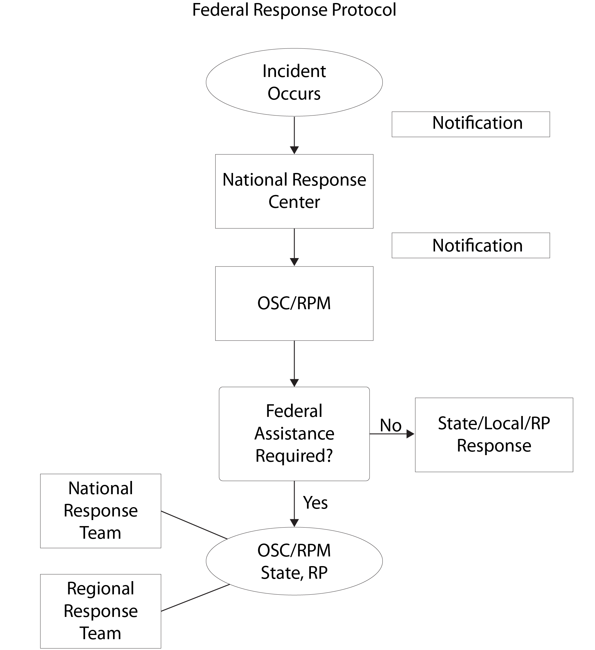
Product schedule
- The Clean Water Act requires EPA to maintain a list of dispersants, chemicals, and other substances that can be used to respond to an oil spill.
Section 311(d)(2) of the Clean Water Act (CWA), as amended by 4201(a) of the Oil Pollution Act (OPA), mandates that the Environmental Protection Agency (EPA) maintain a list of dispersants, chemicals, and other substances that can be used to respond to an oil discharge. Regulations for the implementation of this list, the NCP Product Schedule, are codified in 40 CFR 300 Subpart J. Similarly, a separate list of sorbent materials are found in the NCP Sorbent Product List, in accordance with Subpart J.
NCP Product Schedule
Products for which EPA received submission packages that meet Subpart J data and information requirements, and for which the agency has made an affirmative listing determination, are included in the NCP Product Schedule. Products on the NCP Product Schedule are grouped into the following categories:
- Bioremediation agents — Microorganisms, enzymes, and nutrient additives that increase the rate of biodegradation and mitigate any deleterious effects caused by the contaminant constituents.
- Dispersants — Substances that emulsify, disperse, or solubilize oil by promoting the formation of small droplets or particles of oil in the water column.
- Herding agents — Substances that form a film on the water surface to control the spreading of the oil to allow for oil removal.
- Surface washing agents — Substances that separate oil from solid surfaces, such as beaches, rocks, metals, or concrete, through a detergency mechanism that lifts and floats oil.
- Solidifiers — Substances that through a chemical reaction cause oil to become a cohesive mass, preventing oil from dissolving or dispersing into the water column.
The listing of a product does not mean that EPA approves, recommends, licenses, or certifies the use of the product on an oil discharge. It simply signifies that data have been submitted to EPA as required by Subpart J. Only a federal on-scene coordinator (OSC) may authorize use of the product in accordance with Subpart J in response to an oil discharge.
Note that herding agents, solidifiers, and surface washing agents listed on the NCP Product Schedule as of December 11, 2023, will remain conditionally listed until June 10, 2026, provided that no products are listed on the new NCP Product Schedule in these categories as of December 12, 2025. On June 10, 2026, all conditionally listed products that have not been submitted and listed in the new NCP Product Schedule based on the latest Subpart J testing and listing criteria will be removed.
NCP Sorbent Product List
The NCP Sorbent Product List identifies known sorbent materials and products. It serves as reference for the OSC when considering the use of such products for responding to an oil discharge. In fact, response actions, including the use of sorbents, are subject to OSC oversight under the NCP.
Sorbent products that consist solely of the following materials (as found at 300.915(g)(1)), or any combination thereof, are generically listed on the Sorbent Product List, even if not identified by a brand or trademark:
- Feathers, cork, peat moss, and cellulose fibers, such as bagasse, corncobs, and straw;
- Volcanic ash, perlite, vermiculite, zeolite, and clay; and
- Polypropylene, polyethylene, polyurethane, and polyester.
A specific listing of sorbent products with a name, brand, or trademark in accordance with 300.915(g)(1) are based solely on the submitter’s representation of constituents in the product, and do NOT represent a determination made by EPA.
Other sorbent products not specifically identified under 300.915(g)(1) are subject to EPA review and approval prior to listing on the Sorbent Product List. They can consist of one or more natural organic substances, inorganic/mineral compounds, and/or synthetic compounds, that the product submitter believes meet the definition of a sorbent.
Oil discharge reporting
- Any discharge of oil in a harmful quantity that reaches a navigable waterway or adjoining shoreline must be reported according to federal reporting requirements.
Whether an oil discharge originates from a vessel, offshore facility, or onshore facility, it is reportable under Part 110 if a harmful quantity is discharged. See Covered Facilities to learn more about the applicability criteria and exemptions under Part 110. A subset of these oil discharges is also reportable under Part 112. Also, 300.300 includes discovery and notification regulations for discharges of oil.
Reporting under Part 110
If a facility or vessel discharges oil to navigable waters or adjoining shorelines, the facility is required to follow certain federal reporting requirements. Section 311(b)(3) of the Clean Water Act (CWA) stipulates notification is required when a “harmful quantity” of oil is discharged into the navigable waters or adjoining shorelines of the U.S. Pursuant to CWA 311(b)(3), release notification regulations for discharges of oil are codified in Part 110 of the Environmental Protection Agency (EPA) regulations.
Section 110.3 clarifies that a discharge of a harmful quantity of oil is one that violates applicable water quality standards, causes a film or sheen upon or discoloration of the surface of the navigable water or adjoining shorelines, or causes sludge or emulsion to be deposited beneath the surface of the navigable water or upon the adjoining shorelines. A few exemptions are listed at section 110.5.
According to section 110.6, persons in charge of a facility or vessel must immediately notify the National Response Center (NRC) as soon as they have knowledge of a non-exempt discharge of oil from that facility or vessel in a harmful quantity amount.
The contact number for the NRC is (800) 424-8802 or (202) 267-2675. The NRC is the federal government's centralized reporting center, which is staffed 24 hours a day by U.S. Coast Guard personnel.
If reporting directly to NRC is not practicable, reports also can be made to the EPA regional office or the USCG Marine Safety Office (MSO) in the area where the incident occurred.
The following information will be requested by the NRC (or EPA regional office):
- The exact address or location and phone number of the facility;
- The date and time of the discharge, the type of material discharged;
- Estimates of the total quantity discharged;
- Estimates of the quantity discharged to navigable waters or adjoining shorelines;
- The source of the discharge;
- A description of all affected media;
- The cause of the discharge;
- Any damages or injuries caused by the discharge;
- Actions being used to stop, remove, and mitigate the effects of the discharge;
- Whether an evacuation may be needed; and
- The names of individuals and/or organizations who have also been contacted.
Reporting under Part 112
Any owner or operator of a non-transportation-related facility regulated by the spill prevention, control, and countermeasure (SPCC) rule (Part 112 Subparts A to C) must submit a report to the Environmental Protection Agency (EPA) Regional Administrator within 60 days when:
- More than 1,000 U.S. gallons of oil is discharged to navigable waters or adjoining shorelines in a single event; or
- More than 42 U.S. gallons of oil in each of two discharges to navigable waters or adjoining shorelines occurs within any 12-month period.
Note that the gallon amount(s) specified (either 1,000 or 42) refers to the amount of oil that actually reaches navigable waters or adjoining shorelines, not the total amount of oil spilled. EPA considers the entire volume of the discharge to be oil for the purposes of these reporting requirements.
The written report to the EPA Regional Administrator must include the following:
- Name and location of the facility;
- Owner or operator name;
- Maximum storage or handling capacity of the facility and normal daily throughput;
- Corrective actions and countermeasures taken, including descriptions of equipment repairs and replacements;
- Adequate description of the facility, including maps, flow diagrams, and topographical maps, as necessary;
- Cause of the discharge to navigable waters, including a failure analysis;
- Failure analysis of the system where the discharge occurred;
- Additional preventive measures taken or planned to take to minimize discharge reoccurrence.
The facility must send a copy of the above information to the agency or agencies in charge of oil pollution control activities in the state in which the SPCC-regulated facility is located.
After reviewing the information, the EPA Regional Administrator may require additional information and/or an amendment to the SPCC Plan. If a facility wishes to appeal a decision made by the Regional Administrator requiring an amendment to an SPCC Plan, the facility should follow the requirements at 112.4(f).
Reporting under Part 300.300
In September 1994, EPA codified revisions to the National Contingency Plan (NCP) at Part 300.300 that included discovery and notification regulations for discharges of oil. These revisions clarify that a discharge of oil may be discovered by a report from the person in charge of a vessel or facility, a deliberate search by patrols, a random or incidental observation by government agencies or the public, or other sources. The notification provisions of this section require any person, upon the discovery of a discharge of oil, to notify the National Response Center (NRC). The NRC must then promptly notify the federal On-Scene Coordinator (OSC), who must notify the appropriate state agency of any states that may be affected by the discharge. The OSC shall then proceed with the following phases as outlined in the RCP and ACP.
Discharge response and cleanup
- Response to an oil spill will depend on the type of oil discharged, the location of the spill and its proximity to sensitive environments, and other factors.
- Containment equipment is used to contain a spill, while chemical and biological methods can help with removal and dispersal of the oil.
Response to oil spills requires the combined efforts of the owner or operator of the facility or vessel that spilled the oil, the federal On-Scene Coordinator (OSC), and/or state and local government officials. The specific steps taken to respond to a spill depend not only on the response plans that were prepared before the spill but also on the type of oil discharged, the location of the discharge, the proximity of the spill to sensitive environments, and other environmental factors.
When an oil spill occurs on water, it is critical to contain the spill as quickly as possible in order to minimize danger and potential damage to people, property, and natural resources. Containment equipment is used to restrict the spread of oil and to allow for its recovery, removal, or dispersal. The most common type of equipment used to control the spread of oil is the floating barrier, called a boom.
Chemical and biological methods can be used in conjunction with mechanical means for containing and cleaning up oil spills. Dispersants are most useful in helping to keep oil from reaching shorelines and other sensitive habitats. Biological agents have the potential to assist recovery in sensitive areas such as shorelines, marshes, and wetlands. In-situ burning has shown the potential to be an effective cleanup method under certain circumstances. Research into these technologies continues in the hope that future oil spills can be contained and cleaned up more efficiently and effectively.
Despite the best efforts of response teams to contain spilled oil, some of it may contaminate shorelines of oceans and lakes, banks of rivers and streams, and other ecologically sensitive habitats along the water’s edge. To help protect these resources from damage and to preserve them for public enjoyment and for the survival of numerous species, cleaning up shorelines following oil spills has become an important part of oil spill response.
Factors that affect the type of cleanup method used include the type of oil spilled, the geology of the shoreline and rate of water flow, and the type and sensitivity of biological communities in the area. Natural processes, such as evaporation, oxidation, and biodegradation help to clean the shoreline. Physical methods, such as wiping with sorbent materials, pressure washing, and raking and bulldozing can be used to assist these natural processes.
Cleanup from an oil spill is not considered complete until all waste materials are disposed of properly. The cleanup of an oiled shoreline can create different types of waste materials, including liquid oil, oil mixed with sand, and tar balls. Oil can sometimes be recovered and reused, disposed of by incineration, or placed in a landfill. States and the federal government strictly regulate the disposal of oil.
Oil collected during cleanup activities must be reused or disposed of properly, using such methods as incineration or landfilling. Choosing the most effective yet potentially least damaging cleaning methods helps to ensure that the natural systems of shorelines and the recreational benefits they offer will be preserved and protected for future generations.
Cleanup liability and funding
- When an oil spill occurs, the EPA has the authority to require a responsible party to pay for the cleanup and to compensate for lost or damaged natural resources.
The Clean Water Act (CWA) liability provisions, as amended by the Oil Pollution Act (OPA), provide the Environmental Protection Agency (EPA) the authority to require a responsible party (RP) to pay for cleanup and compensate for lost or damaged natural resources. Since EPA has limited funding for the cleanup of oil, it is important that EPA receive compensation and recovery of funds they use when responding to oil discharge events.
OPA section 1002 specifically outlines the costs for which an RP can be held liable, including removal costs and the costs of other actions taken to mitigate damage to public health and welfare. Additionally, an RP can be held liable for damages such as real or personal property damages, the costs of assessing natural resource damages, loss of profits or earning capacity, and the net cost of additional public services provided during or after removal actions.
Similar to liability under the Comprehensive Environmental Response, Compensation, and Liability Act (CERCLA), OPA liability is judicially interpreted as both strict and joint and several. Strict liability is the assessment of legal responsibility without regard to fault or diligence. Joint and several liability means that any entity considered an RP can be held liable for the entire cleanup, regardless of his or her contribution to the discharge.
Financial responsibility
In preparation for an oil spill, section 2716 of the Oil Pollution Act (OPA) specifies financial responsibility requirements for offshore facilities. Financial responsibility is the ability to pay for cleanup or third-party liability compensation that results from an oil discharge. Financial responsibility ensures the timely completion of corrective action and third-party compensation and thus reduces the risk to human health and the environment posed by oil discharges. It also may provide an incentive for operating practices that can prevent leaks, overfills, and spills.
Under OPA, the owner or operator of a facility from which oil is discharged (responsible party) is liable for the costs associated with the:
- Containment
- Cleanup
- Damages resulting from the spill
Oil Spill Liability Trust Fund
In the event of an oil discharge, EPA prefers to have RPs finance the cleanup of their own oil discharges. When the RP is unknown or refuses to pay, the Oil Spill Liability Trust Fund (the Fund) can cover removal costs and/or damages that are not recovered from that RP. The emergency response portion of the Fund is administered by the U.S. Coast Guard's National Pollution Funds Center (NPFC).
The Fund can provide up to $1 billion for any one oil pollution incident, including up to $500 million for the initiation of natural resource damage assessments and claims in connection with any single incident (Internal Revenue Code, as amended by the OPA; 26 USC 9509). OPA section 1012 delineates the allowable uses of the Fund, including:
- Payment of costs assumed by states for removal actions conducted in a manner consistent with the National Contingency Plan (NCP);
- Payments to federal, state and Native American tribe trustees to carry out natural resource damage assessments and restorations in a manner consistent with the NCP;
- Payment of claims for uncompensated removal costs and damages; and
- Research and development and other specific appropriations.
The primary source of revenue for the Fund was a five-cents-per-barrel tax on imported and domestic oil. This tax expired on December 31, 1994. Several new laws since then have reinstated the tax and/or raised the tax to eight cents per barrel, but these taxes have since expired also. Current revenue sources for the Fund include interest on the Fund, cost recovery from the parties responsible for discharges, and fines or civil penalties collected from RPs.
Penalties
- Criminal and civil penalties may be enforced against facilities that violate prevention, response, and notification regulations regarding oil spills.
The Environmental Protection Agency (EPA) regulates the prevention, response, and notification of oil spills that reach navigable water and/or adjoining shorelines. This authority comes from both the Clean Water Act (CWA) and the Oil Pollution Act (OPA). However, a facility owner or operator should know that there may be criminal and civil penalties for violating the regulations.
Criminal penalties
Per 33 U.S.C. 1319(c)(1) and (2) and 1321(b)(3), a person found guilty of negligently or knowingly discharging oil in a harmful quantity into a water of the U.S. or upon adjoining shorelines or into the contiguous zone, may face the following penalties:
- Negligent Violations: One year and/or $2,500–$25,000 per day; Subsequent convictions two years and/or $50,000 per day.
- Knowing Violations: Three years and/or $5,000–$50,000 per day; Subsequent convictions six years and/or $100,000 per day.
A person in charge of an onshore or offshore facility who fails to immediately notify the appropriate federal agency as soon as that person has knowledge of oil that is discharged in a reportable (harmful) quantity into or upon waters of the United States, upon adjoining shorelines, or into the Contiguous Zone may face five years and/or fines under 18 U.S.C. 3571 (see 33 U.S.C. 1321(b)(5)).
Civil penalties
Section 311(b)(3) of the CWA prohibits the discharge of threshold amounts of oil or hazardous substances to navigable waters of the U.S. To reduce the likelihood of a mishap, regulations issued under section 311(j) (published at Part 112) require facilities that store oil in significant amounts to prepare spill prevention plans and to adopt certain measures to keep accidental releases from reaching navigable waters. Certain types of facilities that pose a greater risk of release must also develop plans to respond promptly to clean up any spills that do occur.
Sections 311(b)(6) and (7) of the CWA, also found at 33 U.S.C. 1321(b)(6) and (7), authorize civil penalties for violation of any of these requirements. The penalty monies are deposited in the Oil Spill Liability Trust Fund, administered by the U.S. Coast Guard, and are used to help cover any spill cleanup costs incurred by the government. Civil penalties reduce the likelihood of a spill by providing an incentive to the violator and to other members of the regulated community to comply with the Act’s requirements, help replenish funds that are used to clean up the environment, and provide a level playing field for businesses that meet their obligations under the law.
OPA increased penalties for violations of Section 311 of the CWA. In administrative cases, Section 311(b)(6) of the Act, as amended, 33 U.S.C. 1321(b)(6), authorizes EPA to assess Class I or Class II administrative penalties for the violation of section 311(b)(3) or section 311(j). A Class I penalty may be assessed in an amount of up to $10,000 per violation, not to exceed $25,000. For liability purposes each violation should also be tabulated on a daily basis. A Class II penalty may be assessed in an amount of up to $10,000 per day of violation, not to exceed $125,000.
However, the above have been increased by 10 percent, for events occurring after January 30, 1997, by the Debt Collection Improvement Act of 1996 (DCIA) and its implementing regulations published at Part 19. Future across-the-board inflation adjustments under the DCIA are to be published not less often than every four years. EPA typically publishes annual increases to civil penalty amounts in January.
Under Part 19, the penalty amounts as enacted and as amended for inflation are as follows:
| Statute | Description | Statutory civil monetary penalties for violations that occur or occurred after November 2, 2015, where penalties are assessed on or after January 8, 2025 | Statutory civil monetary penalties, as enacted |
|---|---|---|---|
| 33 U.S.C. 1321(b)(6)(B)(i) | Oil discharged in violation or fails/refuses to comply with (j). Maximum penalty for class I. | 23,647/59,114 | 10,000/25,000 |
| 33 U.S.C. 1321(b)(6)(B)(ii) | Maximum penalty for class II. | 23,647/295,564 | 10,000/125,000 |
| 33 U.S.C. 1321(b)(7)(A) | Oil discharged in violation. Maximum penalty per day OR penalty per barrel or reportable unit. | 59,114/2,364 | 25,000/1,000 |
| 33 U.S.C. 1321(b)(7)(B) | Failure to remove discharge or failure to comply with order. Maximum penalty per day. | 59,114 | 25,000 |
| 33 U.S.C. 1321(b)(7)(C) | Fails or refuses to comply with any regulation under (j). Maximum penalty per day. | 59,114 | 25,000 |
| 33 U.S.C. 1321(b)(7)(D) | Gross negligence or willful misconduct. Minimum penalty $ and not more than $ per barrel or unit of reportable quantity. | 236,451/7,093 | 100,000/3,000 |
OPA also established additional judicial sanctions. A person who violates section 311(b)(3) of the Clean Water Act is subject to a civil penalty of up to $25,000 per day of violation, or up to $1,000 per barrel of oil or per unit of reportable quantity of CWA-listed hazardous substance discharged. In instances of gross negligence or willful misconduct, these penalties increase to a $100,000 minimum and a maximum of $3,000 per barrel or unit of reportable quantity discharged.
EPA interprets this to mean that in the judicial forum the government may elect whether per day or volumetric penalties may apply according to how it pleads its case, or plead both approaches in the alternative. The law also provides that a person subject to regulations implementing the spill prevention and response program of section 311(j) of the Act may be assessed civil penalties of up to $25,000 per day of violation.
Important guidance and policy documents
- A list of resources and reference material on oil spill prevention follows in this section.
The following references may be consulted for further guidance and policy on oil spill prevention:
- Certification of the Applicability of the Substantial Harm Criteria; Attachment C-II; Found in Appendix C to Part 112
- Common SPCC and FRP Deficiencies: Summary of Findings; EPA webinar slides – 4/2021
- Compliance Concerns Associated with Increasing Oil Storage; EPA compliance advisory EPA 305-F-20-003 – 10/2020
- Facility Response Planning: Compliance Assistance Guide; EPA publication EPA 540-K-02-003d – 8/2002
- Facility-specific Response Plan; Appendix F to Part 112
- Failures of Overfill Prevention at Substantial Harm Oil Facilities During Marine Vessel and Pipeline High-Volume Oil Transfer Operations; EPA technical alert EPA 540-S-24-001 – 8/2024
- Flowchart for the Criteria for Substantial Harm; Attachment C-I; Found in Appendix C to Part 112
- Guidance for Listing Products on the NCP Product Schedule or NCP Sorbent Product List; EPA 550-B-24-002 – 6/11/2024
- List of Petroleum and Non-petroleum Oils; U.S. Coast Guard document with contact Mr. Patrick Keffler, CG-ENG-5, at (202) 372-1424 – modified 3/18/2013
- Memorandum of Understanding Between the Secretary of Transportation and the Administrator of the Environmental Protection Agency; Appendix A to Part 112
- National Contingency Plan Subpart J; EPA topic webpage
- National Oil and Hazardous Substances Pollution Contingency Plan (NCP) Sorbent Product List; EPA topic webpage
- NCP Product Schedule (Products Available for Use on Oil Spills); EPA topic webpage
- NRT-RRT Factsheet: Application of Sorbents and Solidifiers for Oil Spills; National Response Team document – 2/2007
- Oil Discharge Reporting Requirements: How to Report Oil Discharges to the National Response Center and EPA; EPA publication EPA-550-F-06-006 – 12/2006
- Oil Spills Prevention and Preparedness Regulations; EPA topic webpage
- Oil Storage on U.S. Farms: Risks and Opportunities for Protecting Surface Waters; EPA publication EPA-530-R-15-002 – 6/30/2015
- Public Safety at Oil and Gas Upstream Facilities; EPA safety alert EPA 540B20001 – 3/2021
- Quality and Consistency Review of SPCC and FRP Plans: Summary of Findings; EPA document – 4/7/2021
- Qualified Facilities Applicability; EPA guidance – 4/2011
- Sample SPCC Plan for a Marina; EPA Region 5 document – 1/2002
- Secondary Containment Calculation Worksheets; EPA webpage
- Spill Prevention, Control and Countermeasure Practices at Small Petroleum Facilities: Interagency Energy/Environment R&D Program Report; EPA-600/7-80-004 – 1/1980
- Spill Prevention, Control, and Countermeasure (SPCC) Regulation Part 112: A Facility Owner/Operator’s Guide to Oil Pollution Prevention; EPA publication EPA 540-K-09-001 – 6/2010
- SPCC Bulk Storage Container Inspection Fact Sheet; EPA fact sheet – 8/2013
- SPCC Guidance for Regional Inspectors; EPA publication EPA 550-B-13-002 - 12/16/2013
- SPCC Streamlined Requirements for Tier I and II Qualified Facilities; EPA fact sheet – 5/2011
- Subpart J: The National Oil and Hazardous Substances Pollution Contingency Plan (NCP) Product Schedule; EPA publication EPA-550-F-06-002 – 10/2007
- Substantial Harm Criteria; Appendix C to Part 112
- Tier I Qualified Facility SPCC Plan; Appendix G to Part 112
- Tier I Qualified Facility SPCC Plan Template; EPA document – 2/2011
- Types of Oil; EPA topic webpage
- Understanding Oil Spills and Oil Spill Response; EPA publication EPA 540-K-99-007 – 12/1999
- When Are You Required to Report an Oil Spill and Hazardous Substance Release?; EPA webpage
State and local requirements
- While federal regulations apply in all U.S. states and territories, those states and territories may have their own additional requirements and penalties related to oil spill prevention and reporting.
The federal regulations at 40 CFR 112 for oil spill prevention and response and 40 CFR 110 for oil discharge notification apply in all states and territories. However, these federal regulations do not preempt state and territorial law. That means states and territories may impose additional requirements and penalties for covered facilities.
Oil spill reporting
A common misunderstanding is that by reporting a discharge to the National Response Center (NRC) a facility has met state and local reporting requirements. However, the report to the NRC only satisfies federal reporting requirements under Part 110. Additional state and local reporting requirements may apply.
Similarly, an oil spill reported to federal EPA under Part 112 only satisfies those federal reporting requirements. Additional state and local reporting requirements may apply.
Oil spill prevention, control, and countermeasure (SPCC)
Unlike some other federal environmental programs, the Clean Water Act does not authorize EPA to delegate the oil SPCC program implementation or enforcement to state, local, or tribal representatives. Therefore, any state, territory, local, or tribal laws and regulations on oil spill prevention, control, and countermeasure cannot preempt federal SPCC requirements at 40 CFR 112. Put another way, covered facilities in all U.S. locations must meet federal SPCC regulations. States, territories, localities, and tribes may, however, add other and/or more stringent requirements in those jurisdictions.
What's more, section 112.7 also says, “You must also address in your Plan: ... Contact list and phone numbers for ... all appropriate Federal, State, and local agencies who must be contacted in case of a discharge as described in 112.1(b) ... In addition to the minimal prevention standards listed under this section, include in your Plan a complete discussion of conformance with the applicable requirements and other effective discharge prevention and containment procedures listed in this part or any applicable more stringent state rules, regulations, and guidelines.”
Therefore, it’s important not only to comply with federal regulations but to also look for and comply with any additional and more stringent requirements of the states, territories, localities, and tribal lands in which a facility is located. To be compliant with all authorities having jurisdiction, check with your state, territory, local, or tribal agencies for more information.
Adopted consensus standards
It is also worth noting that state and local codes may adopt certain national and even international voluntary consensus standards, which may call for more stringent controls. When they are adopted into state and local codes, these otherwise voluntary standards become mandatory. For example, many states and localities adopt NFPA 30, Flammable and Combustible Liquids Code, making applicable containers of flammable liquids subject to provisions of this standard from the National Fire Protection Association.
Covered facilities
- Facility owners/operators need to understand when their facilities are required to report (Part 110) and to prevent and respond to (Part 112) an oil spill.
It’s important for a facility owner or operator to know when a facility falls under the oil discharge notification requirements at Part 110 and the oil pollution prevention and response requirements at Part 112. Failure to comply when required may result in criminal sanctions under the Clean Water Act (CWA). On the flip side, there’s no penalty for reporting unnecessarily under Part 110, and complying with the oil pollution prevention and response requirements of Part 112 when not required may add needless burdens to the facility’s operations.
Part 110 applicability determination
- Notification is required whenever a harmful quantity of oil is discharged, and when that oil reaches navigable waters or adjoining shorelines in the U.S.
The Environmental Protection Agency (EPA) strives to limit the damage done by oil spills through regulations at Part 110 requiring the immediate notification of a discharge of a harmful quantity of oil.
Section 311(b)(3) of the Clean Water Act (CWA) stipulates notification is required when two criteria are met:
- A “harmful quantity” of oil is discharged; and
- That oil discharge is into the navigable waters or adjoining shorelines of the U.S.
Pursuant to CWA section 311(b)(3), release notification regulations for discharges of oil were codified in Part 110 on April 2, 1987. Section 110.3 clarifies that a discharge of a harmful quantity of oil is one that:
- Causes a film or sheen upon or discoloration of the surface of the navigable water or adjoining shorelines,
- Causes sludge or emulsion to be deposited beneath the surface of the navigable water or upon the adjoining shorelines, or
- Violates applicable water quality standards.
The appearance of a “sheen” on the surface of the water is often used as a simple way to identify harmful discharges of oil that must be reported. However, the presence of a sludge or emulsion or of another deposit of oil beneath the water surface, or the violation of an applicable water quality standard, also indicates a harmful discharge regardless of whether there is a sheen on the water surface.
Sludge means an aggregate of oil or oil and other matter of any kind in any form other than dredged spoil having a combined specific gravity equivalent to or greater than water. Water quality standards define the goals for a water body by designating its uses, setting criteria to protect those uses, and establishing provisions such as antidegradation policies to protect water bodies from pollutants.
Addition of any chemical or biological agent, or any other substance, to oil to be discharged that would circumvent the provisions of Part 110 is prohibited.
Exemptions
- Exemptions to reporting requirements exist when oil spills to do not reach navigable waters or adjoining shorelines; when oil is released from a properly functioning vessel engine; for certain approved research and demonstration purposes; and a few others.
Several types of oil spills do not need to be reported.
Discharges that did not reach navigable waters or adjoining shorelines
If a discharge has not reached navigable waters or adjoining shorelines, it is not reportable. For example, if a tank leaks a puddle of oil into a building’s basement, this would be considered a discharge of oil, but it is not reportable if the oil did not reach a navigable water or adjoining shoreline. However, groundwater may be a conduit to navigable water or an adjoining shoreline.
Properly functioning vessel engines
Discharges of oil from a properly functioning vessel engine are not deemed to be harmful; therefore, they do not need to be reported under the Discharge of Oil Standard. However, oil accumulated in a vessel's bilge is not exempt.
Research and development releases
The Environmental Protection Agency (EPA) may permit the discharge of oil on a case-by-case basis in connection with:
- Research,
- Demonstration projects, or
- Studies relating to the prevention, control, or abatement of oil pollution.
However, the Discharge of Oil Standard specifically forbids the use of any chemical or biological agent, or any other substance, to circumvent the standard.
NPDES-permitted releases
Three types of discharges subject to the National Pollutant Discharge Elimination System (NPDES) are exempt from oil spill reporting:
- Discharges in compliance with a permit under section 402 of the Clean Water Act (CWA), when the permit contains either an effluent limitation:
- Specifically applicable to oil, or
- Applicable to another parameter that has been designated as an indicator of oil.
- Discharges resulting from circumstances identified and reviewed and made part of the public record with respect to a permit issued or modified under section 402 of the CWA, and subject to a condition in such permit. This exclusion addresses situations where the source, nature, and amount of a potential oil discharge was identified, and a treatment system capable of preventing that discharge was made a permit requirement.
For example, if a discharger has a drainage system that will route spilled oil from a broken hose connection to a holding tank for subsequent treatment and discharge, the treatment system must be sufficient to handle the maximum potential spill from that source. Spills larger than those contemplated in the public record are not exempted. - Continuous or anticipated intermittent discharges from a point source, identified in a permit or permit application under section 402 of the CWA, which are caused by events occurring within the scope of relevant operating or treatment systems. This exclusion applies to chronic or anticipated intermittent discharges originating in the manufacturing or treatment systems of a facility or vessel, including those caused by periodic system failures. Discharges caused by spills or episodic events that release oil to the manufacturing or treatment systems are not exempt from reporting.
Discharges permitted under MARPOL
Certain discharges beyond the territorial seas (defined as extending three miles seaward from the coast) are allowed if they are permitted under international law. The International Convention for the Prevention of Pollution from Ships (MARPOL), as amended, prohibits the discharge of oily mixtures (defined as mixtures with any oil content) from a tanker except when all of the following conditions are met:
- The tanker is proceeding en route,
- The tanker is more than 50 miles from the nearest land,
- The instantaneous rate of discharge does not exceed 60 liters per mile, and
- The total quantity of oil discharged in any ballast voyage does not exceed 1/15,000 of the total cargo carrying capacity.
In addition, MARPOL allows discharges in quantities verified by a monitoring system to be less than or equal to 15 parts per million, regardless of whether the discharge causes a sheen. Therefore, discharges permitted under MARPOL into waters seaward of the territorial sea are exempt from U.S. oil spill notification requirements. Such discharges may include the operational discharge of limited quantities of oil-water mixtures from ships.
Part 112 applicability determination
- A facility is covered by the Oil Pollution Prevention Standard (Part 112) if the facility is non-transportation-related; is engaged in certain oil-related activities; could discharge oil in harmful quantities; and has a certain oil storage capacity.
The Environmental Protection Agency (EPA)’s Oil Pollution Prevention Standard strives to limit damage done by oil spills through regulations designed to address a facility's preparedness and its ability to prevent and respond to an oil discharge.
General applicability criteria
The Oil Pollution Prevention Standard at Part 112 applies to facility owners or operators if:
- The facility or part of the facility is considered non-transportation-related; and
- The facility is engaged in drilling, producing, gathering, storing, processing, refining, transferring, distributing, using, or consuming oil or oil products; and
- The facility could reasonably be expected to discharge oil in quantities that may be harmful, and the discharge is to U.S. navigable waters or adjoining shorelines; and
- The facility meets at least one of the following capacity thresholds:
- Aboveground oil storage capacity greater than 1,320 U.S. gallons, or
- Completely buried oil storage capacity greater than 42,000 U.S. gallons.
Below is a flowchart with all four criteria:
Facilities that are owned and operated by federal, state, or local government or tribal entities are equally subject to the regulation as any other facility (although the federal government is not subject to civil penalties).
Activities involving oil
- Some activities that are considered to be oil-related activities include: drilling, producing, gathering, storing, processing, refining, transferring, distributing, or consuming oil or oil products.
Paragraph (b) to Part 112.1 specifies the following oil-related activities are regulated: drilling, producing, gathering, storing, processing, refining, transferring, distributing, using, or consuming oil and oil products. That means these activities are subject to the Oil Pollution Prevention Standard provided the facility meets the other applicability criteria in section 112.1. The table provides examples of these activities.
| Oil-related activity | Examples |
|---|---|
| Drilling | Drilling a well to extract crude oil or natural gas and associated products (such as wet natural gas) from a subsurface field |
| Producing | Extracting product from a well and separating the crude oil and/or gas from other associated products (e.g., water, sediment) |
| Gathering | Collecting oil from numerous wells, tank batteries, or platforms and transporting it to a main storage facility, processing plant, or shipping point |
| Storing | Storing oil in containers prior to use, while being used, or prior to further distribution in commerce |
| Processing | Treating oil using a series of processes to prepare the oil for commercial use, consumption, further refining, manufacturing, or distribution |
| Refining |
|
| Transferring | Transferring oil between containers, such as between a railcar or tank truck and a bulk storage container, or between stock tanks and manufacturing equipment |
| Distributing | Selling or marketing oil for further commerce or moving oil using equipment such as highway vehicles, railroad cars, or pipeline systems in the confines of a non-transportation-related facility. Note that businesses commonly referred to as oil distributors and retailers are also “storing” oil, as described in this table |
| Using | Using oil for mechanical or operational purposes in a manner that does not significantly reduce the quantity of oil, such as using oil to lubricate moving parts, provide insulation, or for other purposes in electrical equipment, electrical transformers, and hydraulic equipment |
| Consuming | Consuming oil in a manner that reduces the amount of oil, such as burning as fuel in a generator |
Container types
- Facilities are subject to Part 112 if they have oil in aboveground containers; buried tanks; containers used for seasonal or temporary storage; or tanks that are partially buried or contained in a vault.
Under subparagraphs 112.1(b)(1) through (4), the Oil Pollution Prevention Standard is applicable to eligible facilities that have oil in:
- Aboveground containers;
- Completely buried tanks;
- Containers that are used for standby storage, for seasonal storage, or for temporary storage, or are not otherwise “permanently closed;” and
- “Bunkered tanks” or “partially buried tanks” or containers in a vault.
Containers include not only oil storage tanks, but also mobile or portable containers such as drums and totes, and oil-filled equipment such as electrical equipment (e.g., transformers and circuit breakers), manufacturing flow-through process equipment, and operational equipment.
Storage capacity thresholds
- Part 112 applies to facilities with oil capacity of more than 42,000 gallons stored underground, or more than 1,320 gallons stored aboveground.
Subparagraph 112.1(d)(2) of the Oil Pollution Prevention Standard limits the applicability to facilities with oil capacity above certain threshold amounts. Specifically, Part 112 applies to a facility that has more than 42,000 U.S. gallons of completely buried oil storage capacity or more than 1,320 U.S. gallons of aggregate aboveground oil storage capacity, provided the facility meets the other applicable criteria set forth in 112.1.
Once a facility is subject to the regulation, all aboveground containers and completely buried tanks are subject to the requirements (unless these containers are otherwise exempt from the regulation). For example, a facility could have 10,000 U.S. gallons of aggregate aboveground storage capacity in tanks and oil-filled equipment of 55 U.S. gallons or more, and a completely buried tank of 10,000 U.S. gallons that is not subject to all of the technical requirements of Part 280 or a state program approved under Part 281 (and therefore not exempt). Since the aboveground storage capacity exceeds 1,320 U.S. gallons, all of the tanks and oil-filled equipment, including the buried tank, are subject to the Spill Prevention, Control, and Countermeasure (SPCC) rule.
Subparagraphs 112.1(d)(2)(i) and (ii) clarify which containers are included and excluded when calculating total storage capacity at a facility in determining whether it exceeds the volume limits in the regulation.
Under the Oil Pollution Prevention Standard, if a container has the requisite capacity, it does not matter whether the container is actually filled to that capacity. The storage capacity of a container is defined as the shell capacity of the container.
Facility boundaries
- Part 112 helps to define what constitutes a facility for the purposes of SPCC and FRP requirements. An owner or operator may not characterize a facility for the purpose of avoiding SPCC and FRP requirements.
A facility may or may not be subject to the Spill Prevention, Control, and Countermeasure (SPCC) and Facility Response Plan (FRP) rule requirements depending on how the facility owner or operator aggregates buildings, structures or equipment and associated storage or type of activity. However, once the owner/operator determines the facility boundaries for SPCC applicability, then the same boundaries apply for determining applicability of the FRP rule requirements. An owner or operator may not characterize a facility so as to simply avoid applicability of the rule (for example, defining separate facilities around oil storage containers that are located side-by-side or within close proximity, and are used for the same purpose).
A lease may, at the owner or operator’s discretion, constitute a facility but does not necessarily create a facility. According to the definition of facility, contiguous or noncontiguous buildings, properties, leases, structures, installations, pipes, or pipelines under the ownership or operation of the same person may be considered separate facilities. A facility may also consist of parcels that are smaller or larger than an individual lease.
The following factors to determine the boundaries of a facility are not exclusive and simply serve as examples:
- Ownership, management, and operation of the buildings, structures, equipment, installations, pipes, or pipelines on the site;
- Similarity in functions, operational characteristics, and types of activities occurring at the site;
- Adjacency; or
- Shared drainage pathways (e.g., same receiving water bodies).
Farm-specific applicability
- The WRRDA of 2014 changes the way the SPCC rule is applied to farms.
- New rules, when adopted by the EPA, will likely bring more farms under the SPCC rule.
Under the Spill Prevention, Control, and Countermeasure (SPCC) rule (Part 112 Subparts A to C), a farm is “a facility on a tract of land devoted to the production of crops or raising of animals, including fish, which produced and sold, or normally would have produced and sold, $1,000 or more of agricultural products during a year.”
Section 1049 of the Water Resources Reform and Development Act (WRRDA) of 2014 impacts the SPCC rule for farms. Specifically, the law changes certain applicability provisions of the SPCC rule for farms and modifies the criteria under which a farmer may self-certify an SPCC Plan. Details may be found at the following:
- The Environmental Protection Agency’s (EPA’s) fact sheet called “Oil Spill Prevention, Control, and Countermeasures (SPCC Program): Farms and the Water Resources Reform and Development Act (WRRDA),” April 24, 2015.
- EPA’s publication called “Oil Storage on U.S. Farms: Risks and Opportunities for Protecting Surface Waters,” EPA-530-R-15-002, June 30, 2015.
The changes are not yet in the regulations at Part 112. EPA expects to promulgate a rule amending the SPCC requirements associated with the applicability thresholds and other WRRDA amendments. However, please note that EPA has said it intends to lower the greater-than-6,000-gallon threshold to greater than 2,500 gallons. Lowering the threshold will bring more farms under the SPCC rule.
Exemptions
- EPA lists several exemptions from Part 112, most related to facility or equipment location, size, capacity, and more.
The Environmental Protection Agency (EPA) exempts the following from Part 112:
- Any facility, equipment, or operation that is not subject to the jurisdiction of EPA under section 311(j)(1)(C) of the Clean Water Act (CWA), as follows:
- Any onshore or offshore facility, that due to its location, could not reasonably be expected to have a discharge as described in 112.1(b). This determination must be based solely upon consideration of the geographical and location aspects of the facility (such as proximity to navigable waters or adjoining shorelines, land contour, drainage, etc.) and must exclude consideration of man-made features such as dikes, equipment, or other structures, which may serve to restrain, hinder, contain, or otherwise prevent a discharge as described in 112.1(b).
- Any equipment, or operation of a vessel or transportation-related onshore or offshore facility subject to the authority and control of the Department of Transportation (DOT), as defined in the memorandum of understanding found at Appendix A to Part 112.
- Any equipment, or operation of a vessel or onshore or offshore facility which is subject to the authority and control of the DOT or the Department of the Interior, as defined in the memorandum of understanding found at Appendix B to Part 112.
- Any facility where the completely buried oil storage capacity is 42,000 U.S. gallons or less AND the aggregate aboveground oil storage capacity is 1,320 U.S. gallons or less.
- Completely buried oil tanks and associated piping and equipment that are subject to all of the technical requirements under Part 280 or 281.
- Underground oil storage tanks, including below-grade vaulted tanks that supply emergency diesel generators at a nuclear power generation facility licensed by the Nuclear Regulatory Commission (NRC) and subject to any NRC provision regarding design and quality criteria, including, but not limited to, 10 CFR 50.
- Permanently closed oil containers.
- Any container with an oil storage capacity less than 55 U.S. gallons.
- Any facility or part thereof used exclusively for wastewater treatment and not used to satisfy Part 112 (the production, recovery, or recycling of oil is not wastewater treatment for the purposes of this exemption).
- Motive power oil containers (the transfer of fuel or other oil into a motive power container at an otherwise regulated facility is not eligible for this exemption).
- Hot-mix asphalt or any hot-mix asphalt container.
- Containers storing heating oil used solely at a single-family residence.
- Pesticide application equipment or related mix containers (with adjuvant oil).
- Intra-facility oil gathering lines subject to the regulatory requirements of 49 CFR 192 or 195, except that such a line’s location must be identified and marked as ‘‘exempt’’ on the facility diagram as provided in subparagraph 112.7(a)(3), if the facility is otherwise subject to Part 112.
- Any milk and milk product container and associated piping and appurtenance.
- Any offshore oil drilling, production, or workover facility that is subject to the notices and regulations of the Minerals Management Service (MMS), as specified in the Memorandum of Understanding found in Appendix B to Part 112. Note that MMS was replaced in 2011 by the Bureau of Ocean Energy Management (BOEM) and the Bureau of Safety and Environmental Enforcement (BSEE).
Facilities are not required to include exempt oil containers or oil equipment when calculating the total oil storage capacity of the facility.
Terms related to exemptions under Part 112
- Several exemptions exist for Part 112.
The quickest way for a facility to avoid having to comply with the Part 112 exemptions are discussed here.
Permanently closed
- If they meet the proper definition, permanently closed containers are exempt from Part 112 and no longer count toward a facility’s total oil storage capacity.
Permanently closed containers are exempt from Part 112. Once permanently closed, a container no longer counts toward the total facility storage capacity, nor is it subject to the other requirements under Part 112. Part 112 does not require that permanently closed containers be removed from a facility.
In addition, any container brought on to a facility that has never stored oil is not subject to Part 112, nor is it counted toward the facility capacity until it stores oil. Any other container that at one time stored oil but no longer contains oil or sludge, which is brought onto a facility and meets the definition of permanently closed, is not subject to Part 112 nor is it counted toward the facility capacity until it stores oil.
Permanent closure requirements under Part 112 are separate and distinct from the closure requirements in hazardous waste regulations promulgated under Subtitle C of the Resource Conservation and Recovery Act (RCRA), such as Part 264.197 and 265.197.
Is it really permanently closed?
Part 112 does not include a provision to temporarily close containers to account for seasonal use of tanks or variable economic conditions and production rates at oil production facilities. In order for a container to be exempt from Part 112 requirements, the container must meet the following criteria for a permanently closed container:
- All liquid and sludge have been removed from each container and connecting line;
- All connecting lines and piping have been disconnected from the container and blanked off;
- All valves (except ventilation valves) have been closed and locked; and
- Conspicuous signs have been posted on each container stating that it is a permanently closed container and noting the date of closure.
A permanently closed container may remain at the facility. However, a facility owner or operator should review state and local requirements, which may require removal of a container when it is taken out of service. When a container is removed from the facility, the Spill Prevention, Control, and Countermeasure (SPCC) Plan must be amended and the technical amendment must be certified.
In the event that a permanently closed container is brought back into use (e.g., to accommodate variations in production rates), the SPCC Plan will need to be amended to reflect the capacity of the permanently closed container if this capacity was previously excluded from the facility total capacity.
Underground storage tank
- Underground storage tanks are exempt from Part 112 but are subject to other regulations (such as Parts 280 and 281) that require a facility to prevent, detect, and clean up oil spills from such tanks.
Under subparagraph 112.1(d)(4), the Oil Pollution Prevention Standard exempts completely buried storage tanks, as well as connected underground piping, underground ancillary equipment, and containment systems, when such tanks are subject to all of the technical requirements of Part 280 or a state program approved under Part 281 (also known as the Underground Storage Tank (UST) regulations). Although these tanks are exempt from the requirements of Part 112, they must still be marked on the facility diagram if the facility is otherwise subject to the Spill Prevention, Control, and Countermeasure (SPCC) rule (see subparagraph 112.7(a)(3)).
The regulations at Part 280 and Part 281 comprise the UST Program, which requires owners and operators of new tanks and tanks already in the ground to prevent, detect, and clean up releases. Part 112 only recognizes a subset of tanks covered by the UST Program regulations. Specifically, the UST Program defines a UST as a tank and any underground piping that has at least 10 percent of its combined volume underground. However, under Part 112, only completely buried tanks subject to all of the technical UST program requirements are exempt from Part 112. Any tanks that are not completely buried are considered aboveground storage tanks and subject to Part 112.
The following completely buried tanks are either excluded from the definition of UST or are exempt from the UST regulations at Part 280 (and therefore may be subject to Part 112 if they contain oil):
- Tanks with a capacity of 110 U.S. gallons or less;
- Farm or residential tanks with a capacity of 1,100 U.S. gallons or less used for storing motor fuel for non-commercial purposes;
- Tanks used for storing heating oil for consumptive use on the premises where stored;
- Tanks storing non-petroleum oils, such as animal fat or vegetable oil;
- Tanks on or above the floor of underground areas (e.g., basements or tunnels);
- Septic tanks and systems for collecting stormwater and wastewater; •
- Flow-through process tanks;
- Emergency spill and overfill tanks that are expeditiously emptied after use;
- Surface impoundments, pits, ponds, or lagoons;
- Any UST system holding Resource Conservation and Recovery Act (RCRA) hazardous waste;
- Any equipment or machinery that contains regulated substances for operational purposes such as hydraulic lift tanks and electrical equipment tanks;
- Liquid trap or associated gathering lines directly related to oil or gas production or gathering operations;
- Pipeline facilities regulated under the Natural Gas Pipeline Safety Act of 1968, the Hazardous Liquid Pipeline Safety Act of 1979, or intrastate pipelines regulated under state laws comparable to the provisions of above laws; and
- Any UST system that contains de minimis concentration of regulated substances.
The following are examples of deferrals from the UST regulations (and therefore may be subject to Part 112):
- Wastewater treatment tank systems;
- Any UST systems containing radioactive materials that are regulated under the Atomic Energy Act of 1954;
- Airport hydrant fuel distribution systems; and
- UST systems with field-constructed tanks.
Note that, at an otherwise Part-112-regulated facility, any transfer to or from completely buried storage tanks is regulated because it is a potential source of discharge of oil into navigable waters or adjoining shorelines. Because a loading/unloading rack, or other transfer area, associated with a UST is not typically part of the UST system, it is not subject to all of the technical requirements of Part 280 or Part 281. Therefore, such a loading/unloading rack is regulated under the Part 112 regulations in the same manner as any other transfer equipment or transfer activity located at an otherwise Part-112-regulated facility.
Additional and/or more stringent requirements may exist in a state-approved program under Part 281, and they may also impact Part 112 applicability. For example, a state may choose to regulate a UST used for storing heating oil for consumptive use on the premises where stored. Thus, under the state program the UST is subject to all the technical requirements of a Part 281 program and therefore exempt from Part 112.
Wastewater treatment facilities
- The wastewater treatment exemption excludes from Part 112 those facilities or parts of facilities that are used exclusively for wastewater treatment.
The wastewater treatment exemption, outlined at Part 112.1(d)(6), excludes from the Part 112 requirements those facilities or parts of facilities that are used exclusively for wastewater treatment, and are not used to meet Part 112 requirements. Do not count the capacity of these exempt containers when calculating facility aggregate capacity.
Many of the wastewater treatment facilities or parts thereof are subject to the National Pollutant Discharge Elimination System (NPDES) or state-equivalent permitting requirements that involve operating and maintaining the facility to prevent discharges. The NPDES or state-equivalent process ensures review and approval of the facility’s plans and specifications; operation/maintenance manuals and procedures; and stormwater pollution prevention plans (SWPPPs), which may include best management practice (BMP) plans.
For the purposes of the exemption, the production, recovery, or recycling of oil is not considered wastewater treatment. These activities generally lack NPDES or state-equivalent permits and thus lack the protections that such permits provide. The goal of an oil production, oil recovery, or oil recycling facility is to maximize the production or recovery of oil, while eliminating impurities in the oil, including water, whereas the goal of a wastewater treatment facility is to purify water. Additionally, produced water is not considered wastewater and is therefore not eligible for this exemption. However, produced water containers used exclusively for wastewater treatment at dry gas production facilities are eligible for the wastewater treatment exemption.
The exemption also does not apply to a wastewater treatment facility (or part of that facility) that is used to store oil. In those instances, the oil storage capacity must be counted as part of the total facility storage capacity. For example, if there is a 1,000-gallon storage container that contains oil removed from an exempt oil/water separator and a 500-gallon storage container for an emergency generator, the total aboveground storage capacity for the facility would be 1,500 U.S. gallons, and the facility may potentially be regulated by Part 112.
A wastewater treatment facility (or parts of that facility) used to meet a Part 112 requirement, including an oil/water separator used to meet any spill prevention, control, and countermeasure (SPCC) requirement, is not exempt. Oil/water separators used to meet SPCC requirements include those used to satisfy the secondary containment requirements of subparagraphs 112.7(c), 112.7(h)(1), and/or 112.8(c)(2) or 112.8(c)(11). Although not exempt, oil/water separators used to satisfy secondary containment requirements of Part 112 do not count toward storage capacity.
Motive power
- A motive power container is defined as any onboard bulk storage container used primarily to power the movement of a motor vehicle, or ancillary onboard oil-filled operational equipment.
Motive power container means any onboard bulk storage container used primarily to power the movement of a motor vehicle, or ancillary onboard oil-filled operational equipment (Part 112.2). An onboard bulk storage container which is used to store or transfer oil for further distribution is not a motive power container. The definition of motive power container does not include oil drilling or workover equipment, including rigs.
Motive power containers on vehicles used solely at non-transportation-related facilities fall under the Environmental Protection Agency (EPA) jurisdiction but are exempt from Part 112. Section 112.1(d)(2)(ii) excludes the capacity of these containers from facility capacity calculations.
Bulk storage container used for propulsion
Containers on motor vehicles that provide the vehicle with a means of propulsion are considered motive power containers. Examples of motor vehicles which have containers used to individually provide their own means of propulsion from location to location within a facility or between facilities include:
- Aircraft,
- Cherry pickers,
- Self-propelled cranes,
- Self-propelled aviation ground service equipment vehicles,
- Self-propelled heavy vehicles (e.g., used in forestry, agricultural, mining, excavation and construction applications), and
- Locomotives.
Ancillary on-board equipment
Ancillary on-board equipment includes hydraulic and lubrication operational oil-filled containers used for other ancillary functions of a motor vehicle. It also includes motor vehicle bulk storage containers that serve a non-operational purpose in addition to the propulsion of the motor vehicle; for example, a bulk storage container that supplies fuel to an engine that provides the propulsion for that motor vehicle, as well as its auxiliary units and functions (e.g., heaters, air conditioning units, and electrical power generation, etc.).
Exclusions from the motive power container definition
The exemption does not include non-self-propelled stationary or towed equipment, such as towed ground service equipment or any type of oil-powered generator (gensets). The following are examples of equipment that are not motive power containers because they do not include containers used for propulsion: •
- Towed aviation ground service equipment,
- Non-self-propelled construction/cargo cranes,
- Non-self-propelled (forestry, agricultural, mining, excavation or construction) equipment,
- Oil-powered generators,
- Fire pumps, and
- Compressors.
An onboard bulk storage container used to store or transfer oil for further distribution is also not a motive power container. An onboard bulk storage container that supplies oil for the movement of a vehicle or operation of onboard equipment, and at the same time is used for the distribution or storage of this oil is not eligible for the exemption. This situation includes, for example, a mobile refueler that has an onboard bulk storage container used to distribute fuel to other vehicles on a site and which also draws its engine fuel (for propulsion) from that bulk container.
Oil drilling and workover equipment (including rigs) are not eligible for the motive power container exemption because they are specifically excluded from the definition of a motive power container. Although drilling and workover rigs are not exempt, other types of motive power containers located at drilling or workover facilities (e.g., trucks, automobiles, bulldozers, seismic exploration vehicles, or other earth-moving equipment) are exempt.
Oil transfers to motive power containers
Regardless of the exemption for motive power containers, oil transfer activities occurring within a Part-112-regulated facility are regulated. An example of such an activity would be the transfer of oil from an oil storage container via a dispenser to a motive power container. This transfer activity is subject to the general secondary containment requirements of 112.7(c).
Intra-facility gathering lines
- Intra-facility gathering lines may fall under the jurisdiction of the EPA and DOT.
Intra-facility gathering lines (i.e., gathering lines found within the confines of a non-transportation-related facility) may be under the jurisdiction of both the Environmental Protection Agency (EPA) and the Department of Transportation (DOT). However, certain DOT requirements for pipelines are considered to be similar in scope to Part 112 regulations. Therefore, intra-facility gathering lines that are subject to DOT regulatory requirements at Part 192 (Transportation of Natural and Other Gas by Pipeline) or Part 195 (Transportation of Hazardous Liquids by Pipeline) are exempt from Part 112 under 112.1(d)(11).
If intra-facility gathering lines are not subject to DOT regulatory requirements (i.e., gathering lines that by statute are subject to DOT jurisdiction, yet are not subject to the DOT regulations), they remain subject to Part 112. Other equipment and piping at an oil production facility (such as flowlines) remain subject to Part 112 requirements. EPA considers intra-facility gathering lines to be subject to EPA’s jurisdiction if they are located within the boundaries of an otherwise regulated Part-112-covered facility.
The exemption requires owners or operators of a facility to identify and mark as “exempt” the location of exempt piping on the facility diagram. This requirement will assist both facility and EPA personnel in defining the boundaries of EPA and DOT jurisdiction and provide response personnel with information used to identify hazards during a spill response activity. More information about facility diagram requirements is provided at Written plans.
Milk and milk product containers
- Milk and milk product containers are exempt from Part 112. Butter, cheese, and dry milk containers are a few examples.
Milk and milk product containers and associated piping and appurtenances are exempt from the Part 112 under subparagraph 112.1(d)(12) and excluded from facility capacity calculations in subparagraph 112.1(d)(2)(ii). Butter, cheese, and dry milk containers are a few examples of milk product containers subject to the exemption.
All milk and/or milk product transfer and processing activities are included in the scope of this exemption from Part 112. For more information on exempted milk and milk product containers, see the final rule in the Federal Register dated April 18, 2011.
What is oil?
- EPA section 112.2 defines what substances are considered oils, based in part on the description included in the Clean Water Act.
- Any substance which is designated as a hazardous substance under CERCLA is not an oil.
To understand the oil-related regulations and their applicability, facilities must first understand the term “oil.”
The Environmental Protection Agency (EPA) Part 112.2 defines oil as “oil of any kind or in any form, including, but not limited to: fats, oils, or greases of animal, fish, or marine mammal origin; vegetable oils, including oils from seeds, nuts, fruits, or kernels; and, other oils and greases, including petroleum, fuel oil, sludge, synthetic oils, mineral oils, oil refuse, or oil mixed with wastes other than dredged spoil.”
Part 112 applies to the owners and operators of facilities with the potential to discharge oil in quantities that may be harmful to navigable waters or adjoining shorelines. The Part 112 definition of oil derives from section 311(a)(1) of the Clean Water Act (CWA).
Oil Pollution Act (OPA) section 1001 defined oil separately to exclude any substance which is specifically listed or designated as a hazardous substance under the Comprehensive Environmental Response, Compensation, and Liability Act (CERCLA) and which is subject to provisions of that Act. Although oil is defined separately under OPA, that definition did not amend the original CWA definition of oil in section 311(a)(1) and, therefore, was not incorporated into the definition of oil under section 112.2 that applies to both spill prevention, control, and countermeasure (SPCC) and facility response plan (FRP) regulatory requirements. In response to Edible Oil Regulatory Reform Act (EORRA) of 1995 (33 U.S.C. 2720) requirements, the oil definition under section 112.2 was revised to include the categories of oil in EORRA. Those categories are: (1) petroleum oils, (2) animal fats and vegetable oils; and (3) other non-petroleum oils and greases.
The U.S. Coast Guard (USCG) maintains a separate list of substances it considers oil for its regulatory purposes. The list is available on the USCG website and may be used as a guide when determining if a particular substance is an oil. However, for purposes of EPA’s regulations, the USCG list is not comprehensive and does not include all oils that are subject to Part 112.
Petroleum and non-petroleum oil
- Petroleum oil is petroleum in any form. Non-petroleum oil includes, but is not limited to, fats, oils and greases derived from animal, fish, or vegetable sources.
Petroleum oil means petroleum in any form, including but not limited to crude oil, fuel oil, mineral oil, sludge, oil refuse, and refined products.
Non-petroleum oil means oil of any kind that is not petroleum-based, including but not limited to: fats, oils, and greases of animal, fish, or marine mammal origin; and vegetable oils, including oils from seeds, nuts, fruits, and kernels.
Part 112 applies to both petroleum oils and non-petroleum oils. Petroleum oils include, but are not limited to, crude and refined petroleum products, asphalt, gasoline, fuel oils, mineral oils, naphtha, sludge, oil refuse, and oil mixed with wastes other than dredged spoil. Non-petroleum oils and greases include coal tar, creosote, silicon fluids, pine oil, turpentine, and tall oils.
Subpart B of Part 112 covers both “petroleum oils and non-petroleum oils.” Petroleum oils and non-petroleum oils, including synthetic oils, share common physical properties and produce similar environmental effects. Petroleum and non-petroleum oils can enter all parts of an aquatic system and adjacent shoreline, and similar methods of containment, removal, and cleanup are used to reduce the harm created by spills of both types of oils.
Synthetic oil
- Synthetic oils are created by chemical synthesis rather than by refining petroleum or extracting from animal or plant materials.
Synthetic oils are used in a wide range of applications, including as heat transfer fluids, engine fluids, hydraulic and transmission fluids, metalworking fluids, dielectric fluids, compressor lubricants, and turbine lubricants. Synthetic oils are created by chemical synthesis rather than by refining petroleum crude or extracting oil from plant seeds. Oils that are derived from plant material may be considered animal fats and vegetable oils under Subpart C of Part 112.
Animal fats and vegetable oils (AFVOs)
- Animal fat means a non-petroleum oil, fat, or grease of animal, fish, or marine mammal origin. Vegetable oil means a non-petroleum oil or fat of vegetable origin.
Animal fats and vegetable oils are covered under Part 112.
Animal fat means a non-petroleum oil, fat, or grease of animal, fish, or marine mammal origin. Animal fats include, but are not limited to, fats, oils, and greases of animal origin (for example, lard and tallow), fish (for example, cod liver oil), or marine mammal origin (for example, whale oil).
Vegetable oil means a non-petroleum oil or fat of vegetable origin, including but not limited to oils and fats derived from plant seeds, nuts, fruits, and kernels. Examples of vegetable oils include corn oil, rapeseed oil, coconut oil, palm oil, soybean oil, sunflower seed oil, cottonseed oil, and peanut oil.
Produced water
- Produced water is the oil and water mixture that results from the separation of crude oil or gas from the fluids or gases extracted from the oil/gas reservoir.
- Because it can cause harm if discharged, produced water is regulated as oil under Part 112.
Part 112 applies to produced water from an oil well. Produced water is the oil and water mixture resulting from the separation of crude oil or gas from the fluids or gases extracted from the oil/gas reservoir, prior to disposal, subsequent use (e.g., re-injection or beneficial reuse), or further treatment. Produced water’s chemical and physical characteristics vary considerably depending on the geologic formation, usually being commingled with oil and gas at the wellhead, and changing in composition as the oil or natural gas fraction is separated and sent to market.
Produced water is typically collected in produced water containers at the end of the oil and gas treatment process, and often accumulates emulsified oil not captured in the separation process. Under normal operating conditions, a layer of oil may be present on top of the fluids. The amount of oil by volume observed in produced water storage containers varies, but based on the Environmental Protection Agency (EPA)’s assessment, is generally estimated to range from less than one to 10 percent by volume and can be greater. Oil may be present not only in free phase, but also in other forms, such as in a dissolved phase, emulsion or a sludge at the bottom of the produced water container.
Oil discharges to navigable waters or adjoining shorelines from an oil/water mixture in a produced water container may cause harm. Such mixtures in the produced water container are regulated as oil under Part 112. Therefore, the capacity of produced water containers counts toward the facility aggregate oil storage capacity. Produced water containers at oil production, oil recycling, or oil recovery facilities are not eligible for the wastewater treatment exemption in subparagraph 112.1(d)(6).
Other substances
- Certain other substances may be regulated as oil, including but not limited to some forms of asphalt, natural gas condensate, oil and water mixtures, denatured ethanol, and biodiesel fuel.
Other substances may pose a challenge to facilities attempting to determine if they have an oil onsite.
Asphalt
Asphalt is a thermoplastic material, composed of unsaturated aliphatic and aromatic compounds, that softens when heated and hardens upon cooling. Within a certain temperature range, it exhibits viscoelastic properties with viscous flow behavior and elastic deformation. All types of asphalt are petroleum oil products, and its composition depends on the source of the crude oil and the process used to manufacture it.
The Environmental Protection Agency (EPA) regulation Part 112 applies to asphalt cement (AC), as well as to asphalt derivatives such as cutbacks and emulsions. Because of the operational conditions under which AC, cutbacks and emulsions are used and stored, they do pose a risk of being discharged into navigable waters or adjoining shorelines. Although AC is semi-solid or solid at ambient temperature and pressure, it is generally stored at elevated temperatures. Hot AC is liquid — similar to other semi-solid oils, such as paraffin wax and heavy bunker fuels — and therefore is capable of flowing. Cutbacks and emulsions are liquid at ambient temperature, and, because of their low viscosity, they may flow when discharged onto the ground. All of these oils are regulated under Part 112 to prevent discharges to navigable waters or adjoining shorelines.
However, hot-mix asphalt (HMA) and HMA containers are exempt from Part 112. HMA is a blend of AC and aggregate material, such as stone, ground tires, sand, or gravel, which is formed into final paving products for use on roads and parking lots. HMA is unlikely to flow as a result of the entrained aggregate, such that there would be very few circumstances, if any, in which a discharge of HMA would have the potential to reach navigable waters or adjoining shorelines.
Natural gas and condensate
Part 112 does not apply to natural gas (including liquid natural gas and liquid petroleum gas). EPA does not consider highly volatile liquids that volatilize on contact with air or water, such as liquid natural gas or liquid petroleum gas, to be oil. Furthermore, the agency has stated that hydrocarbons in a gaseous phase under ambient pressure and temperature, such as natural gas, present at Part 112-regulated facilities are exempt.
However, natural gas liquid condensate (often referred to as “natural gasoline” or “drip gas”) is an oil subject to Part 112. Condensate can accumulate in tanks, containers, or other equipment. For the purposes of determining applicability, containers with 55 gallons or more in capacity storing condensate must be included in a natural gas facility’s total oil storage capacity calculation.
Oil and water mixtures
Oil and water mixture containers are subject to Part 112. A mixture of wastewater and oil is “oil” under the statutory and regulatory definition of the term (33 U.S.C. 1321(a)(1) and Part 110.2 and 112.2). A discharge of “wastewater containing oil” to navigable waters or adjoining shorelines in a ‘‘harmful quantity’’ (as defined at Part 110) is prohibited. One example of an oil and water mixture is produced water.
Hazardous substances and hazardous waste
The definition of “oil” in section 112.2 includes, but is not limited to, “oil mixed with wastes other than dredged spoil.” Oils covered under Part 112 include certain hazardous substances or hazardous wastes that are oils, as well as certain hazardous substances or hazardous wastes that are mixed with oils. Containers storing these substances may also be covered by other regulations, such as those prompted by the Resource Conservation and Recovery Act (RCRA) or Comprehensive Environmental Response, Compensation, and Liability Act (CERCLA, also known as Superfund). For example, the definition of oil under section 112.2 includes “used oil” because it is an oil mixed with wastes. “Used oil,” as defined in EPA’s Standards for the Management of Used Oil at Part 279.1, means any oil that has been refined from crude oil, or any synthetic oil, that has been used and as a result of such use is contaminated by physical or chemical impurities.
EPA inspectors may evaluate whether containers storing hazardous substances or mixtures of wastes contain oil. Hazardous substances or hazardous wastes that are neither oils nor mixed with oils are not subject to Part 112 requirements. For purposes of Part 112, the Clean Water Act (CWA) section 311(b)(2) hazardous substances as identified under Part 116 are not considered oils. However, an oil mixture that includes a CWA hazardous substance is subject to Part 112 when it meets the definition of oil in the regulation. For example, benzene is a CWA hazardous substance and therefore does not meet the definition of oil in section 112.2; however, benzene is a constituent of gasoline which is a mixture that includes other oils. Gasoline is an oil as defined under Part 112.2.
Although the rule contains an exemption for completely buried tanks that are subject to all underground storage tank (UST) technical requirements of Part 280 and/or a state program approved under Part 281 under subparagraph 112.1(d)(2)(i) or (d)(4), tanks containing RCRA hazardous wastes are not subject to the UST rules. Therefore, when RCRA hazardous waste tanks located at a facility subject to Part 112 also contain oil, they too are subject to the Part 112 requirements.
Denatured ethanol used in renewable fuels
Renewable fuels, such as E85 or “flex fuel” (15 percent unleaded gasoline and 85 percent ethanol), are produced in a blending process. Ethanol used for fuel often contains a denaturing additive (typically gasoline, natural gasoline, diesel fuel, or other oil petroleum product) which is oil. Therefore, the final denatured ethanol is also considered an oil, and facilities handling or storing denatured ethanol may be subject to the Part 112 requirements. An EPA letter dated November 7, 2006, details the agency’s position on denatured ethanol.
Biodiesel and biodiesel blends
Biodiesel and biodiesel blends are other types of renewable fuels that are often stored and handled at facilities regulated under Part 112. Biodiesel, designated B100, is a domestic, renewable fuel for diesel engines derived from natural oils like soybean oil. Biodiesel is comprised of mono-alkyl esters of long chain fatty acids derived from vegetable oils or animal fats.
Biodiesel can be used in any concentration with petroleum-based diesel fuel in existing diesel engines with little or no modification. Biodiesel is not the same as raw vegetable oil. It is produced by a chemical process which removes the glycerin from the oil. Biodiesel is typically produced by a reaction of a vegetable oil or animal fat with an alcohol such as methanol or ethanol in the presence of a catalyst to yield mono-alkyl esters and glycerin, which is removed.
Biodiesel blends are a blend of biodiesel fuel with petroleum-based diesel fuel, designated BXX, where XX represents the volume percentage of biodiesel fuel in the blend. Both biodiesel (B100) and biodiesel blends are considered oil for the purposes of Part 112.
What is a facility?
- Facility means any mobile or fixed onshore or offshore building, property, parcel, lease, structure, installation, equipment, pipe, or pipeline (other than a vessel or a public vessel) used in oil well drilling operations, oil production, oil refining, oil storage, oil gathering, oil processing, oil transfer, oil distribution, and oil waste treatment, or in which oil is used.
- While a facility owner/operator has some discretion in defining the parameters of the facility, the boundaries of a facility may not be drawn to solely avoid regulation under Part 112.
It is important to know the meaning of the term facility and its various types in order to determine the applicability of Part 112 as a whole and to determine which sections come into play.
Facility means any mobile or fixed onshore or offshore building, property, parcel, lease, structure, installation, equipment, pipe, or pipeline (other than a vessel or a public vessel) used in oil well drilling operations, oil production, oil refining, oil storage, oil gathering, oil processing, oil transfer, oil distribution, and oil waste treatment, or in which oil is used, as described in Appendix A to Part 112.
The boundaries of a facility depend on several site-specific factors, including but not limited to the ownership or operation of buildings, structures, and equipment on the same site and types of activity at the site. Contiguous or non-contiguous buildings, properties, parcels, leases, structures, installations, pipes, or pipelines under the ownership or operation of the same person may be considered separate facilities.
The definition of facility governs the overall applicability of Part 112, and thus is used to determine the scope of a facility’s boundaries in order to determine if the facility is subject to the spill prevention, control, and countermeasure (SPCC) and/or facility response plan (FRP) requirements. The boundary or extent of a “facility” depends on site-specific circumstances. Factors that may be considered relevant in delineating the boundaries of a facility under Part 112 may include, but are not limited to:
- Ownership, management, and operation of the buildings, structures, equipment, installations, pipes, or pipelines on the site;
- Similarity in functions, operational characteristics, and types of activities occurring at the site;
- Adjacency; or
- Shared drainage pathways (e.g., same receiving water bodies).
The facility owner or operator, or a professional engineer (PE) on behalf of the facility owner/operator, must make a judgment of what constitutes the “facility.” Once the owner or operator determines the facility boundaries for purposes of the SPCC rule (Part 112 Subparts A to C), then the same boundaries apply for FRP applicability under sections 112.20 and 112.21. Note that generally, an SPCC-regulated facility excludes components that are not subject to the Environmental Protection Agency’s (EPA’s) jurisdiction but are instead subject solely to the jurisdiction of other agencies, such as the Department of Transportation (DOT) or the U.S. Coast Guard (USCG).
Contiguous or non-contiguous buildings, properties, parcels, leases, structures, installations, pipes, or pipelines under the ownership or operation of the same person may be considered separate facilities for SPCC purposes. For example, a single facility may be composed of various oil-containing areas spread over a relatively large campus, such as multiple operational areas within a military base. Each operational area may be considered a separate facility. The military base may not necessarily include single-family homes occupied by military personnel as part of the facility if these are considered personal space similar to civilian single-family residences. However, larger military barracks for which a branch of the military controls, operates, and maintains the space would be included as part of a facility.
While the facility owner/operator has some discretion in defining the parameters of the facility, the boundaries of a facility may not be drawn to solely avoid regulation under Part 112. For example, two contiguous operational areas, each with 700 gallons in aboveground storage capacity, that have the same owner, perform similar functions, are attended by the same personnel, and are in other ways indistinguishable from each other, would reasonably be expected to represent a single facility under the SPCC rule, and would therefore be required to have an SPCC Plan, since the capacity of this facility is above the 1,320-gallon aboveground threshold. These two operational areas would not be defined as two separate facilities under the definition of “facility” in section 112.2. EPA reserves the right to make its own facility boundary determination after reviewing the plan or inspecting the facility.
The facility owner or operator is responsible for ensuring that an SPCC Plan is prepared. A single site may have multiple owners and/or operators, and therefore may be divided into multiple facilities. Factors to consider in determining which owner or operator should prepare the plan include who has control over day-to-day operations of the facility or particular containers and equipment, who trains the employee(s) involved in oil handling activities, who will conduct the required inspections and tests, and who will be responsible for responding to and cleaning up any discharge of oil. EPA expects that the owners and operators will cooperate to prepare one or more plans, as appropriate, to be kept at each facility when attended more than four hours per day.
SPCC facilities include not only permanent facilities with fixed storage and equipment, but also those that have only standby, temporary, and seasonal storage as described under subparagraph 112.1(b)(3), as well as construction facilities. The owners and operators of mobile facilities (addressed in paragraph 112.3(a)) can create a general SPCC Plan, instead of developing a new plan each time the facility is moved to a new location. When a mobile facility is moved, it must be located and installed using the spill prevention practices outlined in its plan. In accordance with subparagraph 112.3(a)(2), the plan is only required to be implemented “while the facility is in a fixed (non-transportation) operating mode.” Types of operations (mobile facilities) using a mobile plan include, but are not limited to, mobile fueling operations, road construction projects, drilling operations, and workover operations.
Onshore facility and offshore facility
- For the purposes of the EPA, an onshore facility is any facility of any kind located in, on, or under any land within the United States, other than submerged lands.
- An offshore facility is any facility of any kind (other than a vessel or public vessel) located in, on, or under any of the navigable waters of the United States, and any facility of any kind that is subject to the jurisdiction of the United States and is located in, on, or under any other waters.
The Environmental Protection Agency (EPA) has the authority to regulate non-transportation-related onshore and offshore facilities that could reasonably be expected to discharge oil into navigable waters of the U.S. or adjoining shorelines. Section 112.2 defines an “onshore facility” as “any facility of any kind located in, on, or under any land within the United States, other than submerged lands.” Requirements under Subparts B and C are divided based on the location of the facility and the type of operations. Sections 112.8 and 112.12 apply to all onshore facilities (excluding oil production facilities). Section 112.9 applies to all onshore oil production facilities, and section 112.10 applies to all onshore oil drilling and workover facilities. Finally, sections 112.20 and 112.21 apply to any non-transportation-related onshore facilities that, because of their location, could reasonably be expected to cause substantial harm to the environment by discharging oil into or on the navigable waters or adjoining shorelines.
“Offshore facility” means any facility of any kind (other than a vessel or public vessel) located in, on, or under any of the navigable waters of the United States, and any facility of any kind that is subject to the jurisdiction of the United States and is located in, on, or under any other waters. Section 112.11 applies to all offshore oil drilling, production, or workover facilities.
Some facilities may include both onshore and offshore components. In these instances, facilities may be considered “hybrid” facilities and subject to more than one set of requirements under Part 112. For example, an oil production facility located along a coastline that has a tank battery located onshore and associated wellheads and flowlines located offshore may be subject to the requirements of section 112.9 (for onshore oil production facilities) and section 112.11 (for offshore oil drilling, workover and production facilities).
Production facility
- A production facility includes all the structures, piping, and equipment used in the production, extraction, recovery, lifting, stabilization, separation or treatment of oil.
A production facility is a type of facility as defined in Part 112.2. A production facility includes all the structures (including but not limited to wells, platforms, or storage facilities), piping (including but not limited to flowlines or intra-facility gathering lines), or equipment (including but not limited to workover equipment, separation equipment, or auxiliary non-transportation-related equipment) used in the production, extraction, recovery, lifting, stabilization, separation or treatment of oil (including condensate) and associated storage or measurement and is located in an oil or gas field, at a facility.
The definition of “production facility” in section 112.2 is narrower than the definition of facility and is used to determine which sections of the rule may apply at a particular facility. This definition governs whether such structures, piping, or equipment are subject to section 112.9. That is, if a facility meets the definition of a production facility, the owner or operator must comply with section 112.9 or section 112.11 (depending on the characteristics of the facility). Additionally, the sections for administrative and general requirements under Part 112 apply as well (except for the security requirements under paragraph 112.7(g)).
The definition of “production facility” is consistent with the definition of “facility” in emphasizing flexibility in how a facility owner or operator can determine facility boundaries.
A production facility for purposes of Part 112 is one that is involved with producing or extracting petroleum crude oil from a reservoir and not any other type of oil production, such as animal fat and vegetable oil (AFVO) production. In fact,
- The definition of production facility addresses petroleum crude oil production, extraction, recovery, lifting, stabilization, separation or treatment and associated storage or measurement.
- The definition also includes terms associated with petroleum crude oil production, such as gathering lines and flowlines which are exclusively associated with upstream petroleum crude oil/gas production, not AFVO production or processing facilities. The term “oil or gas field” is used exclusively in upstream crude oil and gas production, not in AFVO production.
Drilling and workover facility
- Drilling and workover activities are part of oil production facility operations, and regulated as such; however, different provisions of the SPCC rule apply to these different activities.
Under the spill prevention, control, and countermeasure (SPCC) rule (Part 112 Subparts A to C), the term “production facility” can encompass drilling and workover activities, as well as oil production operations. However, different specific provisions of the rule apply to these different activities.
Drilling activities typically involve the initial establishment of an oil well: drilling the borehole, inserting, running, and cementing the casing, and completing the well to start the flow of well fluids to the surface.
Workover operations involve maintenance or remedial work that may be necessary to improve productivity during the life of the well. Workover operations may also include activities associated with the initial well completion process.
Both drilling and workover activities tend to be temporary in nature and are performed using mobile rigs and associated equipment. Thus a drilling and/or workover facility is considered a mobile facility. Mobile facilities may use a general SPCC Plan so that a new plan need not be prepared each time the mobile facility is moved to a new site. For example, it is not necessary to amend the plan for a drilling rig every time the operator moves the rig to drill a well in a field containing multiple wells. The same approach for mobile facilities applies to workover operations and activities.
For drilling and workover operations, the owner or operator is required to develop an SPCC Plan under paragraph 112.3(c) because a drilling or workover facility is considered a mobile facility. The administrative and general requirements of the SPCC rule (sections 112.1 through 112.7), as well as the specific requirements in section 112.10 (for onshore facilities) or section 112.11 (for offshore facilities) apply to the facility.
Once the well is completed and the well fluids are flowing, the completion (workover) and/or drilling rig is removed from the site and production equipment, such as a pump or valve assembly, is set up to extract or control the flow of oil from the well. At this point, drilling and or workover activities have ceased and production has begun; the facility is considered an oil production facility. The processes performed at a typical oil production facility include extraction, separation and treatment, storage, and transfer. The owner or operator of an oil production facility is subject to the administrative and general requirements of the SPCC rule (sections 112.1 through 112.7) as well as the specific requirements in section 112.9 (for onshore facilities) or section 112.11 (for offshore facilities). Typically, a gas plant is not considered an oil production facility.
During the life of an oil well, maintenance or remedial work may be necessary to improve productivity. A specialized workover rig, equipment, and associated containers are brought onsite to perform maintenance or remedial activities. Workover activities are a distinct operation and may be conducted by a separate owner or operator; therefore, a workover operation may be considered a separate mobile facility and be described in a different SPCC Plan, separate from the oil production facility. Although production activities may temporarily cease during workover, if the production equipment and containers (such as those found in a tank battery) remain operable, then the oil production facility owner/operator must maintain his or her own SPCC Plan during workover activities.
Farm
- Though the definition of farm is narrower than the definition of facility, if a farm meets the criteria, it may be subject to SPCC and/or FRP requirements.
The Environmental Protection Agency (EPA) defines “farm” in Part 112 by adapting the definition used by the National Agricultural Statistics Service (NASS) in its Census of Agriculture. NASS defines a farm as any place from which $1,000 or more of agricultural products were produced and sold, or normally would have been sold, during the census year. Operations receiving $1,000 or more in federal government payments are counted as farms, even if they have no sales and otherwise lack the potential to have $1,000 or more in sales.
EPA also considered the “farm tank” definition under the underground storage tank (UST) regulations at Part 280. As defined in section 280.12, a farm tank is a tank located on a tract of land devoted to the production of crops or raising of animals, including fish.
The term “farm” includes fish hatcheries, rangeland, and nurseries with growing operations, but does not include laboratories where animals are raised, land used to grow timber, and pesticide aviation operations. This term also does not include retail stores or garden centers where the product of nursery farms is marketed, but not produced, nor does the agency interpret the term “farm” to include golf courses or other places dedicated primarily to recreational, aesthetic, or other nonagricultural activities. Additionally, the definition of farm does not include agribusinesses because these businesses (e.g., oil marketing and distribution to farmers) are distinctly different from farms.
The definition of “farm” is narrower than the definition of “facility.” The definition of “facility” governs the overall applicability of Part 112, and thus is used to determine whether the owner or operator (e.g., a farmer) is subject to the spill prevention, control, and countermeasure (SPCC) and/or facility response plan (FRP) requirements and to determine the scope of his or her facility.
Natural gas production/treatment facilities and pipelines
- Because natural gas condensate is considered an oil, facilities that produce or store it may be regulated under Part 112 if the other criteria are met.
- Five scenarios are outlined in which facilities that produce or treat natural gas may be subject to SPCC rules.
The Environmental Protection Agency (EPA) does not regulate natural gas under Part 112. However, natural gas condensate is considered an oil and is regulated. For the purposes of determining Part 112 applicability, containers with 55 gallons or more in capacity storing condensate must be included in a natural gas facility’s total oil storage capacity calculation. Ancillary oil storage in other areas of the facility, such as fuel or lubrication oil, and oil-filled equipment, is also counted. Natural gas production or treatment facilities and pipeline systems commonly have associated oil storage, including oil-containing equipment such as compressors, drip tanks, and separators that may store motor oil, lubricants, crude oil impurities removed from the gas stream, and liquid condensate. Equipment that compresses or pumps the natural gas is not regulated unless there is oil-filled operational equipment associated with it that meets the applicability requirements of the rule.
The definition of “production facility” in section 112.2 specifies that an oil production facility involves the “production, extraction, recovery, lifting, stabilization, separation or treating of oil.” Therefore, under Part 112, any natural gas treatment facility that does not produce oil or condensate is not regulated as a production facility but may be regulated as a bulk oil storage facility because of aboveground ancillary oil storage, including oil-filled equipment. For the following scenarios, the general and administrative provisions of the rule (sections 112.1 through 112.7) apply, as well as the more specific requirements described.
Following are five example scenarios of facilities that are involved in producing or treating natural gas and how the spill prevention, control, and countermeasure (SPCC) rule (Part 112 Subparts A to C) would apply for each. Each of these scenarios is hypothetical and is not intended to provide a policy interpretation for any specific existing facility.
- Scenario A: Oil and gas production facility
- Scenario B: “Wet gas” production facility
- Scenario C: “Dry gas” production facility
- Scenario D: Gas processing/Treatment facility/Plant
- Scenario E: Facility supporting a gas pipeline
Scenario A: Oil and gas production facility
The wellhead at this type of facility produces a mixture of oil, gas, and produced water. Because this facility produces oil from the wellhead, it is considered an oil production facility according to the SPCC rule and must comply with the requirements at section 112.9.
Oil production facilities can include piping with both oil and gas phases. In this instance, such a facility’s dual-phase flowlines and intra-facility gathering lines (i.e., those carrying both gas and liquid phase hydrocarbon) are subject to the SPCC requirements because if the lines were to rupture or leak, they may discharge oil to navigable waters or adjoining shorelines in quantities that may be harmful as defined in Part 110.
Scenario B: “Wet gas” production facility
The wellhead at this type of facility produces a mixture of gas, produced water, and condensate. Condensate that is liquid at atmospheric pressures and temperatures is considered an oil, and the facility could be subject to the SPCC rule if it meets the SPCC rule applicability criteria. Because the facility produces oil, this facility is considered an oil production facility and must comply with the requirements at section 112.9 if subject to the SPCC rule. The presence of any gas treatment at the facility prior to the point of custody transfer (e.g., meter) into a gas pipeline would not affect the determination that this facility is an oil production facility.
Scenario C: “Dry gas” production facility
The wellhead at this facility produces a mixture of gas and produced water only. A dry gas production facility that produces natural gas from a well (or wells) but does not also produce condensate or crude oil that can be drawn off the tanks, containers, or other production equipment at the facility is not subject to the SPCC rule. EPA has clarified that a dry gas production facility does not meet the description of an “oil production, oil recovery, or oil recycling facility.” Therefore, a dry gas facility may be eligible for the wastewater treatment exemption under subparagraph 112.1(d)(6). However, if the aboveground ancillary storage of oil at a dry gas production facility is greater than 1,320 U.S. gallons, and the facility otherwise meets the applicability of the rule, the facility is regulated under the SPCC rule and must comply with the requirements for onshore facilities at section 112.8. Because the well does not produce recoverable oil or condensate, the facility does not meet the definition for an oil production facility under the SPCC rule.
Scenario D: Gas processing/Treatment facility/Plant
This type of facility receives gas after it is separated from oil and produced water. The gas typically contains condensate, which is removed from the gas stream at this facility. Petroleum distillate that is produced by natural gas wells and stored at atmospheric pressures and temperatures is considered an oil. If the total aboveground storage capacity for condensate tanks and all other ancillary oil storage is greater than 1,320 gallons, and the facility otherwise meets the applicability of the rule, then this facility is considered a bulk storage facility subject to the requirements under section 112.8. EPA has addressed this issue in a letter to the American Petroleum Institute, dated December 10, 2010, that details the agency’s position on how SPCC requirements apply to gas plants/compression stations.
However, when gas plant or compression activities are co-located at an SPCC-regulated oil production facility with a tank battery, then the containers associated with gas separation that store or process oil (i.e., separation vessels containing oil/ liquid condensate) are typically considered part of the oil production facility operations and therefore subject to the onshore oil production facility requirements under section 112.9 (or section 112.11 for offshore facilities).
Scenario E: Facility supporting a gas pipeline
At a facility supporting a gas pipeline, EPA regulates compressors or equipment containing oil (including condensate when it turns into liquid at atmospheric temperatures and pressures), but not gas-filled portions of equipment. If the aboveground oil storage capacity is greater than 1,320 gallons, and the facility otherwise meets the applicability of the rule, the facility is considered a bulk storage facility under the SPCC rule subject to the requirements under section 112.8.
What is an owner or operator?
- Owner or operator means any person owning or operating an onshore facility or an offshore facility.
Owner or operator means any person owning or operating an onshore facility or an offshore facility, and in the case of any abandoned offshore facility, the person who owned or operated or maintained the facility immediately prior to such abandonment.
One commonly asked question about owners and operators is how a facility owner or operator should address a container located at the facility when the container is owned or operated by someone else. According to the Environmental Protection Agency (EPA), the owner or operator facility that includes a container being used by another person that is not under his or her operational control should coordinate with that person to determine who will prevent spills from that container
For example, transformers, or other energized electrical equipment, that are located on an easement and are under the operational control of the local electrical utility may be addressed separately by the utility. The facility owner or operator would typically not be required to include these containers in the Spill Prevention, Control, and Countermeasure (SPCC) Plan or on the facility diagram. The facility owner or operator should coordinate with the electric utility on how to address spill prevention procedures for this equipment. This determination by the plan holder must be based on site-specific factors.
What is non-transportation-related?
- The EPA does not have jurisdiction over transportation-related facilities; those are regulated by the Department of Transportation.
- Non-transportation-related facilities are regulated by the EPA.
Because the Environmental Protection Agency (EPA) does not have jurisdiction over “transportation-related” facilities, it makes the phrase “non-transportation-related” a critical term to understand.
Facilities discussed under Part 112 are divided into three categories: transportation-related facilities, non-transportation-related facilities, and complexes. The delineation between transportation-related and non-transportation-related facilities has been established through a series of Executive Orders (EOs) and Memoranda of Understanding (MOUs) as described below. Onshore and certain offshore non-transportation-related facilities (and portions of a complex) are subject to Part 112, provided they meet the other applicability criteria set forth in section 112.1.
A 1971 MOU between EPA and the Department of Transportation (DOT) clarifies the types of facilities, activities, equipment, and vessels that are meant by the terms “transportation-related onshore and offshore facilities” and “non-transportation-related onshore and offshore facilities.” DOT delegated authority over vessels and transportation-related onshore and offshore facilities to the Commandant of the U.S. Coast Guard. Sections of the MOU between EPA and DOT are included in Appendix A of Part 112. Subparagraph 112.1(d)(1)(ii) specifically exempts from Part 112 applicability any equipment, vessels, or facilities subject to the authority and control of the DOT as defined in this MOU.
A 1994 MOU among the Secretary of the Interior, the Secretary of Transportation, and the Administrator of EPA establishes the jurisdictional responsibilities for offshore facilities, including pipelines. This MOU can be found in Appendix B of Part 112. Section 112.1(d)(1)(iii) specifically exempts from spill prevention, control, and countermeasure (SPCC) applicability any equipment, vessels, or facilities subject to the authority of the DOT or the Department of the Interior (DOI) as defined in this MOU.
The table below provides examples of transportation-related and non-transportation-related facilities as the concepts apply to Part 112 applicability. Some equipment, such as loading arms and transfer hoses, may be considered either transportation-related or non-transportation-related depending on their use.
Examples of transportation-related and non-transportation-related facilities from the 1971 DOT-EPA MOU
| Transportation-related facilities (DOT jurisdiction) | Non-transportation-related facilities (EPA jurisdiction) |
|---|---|
|
|
A facility with both transportation-related and non-transportation-related activities is a “complex” and is subject to the dual jurisdiction of EPA and DOT or USCG. The jurisdiction over a component of a complex is determined by the activity occurring at that component. An activity might at one time subject a facility to one agency’s jurisdiction, and a different activity at the same facility using the same structure or equipment might subject the facility to the jurisdiction of another agency. The 1971 DOT-EPA MOU defines the activities that are subject to either EPA or DOT jurisdiction.
Note on EPA/DOT jurisdiction
Equipment, operations, and facilities are subject to DOT jurisdiction when they are engaged in activities subject to DOT jurisdiction. If those same facilities are also engaged in activities subject to EPA jurisdiction (such facilities are considered a “complex”), such activities would subject the equipment, operation, or facility to EPA jurisdiction, as well.
During the development of the Facility Response Plan (FRP) rule, EPA and other federal agencies with jurisdiction under the Oil Pollution Act (OPA) and Executive Order 12777 (including DOT) met to create an implementation strategy that minimized duplication, wherever practicable, and recognized state oil pollution prevention and response programs. One of the critical outgrowths of these efforts was the development of a definition for, and a consistent approach to, regulate “complexes.
The jurisdiction over a component of a complex is determined by the activity involving that component. An activity at one time might subject a facility to one agency’s jurisdiction, while a different activity at the same facility using the same structure, container or equipment might subject the facility to the jurisdiction of another agency.
Tank trucks
- Tank trucks are regulated by the EPA if they operate exclusively within the confines of a non-transportation-related facility.
The Environmental Protection Agency (EPA) regulates tank trucks (or mobile refuelers) as “mobile/portable containers” under Part 112 if they operate exclusively within the confines of a non-transportation-related facility. For example, a tank truck that moves within the confines of a facility and only leaves the facility to obtain more fuel (oil) would be considered to distribute fuel exclusively at one facility. This tank truck would be subject to Part 112 if it, or the facility, contained above the regulatory threshold amount and there was a reasonable expectation of discharge to navigable waters or adjoining shorelines. Similarly, a mobile refueler that fuels exclusively at one site, such as at an airport or construction site, would be subject to Part 112. However, if the tank truck only distributed fuel to multiple off-site facilities and did not perform fueling activities at the home base, the tank truck would be transportation-related, and regulated by the Department of Transportation (DOT).
Additionally, EPA regulates containers which were formerly used for transportation, such as a truck or railroad car, and are now used to store oil (i.e., no longer used for a transportation purpose) as a bulk storage container.
Tank trucks that are used in interstate or intrastate commerce can also be regulated if they are operating in a fixed, non-transportation mode. For example, if a home heating oil truck makes its deliveries, returns to the facility, and parks overnight with a partly filled fuel tank, it is subject to Part 112 if it or the facility has a capacity above the threshold amount, and there is a reasonable expectation of discharge to navigable waters or adjoining shorelines. However, if the home heating oil truck’s fuel tank contains no oil when it is parked at the facility, other than any residual oil present in an emptied vehicle, it would be regulated only by DOT.
Railroad cars
- EPA regulates railroad cars under Part 112 if they operate exclusively within the confines of a non-transportation-related facility.
The Department of Transportation (DOT) regulates railroad cars used for the transport of oil in interstate or intrastate commerce and the related equipment and appurtenances. DOT jurisdiction includes railroad cars that are passing through a facility or are temporarily stopped on a normal route. The Environmental Protection Agency (EPA) regulates railroad cars under Part 112 if they are operating exclusively within the confines of a non-transportation-related facility. EPA regulates both transfers to or from railroad cars and when the railroad cars serve as non-transportation-related storage at a Part-112-regulated facility.
When the railcar is serving as non-transportation-related storage, if the railroad car has a storage capacity above the regulatory threshold amount of oil, and there is a reasonable expectation of discharge to navigable waters or adjoining shorelines, the railroad car itself may become a non-transportation-related facility, even if no other containers at the property would qualify it as a Part-112-regulated facility.
Loading/Unloading activities
- EPA regulates the activity of loading or unloading oil in bulk into storage containers (such as those on tank trucks or railroad cars), as well as all equipment involved in this activity (e.g., a hose or loading arm attached to a storage tank system).
Loading/unloading rack means a fixed structure (such as a platform or gangway) necessary for loading or unloading a tank truck or tank car, which is located at a facility subject to the requirements of Part 112. A loading/unloading rack includes a loading or unloading arm, and may include any combination of the following: piping assemblages, valves, pumps, shut-off devices, overfill sensors, or personnel safety devices.
The Department of Transportation (DOT) regulates equipment used for the fueling of locomotive units, as well as the rights-of-way on which they operate. The Environmental Protection Agency (EPA) regulates the activity of loading or unloading oil in bulk into storage containers (such as those on tank trucks or railroad cars), as well as all equipment involved in this activity (e.g., a hose or loading arm attached to a storage tank system).
Different requirements apply to oil transfer areas and to loading/unloading racks at a regulated facility. A transfer area is any area of a facility where oil is transferred between bulk storage containers and tank trucks or railroad cars. These areas are subject to the general secondary containment requirements in paragraph 112.7(c). If a “loading/unloading rack” (as defined in section 112.2) is present, the requirements of paragraph 112.7(h) apply to the loading/unloading rack area.
Marine terminals
- Marine terminals are regulated under both the U.S. Coast Guard and the EPA.
A marine terminal is an example of a “complex” subject to both U.S. Coast Guard (USCG) and the Environmental Protection Agency (EPA) jurisdiction. The jurisdictional boundary of a complex facility for both USCG and EPA is defined in 33 CFR 154, Facilities Transferring Oil or Hazardous Material in Bulk, under the definition of a marine transportation-related facility (MTR facility) in section 154.1020.
The USCG regulates the pier structures, transfer hoses, hose-piping connection, containment, controls, and transfer piping associated with the transfer of oil between a vessel and an onshore facility. EPA regulates the tanks, internal piping, loading racks, and vehicle/rail operations that are completely within the non-transportation portion of the facility.
EPA jurisdiction begins at the first valve inside secondary containment. If there is no secondary containment, EPA jurisdiction begins at the valve or manifold adjacent to the storage tank.
Vessels (Ships/Barges)
- A vessel is a watercraft or other artificial contrivance used, or capable of being used, as a means of transportation on water, other than a public vessel. The loading or unloading of oil from a vessel is regulated by the U.S. Coast Guard.
Vessel means every description of watercraft or other artificial contrivance used, or capable of being used, as a means of transportation on water, other than a public vessel.
The U.S. Coast Guard regulates the loading or unloading of oil in bulk from a vessel to an onshore facility, as well as the oil-carrying vessel and the connecting piping (33 CFR 155, Oil or Hazardous Material Pollution Prevention Regulations for Vessels). In this scenario, a vessel is a ship or a barge. The oil passes from the USCG’s jurisdiction to that of the Environmental Protection Agency (EPA) when it passes the first valve inside the secondary containment for the storage container at an otherwise regulated facility. If there is no secondary containment, EPA’s jurisdiction begins at the first valve or manifold closest to the storage container. Storage tanks and appurtenances for the reception of oily ballast water or tank washings from vessels are under USCG jurisdiction.
Vessels themselves are specifically exempt from Part 112 under subparagraph 112.1(d)(1)(iii). EPA also clarified that barges or other watercraft that store oil, and have been determined by the USCG to be permanently moored, are no longer vessels, but storage containers that are part of an offshore facility.
Breakout tanks
- Breakout tanks may be regulated by the EPA, the DOT, or both, depending on how the tank is used.
Although breakout tanks can be used to relieve surges in an oil pipeline system or to receive and store oil transported by a pipeline for reinjection and continued transportation by pipeline, they are sometimes used for bulk storage (i.e., non-transportation-related storage). Thus, breakout tanks may be regulated by the Environmental Protection Agency (EPA), the Department of Transportation (DOT), or both depending on how the tank is used.
Breakout tanks used solely to relieve surges in a pipeline, not used for any non-transportation-related activity (i.e., pipeline-in and pipeline-out configuration, and with no transfer to other equipment/mode of transportation such as a tank truck), are not subject to EPA jurisdiction. Bulk storage containers used to store oil while also serving as a breakout tank for a pipeline or other transportation-related purposes may be subject to both EPA and DOT jurisdiction. Determining agency jurisdiction can be difficult and should be treated on a case-by-case basis.
Flowlines and gathering lines
- Any pipeline or piping that transports oil between facilities or from a facility to a vessel is considered transportation-related and is therefore outside the jurisdiction of the EPA.
- EPA has jurisdiction over non-transportation-related facilities, including pipelines that transport oil within a facility.
Flowlines are the piping that transfers crude oil and well fluids from the wellhead to the tank battery where separation and treatment equipment are typically located. A flowline may also connect a tank battery to an injection well. Flowlines are relatively small diameter steel or fiberglass piping (generally less than four inches). Depending on the size of the oil field, flowlines may run for hundreds of feet to a tank battery.
Gathering lines are the piping or pipelines that transfer the crude oil product between tank batteries, within or between facilities. Gathering lines often originate from an oil production facility’s lease automatic custody transfer (LACT) unit, which transfers oil to other facilities involved in gathering, refining, or pipeline transportation operations.
Any pipeline or piping that transports oil between facilities or from a facility to a vessel is considered transportation-related and is therefore outside the jurisdiction of the Environmental Protection Agency (EPA) and not subject to Part 112. EPA recognizes that gathering lines are often outside of the agency’s jurisdiction because they transport oil outside of an oil production facility.
However, EPA has jurisdiction over non-transportation-related facilities, including pipelines that transport oil within a facility. The definition of “facility” as it applies to Part 112 is flexible; depending upon how an owner/operator defines his or her facility, an oil production facility may also include gathering lines.
A typical oil production facility includes a wellhead, a tank battery (including, but not limited to, separation equipment, stock oil containers and produced water containers), and the flowlines that transfer the oil and well fluids from the wellhead to the tank battery. A flowline may also connect a tank battery to an injection well. If multiple tank batteries are included as part of the same facility for purposes of developing one Spill Prevention, Control, and Countermeasure (SPCC) Plan, then any gathering lines that connect the tank batteries, or flow to a central collection or gathering area or centralized tank battery within the facility boundaries, must also be included in the SPCC Plan. EPA considers any gathering lines within the boundaries of a facility to be “intra-facility gathering lines” and within EPA’s jurisdiction for the purposes of Part 112 applicability.
What is the expectation to discharge?
- A discharge includes, but is not limited to, any spilling, leaking, pumping, pouring, emitting, emptying, or dumping of any amount of oil no matter where it occurs.
- Not all discharges violate the Clean Water Act, if not sufficient in quantity of if they do not reach navigable waters or adjoining shorelines.
According to Part 112.1(b), Part 112 applies to certain facilities that could “reasonably be expected to discharge oil in quantities that may be harmful, as described in [Part] 110.”
Discharge
A “discharge” as defined in section 112.2 includes, but is not limited to, any spilling, leaking, pumping, pouring, emitting, emptying, or dumping of any amount of oil no matter where it occurs. It excludes certain discharges associated with section 402 of the Clean Water Act (CWA) and section 13 of the River and Harbor Act of 1899. The primary distinction between the section 112.2 and paragraph 112.1(b) definitions of discharge is that a discharge as described in paragraph 112.1(b) is a violation of section 311 of the CWA, whereas a section 112.2 discharge includes discharges that do not reach navigable waters or adjoining shorelines. For example, if a tank leaks a puddle of oil into a building’s basement, this would be considered a discharge of oil under section 112.2 but is not necessarily a violation of the CWA because the oil did not reach a navigable water or adjoining shoreline (and would not be a discharge as described in paragraph 112.1(b)).
Part 112 includes requirements for corrective action as well as additional reporting requirements. For example, in subparagraph 112.8(c)(10), the owner or operator of a facility is required to promptly correct visible discharges that result in a loss of oil from a container. A discharge of any amount would need to be cleaned up but would not be considered a violation of the spill prohibition (a discharge as described in paragraph 112.1(b)) unless it reaches a navigable water or adjoining shorelines.
Additionally, if a facility discharged more than 42 U.S. gallons of oil in each of two discharges as described in paragraph 112.1(b) over a 12-month period, the owner or operator would be required to report each spill to the National Response Center (NRC), clean up the spill, and submit a report to the Environmental Protection Agency (EPA) Regional Administrator (RA), and may be required to amend its Spill Prevention, Control, and Countermeasure (SPCC) Plan. The same is true if the facility has a single discharge as described in paragraph 112.1(b) of more than 1,000 U.S. gallons. For more information on these reporting requirements, see section 112.4.
Quantity of discharge that may be harmful
- Any discharge of oil that meets the “sheen rule” may be harmful and must be reported to the National Response Center.
The Discharge of Oil Standard at Part 110 (also referred to as the “sheen rule”) defines a discharge of oil into or upon the navigable waters of the U.S. or adjoining shorelines in quantities that may be harmful under the Clean Water Act (CWA) as that which:
- Causes a sheen or discoloration on the surface of the water or adjoining shorelines;
- Causes a sludge or emulsion to be deposited beneath the surface of the water or upon adjoining shorelines; or
- Violates an applicable water quality standard.
A discharge meeting any of the above criteria triggers requirements to report to the National Response Center (NRC). The failure to report such a discharge may result in criminal sanctions under the CWA. The appearance of a “sheen” on the surface of the water is often used as a simple way to identify harmful discharges of oil that should be reported. However, the presence of a sludge or emulsion or of another deposit of oil beneath the water surface, or the violation of an applicable water quality standard also indicates a harmful discharge regardless of whether there is a sheen on the water surface.
Section 311 of the CWA defines and prohibits certain “discharges” of oil.
Reasonable expectation to discharge
- Facility owners/operators determine whether a discharge from their facilities can be reasonably expected, based in part on location, proximity to waterways, history of oil discharge, and other considerations.
- An owner/operator whose facility is not expected to discharge oil should be prepared to provide the rationale and any supporting documentation to an EPA inspector that explains why the facility does not need an SPCC Plan.
The Oil Pollution Prevention Standard at Part 112 applies only to facilities that, due to their location, can reasonably be expected to discharge oil as described in paragraph 112.1(b). The rule does not define the term “reasonably be expected.” The owner or operator of each facility must determine the potential for a discharge from that facility. According to subparagraph 112.1(d)(1)(i), this determination must be based solely upon consideration of the geographical and locational aspects of the facility. An owner or operator should consider the location of the facility in relation to a stream, ditch, gully, or storm sewer; the volume of material likely to be spilled; drainage patterns; and soil conditions. An owner or operator may not consider constructed features, such as dikes, equipment, or other man-made structures that prevent, contain, hinder, or restrain a discharge as described in paragraph 112.1(b), when making this determination.
A facility owner or operator, however, should consider the presence of man-made structures that may serve to transport discharged oil to navigable waters, such as sanitary or stormwater drainage systems, even if they lead to a publicly owned treatment work (POTW) facility prior to ultimate discharge into navigable waters. The presence of a treatment system such as a POTW cannot be used to determine that the facility is not reasonably expected to discharge to navigable waters or adjoining shorelines. POTWs can fail to contain oil. They are not designed to handle oil discharges and are on occasion forced to bypass to receiving water bodies during extreme weather events or when upsets occur in the treatment system.
The following factors may be useful to consider in determining whether there is a reasonable expectation of a discharge:
- Past discharges of oil from the facility or a neighboring facility that reached a navigable water or adjoining shoreline may indicate that another could be reasonably expected;
- Facility location relative to navigable waters, a watercourse and/or intervening natural drainage could cause a discharge to the navigable waters to be reasonably expected;
- Onsite conduits and certain underground features, such as sewer lines, storm sewers, power or cable lines, or groundwater could facilitate the transport of discharged oil off-site to navigable waters;
- Unique geological or geographic features could facilitate the transport of discharged oil off-site to navigable waters;
- Precipitation runoff could transport oil into navigable waters; and
- Quantity and nature of oil stored.
If an owner or operator determines that, due to the location, the facility cannot reasonably be expected to discharge oil as described in 112.1(b), the owner/operator should be prepared to provide the rationale and any supporting documentation to an Environmental Protection Agency (EPA) inspector that explains why the facility does not have a Spill Prevention, Control, and Countermeasure (SPCC) Plan.
Tools to determine reasonable expectation of discharge
While EPA does not endorse or recommend any particular modeling programs, the agency recognizes that there are software tools available to aid in making the reasonable expectation of discharge determination, which have been used by various industry sectors. Such tools may combine data concerning the location of facilities with respect to navigable waters, geographical features, type of oil stored, soil type, and other factors as described above, to make site-specific estimations. The SPCC Plan preparer and/or certifying professional engineer may determine whether any software tool is appropriate for the specific circumstances and should adequately document the input variables in the SPCC Plan.
Geographic scope
- Revisions in 2002 expanded the geographic scope of EPA’s Part 112 to make it more consistent with the Clean Water Act.
The Environmental Protection Agency (EPA) revised the geographic scope described in paragraph 112.1(b) in 2002 to be more consistent with the Clean Water Act (CWA). Formerly, the geographic scope of Part 112 extended to navigable waters of the U.S. and adjoining shorelines. The current rule reflects the full geographic scope of EPA’s authority to include a discharge:
- Into or upon navigable waters of the U.S. and adjoining shorelines;
- Into or upon the waters of the contiguous zone;
- In connection with activities under the Outer Continental Shelf Lands Act or the Deepwater Port Act of 1974; or
- That may affect natural resources belonging to, appertaining to, or under the exclusive management authority of the United States (including resources under the Magnuson Fishery Conservation and Management Act).
The scope includes discharges harmful not only to the public health and welfare but also to the environment through the protection of natural resources. Such protection would apply to resources under the Magnuson Fishery Conservation and Management Act, a statute that establishes exclusive U.S. management authority over all fishing within the exclusive economic zone (inner boundary coterminous with the seaward boundary of each coastal state), and all anadromous fish throughout their migratory range except when in a foreign nation’s waters, and all fish on the continental shelf.
Navigable waters
- Navigable waters are waters of the United States, including the territorial seas; however, since 2001, the definition of “waters of the United States” has come into question and been revised several times.
Section 112.2 provides a definition of “navigable waters.” It says, “Navigable waters means waters of the United States, including the territorial seas, as defined in § 120.2 ...” That sounds simple, but the Environmental Protection Agency (EPA) has had a difficult time nailing down the meaning of “waters of the United States,” also known as WOTUS, since a 2001 U.S. Supreme Court decision, Solid Waste Agency of Northern Cook County v. U.S. Army Corps of Engineers, and later court decisions.
Each EPA administration has attempted to set the scope of waters that are subject to the Clean Water Act, and each attempt has faced lawsuits. The definition of WOTUS has been revised several times. What’s more, the agency has proposed another iteration on November 20, 2025, which has yet to be finalized.
For the current definition, facility owners/operators will want to review the latest 40 CFR 112.2, 120.1, and 120.2.
What container types are covered?
- Container types are defined in this section.
Which container type a facility has onsite makes a difference in whether it is covered or exempt, as well as which particular sections of Part 112 apply.
Bulk storage container
- Bulk storage container means any container with a capacity of 55 gallons or more that is used to store oil.
Bulk storage container means any container used to store oil. These containers are used for purposes including, but not limited to, the storage of oil prior to use, while being used, or prior to further distribution in commerce. Oil-filled electrical, operating, or manufacturing equipment is not a bulk storage container.
Although the term uses the word bulk, facilities must not confuse the term with bulk containers under the Department of Transportation (DOT). Any oil storage container with a capacity of 55 gallons or greater is considered a bulk storage container, for the purposes of Part 112.
Double-walled tank
- A double-walled tank is basically a tank within a tank, and is a type of bulk storage container.
Double-walled tanks are essentially a tank within another tank, equipped with an interstitial (i.e., annular) space and constructed in accordance with industry standards. The inner tank serves as the primary oil storage container while the outer tank serves as secondary containment. The outer tank of a double-walled tank may provide adequate secondary containment for discharges resulting from leaks or ruptures of the entire capacity of the inner storage tank.
A double-walled tank is a type of bulk storage container under Part 112.
Vaulted tank
- Vaulted tank can mean a double-walled tank or a tank inside an underground vault, room or crawl space. It is another type of bulk storage container.
The term “vaulted tank” has been used to describe both double-walled tanks (especially those with a concrete outer shell) and tanks inside underground vaults, rooms, or crawl spaces. A vaulted tank is a type of bulk storage container under Part 112.
Aboveground storage tank
- Aboveground storage tanks can include containers such a 55-gallon drum that are completely above the ground or can be partially but not completely buried underground.
Aboveground oil storage containers include the following container types:
- An aboveground container of oil, such as a 55-gallon drum or a large tote.
- A bunkered tank, which is a container constructed or placed in the ground by cutting the earth and re-covering the container in a manner that breaks the surrounding natural grade, or that lies above grade, and is covered with earth, sand, gravel, asphalt, or other material.
- A partially buried tank, which is a storage container that is partially inserted or constructed in the ground, but not entirely below grade, and not completely covered with earth, sand, gravel, asphalt, or other material.
Completely buried tank
- Completely buried tank means any container completely below grade and covered with earth, sand, gravel, asphalt, or other material.
Completely buried tank means any container completely below grade and covered with earth, sand, gravel, asphalt, or other material. Containers in vaults, bunkered tanks, or partially buried tanks are not considered completely buried tanks, but rather aboveground storage containers for purposes of Part 112.
Also, a completely buried tank is not the same as an underground storage tank (UST), which is defined at Part 280. A UST is a tank and any underground piping that has at least 10 percent of its combined volume underground. In fact, if a UST is not completely buried, it is considered an aboveground storage tank under Part 112.
See the Terms related to exemptions under Part 112 for more discussion about underground storage tanks.
Oil-filled operational equipment
- Oil-filled operational equipment means equipment that includes an oil storage container (or multiple containers) in which the oil is present solely to support the function of the apparatus or the device.
Oil-filled operational equipment means equipment that includes an oil storage container (or multiple containers) in which the oil is present solely to support the function of the apparatus or the device. Oil-filled operational equipment is not considered a bulk storage container and does not include oil-filled manufacturing equipment (flowthrough process). Examples of oil-filled operational equipment include, but are not limited to, hydraulic systems, lubricating systems (e.g., those for pumps, compressors and other rotating equipment, including pumpjack lubrication systems), gear boxes, machining coolant systems, heat transfer systems, transformers, circuit breakers, electrical switches, and other systems containing oil solely to enable the operation of the device.
When piping is intrinsic to the oil-filled operational equipment in a closed loop system, i.e., inherent to the equipment and used solely to facilitate operation of the device (e.g., for lubrication), then the Environmental Protection Agency (EPA) considers the piping to be a component of the oil-filled operational equipment. However, piping not intrinsic to the operational equipment (e.g., flowlines, transfer piping or piping associated with a process) is not considered to be part of the oil-filled operational equipment.
Oil-filled manufacturing equipment
- Oil-filled manufacturing equipment stores oil only as an ancillary element of performing a mechanical or chemical operation to create or modify an intermediate or finished product.
Oil-filled manufacturing equipment is distinct from bulk storage containers in its purpose. Oil-filled manufacturing equipment stores oil only as an ancillary element of performing a mechanical or chemical operation to create or modify an intermediate or finished product. Examples of oil-filled manufacturing equipment may include reaction vessels, fermenters, high pressure vessels, mixing tanks, dryers, heat exchangers, and distillation columns.
Under Part 112, flow-through process vessels are generally considered oil-filled manufacturing equipment since they are not intended to store oil. Additionally, there may be oil-filled operational equipment (e.g., a hydraulic unit) at this type of facility to support the manufacturing equipment. The professional engineer (PE) reviewing and certifying a Spill Prevention, Control, and Countermeasure (SPCC) Plan should be familiar with processes taking place at the facility and should therefore determine whether a given process vessel is considered a bulk storage container or oil-filled manufacturing equipment.
In cases where a container is used for the static storage of oil within a manufacturing or processing area, the PE may determine that the container is in fact a bulk storage container. Examples of oil storage within manufacturing areas include:
- Storing an intermediate product for an extended period of time in a continuous or batch process;
- Storing a raw product prior to use in a continuous or batch process; and
- Storing a final product after a continuous or batch process.
Storage tanks and containers located at the beginning or end of a process and used to store feedstock or finished products generally are considered bulk storage containers. In cases where oil storage is incidental to the manufacturing activity or process (e.g., where it is being transformed in a flow-through process vessel), the facility may determine that the container is part of the manufacturing equipment.
Oil-filled manufacturing equipment is inherently more complicated than oil-filled operational equipment because it typically involves a flow-through process and is commonly interconnected through piping.
Oil-powered generators
- Oil-powered generators, or gen-sets, are a combination of oil-filled operational equipment and a bulk oil storage container.
Oil-powered generators are commonly referred to as “gen-sets.” Gen-sets are a combination of oil-filled operational equipment and a bulk oil storage container. The oil that is consumed to generate electricity is not inherent to the device and is stored in a bulk storage container, which requires transfers of oil because oil is consumed in order to generate electricity. Therefore, although gen-sets include oil-filled operational equipment, such as the lubrication oil reservoir, gen-sets, as a whole unit, do not meet the definition of oil-filled operational equipment.
Newer designs of gen-sets provide for a double-walled tank for the bulk oil storage container.
Other containers
- Other containers that may be regulated under Part 112 include partially-buried tanks, portable and mobile containers, motive power containers, and produced water containers.
Partially buried tank
Partially buried tank means a storage container that is partially inserted or constructed in the ground, but not entirely below grade, and not completely covered with earth, sand, gravel, asphalt, or other material. A partially buried tank is considered an aboveground storage container for purposes of Part 112.
Portable and mobile containers
Portable oil storage containers are those containers that store 55 gallons or more, such as 55-gallon drums, skid tanks, totes, and intermediate bulk containers (IBCs). Mobile oil storage containers are containers on wheels operated within the confines of the non-transportation-related facility.
A mobile refueler is a type of mobile container. Specifically, a mobile refueler means a bulk storage container onboard a vehicle or towed, that is designed or used solely to store and transport fuel for transfer into or from an aircraft, motor vehicle, locomotive, vessel, ground service equipment, or other oil storage container.
Motive power containers
Motive power container means any onboard bulk storage container used primarily to power the movement of a motor vehicle, or ancillary onboard oil-filled operational equipment. An onboard bulk storage container which is used to store or transfer oil for further distribution is not a motive power container. The definition of motive power container does not include oil drilling or workover equipment, including rigs.
Produced water containers
Produced water container means a storage container at an oil production facility used to store the produced water after initial oil/water separation, and prior to reinjection, beneficial reuse, discharge, or transfer for disposal.
What is storage capacity?
- Storage capacity of a container means the shell capacity of the container, whether or not the container is actually filled to that capacity.
- Shell capacity is used as the measure of storage capacity, unless physical changes are made to the design shell capacity in a permanent, non-reversible, manner that reduces the capacity of the container.
Storage capacity of a container means the shell capacity of the container. It does not matter whether the container is actually filled to that capacity.
If a certain portion of a container is incapable of storing oil because of its integral design (e.g., mechanical equipment or other interior components take up space), then the shell capacity of the container is reduced to the volume the container could hold. Generally, the shell capacity is the rated design capacity rather than the working/operational capacity.
Industry standards for certain field-erected and shop-fabricated aboveground vertical storage tanks define the storage capacity of the tank as the physical capacity of the shell to contain liquid, and if present, the capacity can be limited by overflow openings that restrict the liquid level so that the container cannot hold liquid above that point. Thus, for tanks that have floating roofs or internal floating pans where overflow openings or slots are present in the shell, the freeboard volume above the overflow openings or slots is not included in the tank’s shell capacity. However, if an existing tank with overflow ports or vents is modified by covering the overflow ports or vents, the container storage capacity reverts to the original shell capacity (see Tank Re-rating section below).
Any modification to the existing port or vent must be performed in accordance with applicable industry standards. Additionally, this container alteration will require a technical amendment to the Spill Prevention, Control, and Countermeasure (SPCC) Plan certified by a professional engineer (PE) in accordance with Part 112.5. The PE will ensure that the alteration was performed in accordance with applicable industry standards, original design specifications and good engineering practice. Note that many aboveground field erected tanks have cone-down bottoms (the volume of the cone bottom can be significant for larger tanks). This volume is included in the overall storage capacity of the tank.
Devices such as hydraulic overfill valves or high-level alarms or procedures, such as operational controls, are not a means of limiting the capacity of a storage container because these systems or procedures can fail or an owner/operator can easily override or remove the controls, increasing the storage capacity of the container.
Tank re-rating
Shell capacity is used as the measure of storage capacity, unless physical changes are made to the design shell capacity in a permanent, non-reversible, manner that reduces the capacity of the container to contain liquid. An owner or operator may reduce the capacity of a tank by changing the shell dimensions (e.g., by removing shell plate sections, or installing a double bottom in accordance with applicable industry standards). When the alteration is an action such as the installation of a double bottom or new floor to the container, the integral design of the container has changed, and may result in a reduction in shell container capacity.
The Environmental Protection Agency (EPA) also considers overflow ports or vents installed in accordance with industry standards as an acceptable method of reducing the shell capacity of container. These properly engineered alterations can be considered permanent when the alteration to the container is performed in accordance with applicable industry standards. However, even when a shell penetration is completed in accordance with industry standards, this does not re-rate the storage capacity of the tank to a lower capacity if the owner or operator overrides the alteration.
When an overflow nozzle is equipped with a pipe and a valve, and the valve is then closed, the container’s capacity reverts to the original shell capacity. Let’s say your facility closes an overfill opening at some point. That would be what American Petroleum Institute (API) 653, “Tank Inspection, Repairs, Alteration, and Reconstruction,” would consider to be a “change in service.” In that case, you would need to reevaluate your tank to see if it's suitable, and the storage capacity would change. These changes in shell capacity require an amendment to the SPCC Plan.
Any container alteration will require a technical amendment to the SPCC Plan certified by a PE in accordance with 112.5. The PE will ensure that the alteration was performed in accordance with applicable industry standards and in consideration of original design specifications. Relevant industry standards include API-653.
Tank alterations which change the original shell capacity may affect secondary containment capacity necessary to comply with SPCC requirements and Facility Response Plan (FRP) applicability/requirements under Part 112 subpart D. Thus, changes in container storage capacity may affect FRP requirements for calculating the worst-case discharge volume and the amount of resources required to respond to a worst-case discharge scenario to comply with the FRP requirements.
Simply drilling a hole in the container, so that the container cannot hold liquid above that point, may not be an appropriate method to re-rate tank capacity when this alteration is not in accordance with applicable industry standards. In this case the original capacity of the container has not changed and remains the measure of storage capacity. Finally, devices (e.g., hydraulic overfill valves and high-level alarms) and procedures (e.g., administrative controls) may not be used to limit the capacity of a storage container.