Be Part of the Ultimate Safety & Compliance Community
Trending news, knowledge-building content, and more – all personalized to you!
SUMMARY: The Environmental Protection Agency (EPA or the Agency) is amending the requirements in Subpart J of the National Oil and Hazardous Substances Pollution Contingency Plan (NCP) that govern the use of dispersants, other chemicals and other spill mitigating substances when responding to oil discharges into jurisdictional waters of the United States. This action addresses the efficacy and toxicity of dispersants and other chemical and biological agents, as well as public, state, local, and federal officials' concerns regarding their use. Specifically, the Agency is amending the Subpart J regulatory requirements for the NCP Product Schedule in two distinct ways. First, the Agency is adding new listing criteria, revising the efficacy and toxicity testing protocols, and clarifying the evaluation criteria for removing products from the NCP Product Schedule. Second, the Agency is amending requirements for the authorities, notifications, and data reporting when using chemical or biological agents in response to oil discharges to Clean Water Act (CWA) section 311 jurisdictional waters and adjoining shorelines. These requirements are anticipated to encourage the development of safer and more effective spill mitigating products and better target the use of these products to reduce the risks of oil discharges and response technologies to human health and the environment. Further, the amendments are intended to ensure that On-Scene Coordinators (OSCs), Regional Response Teams (RRTs), and Area Committees (ACs) have sufficient information to support agent authorization of use decisions.
DATES: This final rule is effective on December 11, 2023, published in the Federal Register June 12, 2023, page 38280.
View final rule.
| Subpart J—Use of Dispersants and Other Chemicals | ||
| Heading | Revised | View text |
| §300.900 General. | ||
| (a), (c) | Revised | View text |
| (d) | Added | View text |
| §300.905 NCP Product Schedule. | ||
| Entire section | Removed | View text |
| §300.910 Authorization for agent use. | ||
| Entire section | Revised | View text |
| §300.915 Data and information requirements for listing on the NCP Product Schedule or Sorbent Product List. | ||
| Entire section | Revised | View text |
| §300.920 Addition of products to Schedule. | ||
| Entire section | Removed | View text |
| §300.950 Submission of Proprietary Business Information (PBI). | ||
| Entire section | Added | View text |
| §300.955 Addition of a product to the NCP Product Schedule or Sorbent ProductLlist. | ||
| Entire section | Added | View text |
| §300.965 Mandatory Product Disclaimer. | ||
| Entire section | Added | View text |
| §300.970 Removal of a product from the NCP Product Schedule or Sorbent Product List. | ||
| Entire section | Added | View text |
| Appendix C to Part 300—Requirements for Product Testing Protocols and Summary Test Data: Dispersant Baffled Flask Efficacy and Toxicity Tests; Standard Acute Toxicity Test for Bioremediation Agents, Surface Washing Agents, Herding Agents, and Solidifiers; and Bioremediation Agent Efficacy Test | ||
| Entire appendix | Revised | View text |
| Appendix E to Part 300 | ||
| Entire appendix | Removed | View text |
New Text
§300.5 Definitions.
Subpart J—Use of Dispersants, and Other Chemical and Biological Agents
§300.900 General.
(a) Section 311(d)(2)(G) of the Clean Water Act (CWA) requires EPA to prepare a schedule identifying dispersants, other chemicals, other spill mitigating devices and substances, if any, that may be used in carrying out the NCP; and the waters and quantities in which they may be used safely. This subpart establishes a schedule that includes the NCP Product Schedule identifying chemical and biological agents, the Sorbents Product List, and the authorization of use procedures that, when taken together, identify the waters and quantities in which such dispersants, other chemicals, or other spill mitigating devices and substances may be used safely.
* * * * *
(c) This subpart applies to the use of chemical and biological agents as defined in Subpart A of this part, or other substances that may be used to remove, control, or otherwise mitigate oil discharges.
§300.910 Authorization for agent use.
Use of chemical or biological agents in response to oil discharges must be authorized by the OSC in accordance with the provisions of this section.
(a) Use of agents identified on the NCP Product Schedule or use of burning agents on oil discharges addressed by a preauthorization plan. Area Committees and RRTs shall address, as part of their planning activities, whether preauthorization of the use of chemical and biological agents listed on the NCP Product Schedule or the use of burning agents on certain oil discharges is appropriate. Area Committees and RRTs shall, as appropriate, include applicable approved preauthorization plans in ACPs and RCPs. When a preauthorization plan is approved in advance for the use of certain agents under specified discharge situations, then the OSC may authorize the use of agents listed on the NCP Product Schedule, or the use of burning agents, for the purpose for which they were specifically listed without obtaining the incident-specific concurrences and without the natural resource trustees consultations described in paragraph (b) of this section.
(1) Preauthorization plan development. For discharge situations identified where such agents may be used, the preauthorization plan must, at a minimum, specify limits for the quantities and the duration of use, and use parameters for water depth, distance to shoreline, and proximity to populated areas. In meeting the provisions of this paragraph, preauthorization plans should document how regional factors are addressed including likely sources and types of oil that might be discharged, various potential discharge scenarios, the existence and location of environmentally sensitive resources or restricted areas that might be impacted by discharged oil, and logistical factors including inventory, storage locations and manufacturing capability of available agents, availability of equipment needed for agent use, availability of adequately trained operators, and means to monitor agent use in the environment. Preauthorization plans are to be developed by the Area Committees or the RRT in consultation with the Area Committee(s).
(2) Preauthorization plan approval. The EPA representative to the RRT, the Department of Commerce and the Department of the Interior natural resource trustees and, as appropriate the RRT representative from the state(s) with jurisdiction over waters and adjoining shorelines within the preauthorization plan area shall review and either approve, approve with modification, or disapprove the preauthorization plans. The Area Committees and RRTs shall address the withdrawal of approval from a preauthorization plan, and the RRT shall notify the NRT of the status of the preauthorization plan within 30 days from any such withdrawal.
(3) Preauthorization plan reviews. The RRT in consultation with the Area Committee(s) must review, and revise, as needed, approved preauthorization plans. These reviews must be conducted following a regular timeframe, established by the RRT and documented in the plan, to address changes that may impact the conditions under which the use of chemical and biological agents have been preauthorized. Reviews must also be conducted in any affected region, at a minimum, after a major discharge or after a Spill of National Significance (SONS) relevant to the preauthorization plan area; to address revisions of the NCP Product Schedule impacting chemical or biological agents that may be individually listed within a preauthorization plan; and to reflect new listings of threatened and/or endangered species applicable to the preauthorization plan area. The EPA RRT representative, the Department of Commerce and Department of the Interior natural resource trustees, and the RRT representative from the state(s) with jurisdiction over the waters of the area to which a preauthorization plan applies shall review and either approve, approve with modification, or disapprove any revisions to the preauthorization plans.
(b) Use of agents identified on the NCP Product Schedule or use of burning agents on oil discharges not addressed by a preauthorization plan. For discharge situations that are not addressed by a preauthorization plan developed pursuant to paragraph (a) of this section, the OSC may authorize the use of chemical or biological agents identified on the NCP Product Schedule on an oil discharge, or the use of burning agents, for the specific purpose for which they were listed with the concurrence of the EPA RRT representative and, as appropriate, the concurrence of the RRT representatives from the state(s) with jurisdiction over the waters and adjoining shorelines threatened by the release or discharge, and in consultation with the Department of Commerce and Department of the Interior natural resource trustees. In meeting the provisions of this paragraph, the OSC must consider and document for their authorization request to the RRT, at a minimum, the parameters for the use of agents including the quantities requested to be authorized, the duration of use, the depth of water, the distance to shoreline and proximity to populated areas, and should consider and document factors such as environmentally sensitive resources or restricted areas that might be impacted, agent inventory and storage locations, agent manufacturing capability, availability of equipment needed for agent use, availability of adequately trained operators and appropriate means to monitor agent use in the environment.
(c) [Reserved]
(d) Temporary exception. In circumstances to prevent or substantially reduce an imminent threat to human life that cannot be immediately addressed by other procedures or provisions of the NCP, the OSC may authorize the provisional use of any chemical or biological agent, whether it is identified or not on the NCP Product Schedule, without obtaining the concurrence of the EPA RRT representative and, as appropriate, the RRT representatives from the state(s) with jurisdiction over the waters and adjoining shorelines threatened by the release or discharge, and without consultation with the Department of Commerce and the Department of the Interior natural resource trustees. This exception shall not be used as a substitute for compliance with §300.150 of this part, including the use of personal protective equipment, or when there is sufficient time to seek authorization in accordance with paragraphs (a) or (b) of this section. If an agent is authorized for use pursuant to this paragraph, the OSC shall notify as soon as possible the EPA RRT representative and as appropriate, the RRT representatives from the affected state(s) and the Department of Commerce and Department of the Interior natural resource trustees. The OSC shall document the circumstances and the reasons for use of the agent authorized pursuant to this paragraph. Agent use for individual circumstances under this exception shall be in accordance with paragraphs (a) or (b) of this section no later than 24 hours after initial application.
(e) Prohibited agents or substances. The OSC may not authorize the use of the following:
(1) Sinking agents, or any other chemical agent, biological agent, or any substance that is used to directly sink the oil to the bottom of a water body.
(2) [Reserved]
(f) Storage and use of agents listed on the NCP Product Schedule. (1) The OSC may authorize for use only products listed on the NCP Product Schedule that are documented and certified by the responsible party or its representative to have been stored under the conditions provided by the submitter under §300.915(a)(6), and whose date of use does not exceed the expiration date listed on the container's label unless otherwise specified for expired products as provided in §300.910(f)(2), at the time of the incident.
(2) The OSC may authorize for use products listed on the NCP Product Schedule that exceed their expiration date after the responsible party or its representative documents and certifies that the expired product has been stored under the conditions provided by the submitter under §300.915(a)(6) and still meets the applicable efficacy and toxicity listing provisions under §300.915, based on testing of representative samples within the previous 12 months.
(g) Supplemental testing, monitoring, and information. The RRT may require, for both planning and response, including authorization of use, supplemental toxicity and efficacy testing, or submission of available data and information that addresses site, area, and ecosystem-specific concerns relative to the use of any chemical or biological agent. The product manufacturer or responsible party shall provide, upon request of the RRT or OSC, additional monitoring or testing data and information to inform chemical or biological agent use decisions specific to a response.
(h) Recovery of chemical agents and other substances from the environment. The responsible party shall ensure that removal actions adequately contain, collect, store, and dispose of chemical agents and other substances that are to be recovered from the environment, unless otherwise directed by the OSC. Chemical agents and other substances to be recovered include solidifiers, surface washing agents, and sorbents. The OSC should, at a minimum, consider factors such as the safety of response personnel and harm to the environment in making determinations pursuant to this paragraph.
(i) Reporting of agent use. (1) The authorizing OSC shall provide the RRT the following information on chemical and biological agents used in response to an oil discharge: product name, product category, quantity and concentrations used, duration of use, location(s) of use, any available data collected, and any available analyses of efficacy and environmental effects. This information must be provided within 30 days of completion of agent use. This information may be submitted in accordance with the OSC reporting provisions under §300.165 of this part, as applicable, subject to the 30-day timing requirement.
(2) In support of sections 300.135(n) and 300.155(a) and (b) of this part, the authorizing OSC shall provide for notification to the public, updated during a response as appropriate, the following information on chemical and biological agents used in response to an oil discharge: product name, product category, quantity and concentrations used, duration of use, and location(s) of use.
§300.915 Data and information requirements for listing on the NCP Product Schedule or Sorbent Product List.
If you are submitting an application for listing a product to the NCP Product Schedule or Sorbent Product List, you must provide EPA the information required under §300.955. Technical product data submissions are not required for burning agents. Your submission for each product must contain:
(a) General information for any product category. (1) Your name, physical address, email, and telephone number;
(2) Your identity and documentation of that identity, as the manufacturer of the product, vendor, importer, distributor of the product, and/or a designated agent acting on behalf of the manufacturer.
(3) All name(s), brand(s), and/or trademark(s) under which the product is to be sold;
(4) Names, physical addresses, emails , and telephone numbers of the primary distributors, vendors, importers and/or designated agent acting on behalf of the manufacturer;
(5) The Safety Data Sheet (SDS) for the product;
(6) The maximum, minimum, and optimum temperature, humidity, and other relevant conditions for product storage and a brief description of the consequences to performance if the product is not stored within these limits;
(7) The anticipated shelf life of the product at the storage conditions noted in paragraph (a)(6) of this section and documentation for this determination;
(8) A sample product label for all name(s), brand(s), and/or trademark(s) under which the product is to be sold that includes manufacture and expiration dates, and conditions for storage. You may use an existing label provided it already contains the required dates and storage information;
(9) The chemical or biological agent category under which you want the product to be considered for listing on the NCP Product Schedule, including detailed information on the specific process(es) through which the product affects the oil, and the specific environment(s) on which it is intended to be used ( e.g., waters and/or adjoining shorelines). If your product meets the definition of more than one chemical or biological agent category, you must identify all applicable categories and provide the test data to meet the listing criteria appropriate to each;
(10) Recommended product use procedures, including product concentrations, use ratios, types of application equipment, conditions for use, any application restrictions; and, as applicable, procedures for product and oil containment, collection, recovery, and disposal. These procedures must address, as appropriate, variables such as weather, water salinity, water temperature, types and weathering states of oils or other pollutants. The procedures must include supporting documentation and current applicable standard methods used to determine them;
(11) Available information on environmental fate, including any known measured data, methodologies, and supporting documentation, on the persistence, bioconcentration factor, bioaccumulation factor, and biodegradability of the product and all of its components in the environment;
(12) The physical and chemical properties of the product, as appropriate, and a citation for the current applicable standard methods used to determine them, including:
(i) Physical state and appearance;
(ii) Vapor pressure;
(iii) Flash point;
(iv) Pour point;
(v) Viscosity;
(vi) Specific gravity;
(vii) Particle size for solid components; and
(viii) pH;
(13) The identity and concentration of all components in the product, including each specific component name; corresponding Chemical Abstract Service (CAS) Registry Number; the maximum, minimum, and average weight percent of each component in the product; and the intended function of each component ( e.g., solvent, surfactant);
(14) For products that also contain microorganisms, enzymes, and/or nutrients, provide the following along with a citation or a description of the methodology used to determine:
(i) The name of all microorganisms by current genus and species, including any reclassifications, and any physical, chemical, or biological manipulation of the genetic composition and the weight percent of each genus in the product;
(ii) The name of all enzymes and their International Union of Biochemistry (I.U.B.) number(s); Enzyme Classification (EC) code numbers; the source of each enzyme; units; and specific oil-degrading activity;
(iii) The name(s), maximum, minimum, and average weight percent of the nutrients contained in the product; and
(iv) Data, methodology, and supporting documentation, for the levels of bacterial, fungal, or viral pathogens or opportunistic pathogens including, but not limited to: enteric bacteria such as Salmonella, fecal coliforms, Shigella, coagulase positive Staphylococci, and beta hemolytic Streptococci and enterococci;
(15) Data, methodology, and supporting documentation for the levels of the following:
(i) Arsenic, cadmium, chromium, copper, lead, mercury, nickel, vanadium, zinc, and any other heavy metal reasonably expected to be in the product;
(ii) Cyanide;
(iii) Chlorinated hydrocarbons;
(iv) Pesticides;
(v) Polychlorinated Biphenyls (PCBs); and
(vi) Polycyclic aromatic hydrocarbons (PAHs).
(16) Certification, including data, methodology, and supporting documentation, indicating that the product does not contain any of the prohibited agents or substances identified in §300.910(e);
(17) Information about the accredited laboratory that conducted the required tests, including:
(i) Name of the laboratory, address, contact name, email, and phone number; and
(ii) The national and/or international accreditations held by the laboratory that are applicable to the test(s) performed;
(18) All test data and calculations, including:
(i) Raw data and replicates, including positive controls;
(ii) Notes and observations collected during tests;
(iii) Calculated mean values and standard deviations;
(iv) Reports, including a summary of stock solution preparation;
(v) Source and preparation of test organisms;
(vi) Test conditions; and
(vii) Chain of custody forms;
(19) An estimate of the annual product production volume, the average and maximum amount that could be produced per day, and the time frame needed to reach that maximum production rate in days;
(20) Recognition received from EPA's Design for the Environment (DfE) or Safer Choice programs, as applicable; and
(21) International product testing or use data or certifications, if available, informing the performance capabilities or environmental impacts of the product.
(b) Dispersant testing and listing requirements —(1) Dispersant efficacy test and listing criteria. Test the dispersant product for efficacy using the Baffled Flask Test (BFT) method in Appendix C to part 300. To be listed on the NCP Product Schedule, the dispersant must demonstrate for each temperature a Dispersant Effectiveness (DE) at the 95% lower confidence level (LCL 95 ) greater than or equal to:
(i) ≥70% for Strategic Petroleum Reserve Bryan Mound at 5 °C;
(ii) ≥75% for Strategic Petroleum Reserve Bryan Mound at 25 °C;
(2) Dispersant toxicity tests and listing criteria. Use the methods specified in Appendix C to part 300 to test the dispersant alone, and the dispersant mixed with Strategic Petroleum Reserve Bryan Mound for acute toxicity, using Americamysis bahia and Menidia beryllina. Use the methods specified in Appendix C to part 300 to test the dispersant alone for developmental toxicity using Strongylocentrotus purpuratus or Arbacia punctulata and for subchronic effects using Americamysis bahia and Menidia beryllina. To be listed on the NCP Product Schedule, the dispersant alone must demonstrate:
(i) A median lethal concentration (LC 50 ) at the lower 95% confidence interval greater than 10 ppm;
(ii) An inhibition concentration for 50% of the test species (IC 50 ) at the lower 95% confidence interval greater than 1 ppm; and
(iii) A subchronic No Observed Effect Concentration (NOEC) greater than 1 ppm.
(3) Limitations. A dispersant may only be listed on the NCP Product Schedule for use in saltwater environments for which it meets the efficacy and toxicity listing criteria.
(c) Surface washing agent testing and listing requirements —(1) Surface washing agent efficacy test and listing criteria. To be listed on the NCP Product Schedule, using an applicable standard methodology, the surface washing agent must meet an efficacy of greater than or equal to 30% in either freshwater or saltwater, or both, depending on the intended product use.
(2) Surface washing agent toxicity test and listing criteria. Using the toxicity test methodology in Appendix C to part 300, test the surface washing agent for acute toxicity against freshwater species Ceriodaphnia dubia and Pimephales promelas, or saltwater species Americamysis bahia and Menidia beryllina, or both, depending on the intended product use. To be listed on the NCP Product Schedule, the surface washing agent must demonstrate an LC 50 at the lower 95% confidence interval greater than 10 ppm in either freshwater or saltwater for all tested species.
(3) Limitations. Surface washing agent listing would be for use only in freshwater and/or saltwater environments for which it was tested and for which it met the efficacy and toxicity listing criteria.
(d) Bioremediation agent testing and listing requirements —(1) Bioremediation agent efficacy test and listing criteria. To be listed on the NCP Product Schedule, a bioremediation agent must successfully degrade both alkanes and aromatics as determined by gas chromatography/mass spectrometry (GC/MS) in freshwater or saltwater, or both, depending on the intended product use, following the test method specified in Appendix C to part 300. The percentage reduction of total alkanes (aliphatic fraction) from the GC/MS analysis must be greater than or equal to 85% at day 28, based on the ninety-fifth (95th) percentile Upper Confidence Limit (UCL 95 ) for both freshwater and saltwater. The percentage reduction of total aromatics (aromatic fraction) must be greater than or equal to 35% at day 28 for both saltwater and freshwater based on the UCL95.
(2) Bioremediation agent toxicity test and listing criteria. The bioremediation agent must be tested for acute toxicity in freshwater or saltwater, or both, depending on the intended product use, following the method specified in Appendix C to part 300. To be listed on the NCP Product Schedule, the bioremediation agent must demonstrate an LC 50 at the lower 95% confidence interval greater than 10 ppm in either freshwater or saltwater for all tested species.
(3) Limitations. Bioremediation agent listing would be for use only in the freshwater and/or saltwater environments for which it was tested and for which it met the efficacy and toxicity listing criteria.
(4) Generic listing. If the product consists solely of: ammonium nitrate, ammonium phosphate, ammonium sulfate, calcium ammonium nitrate, sodium nitrate, potassium nitrate, synthetically-derived urea, sodium triphosphate (or tripolyphosphate), sodium phosphate, potassium phosphate (mono- or dibasic), triple super phosphate, potassium sulphate, or any combination thereof, no technical product data are required. The product will be generically listed as non-proprietary nutrients on the NCP Product Schedule, and no further action is necessary.
(e) Solidifier testing and listing requirements. (1) Solidifiers must be tested for acute toxicity in freshwater or saltwater, or both, depending on the intended product use, following the method specified in Appendix C to part 300. To be listed on the NCP Product Schedule, the solidifier must demonstrate an LC 50 at the lower 95% confidence interval greater than 10 ppm in either freshwater or saltwater for all tested species.
(2) Limitations. Solidifier listing would be for use only in the freshwater and/or saltwater environments for which it was tested and for which it met the toxicity listing criteria.
(f) Herding agent testing and listing requirements. (1) Herding agents must be tested for acute toxicity in freshwater or saltwater, or both, depending on the intended product use, following the method specified in Appendix C to part 300. To be listed on the NCP Product Schedule, the herding agent must demonstrate an LC 50 at the lower 95% confidence interval greater than 10 ppm in either freshwater or saltwater for all tested species.
(2) Limitations. Herding agent listing would be for use only in freshwater and/or saltwater environments for which it was tested and for which it met the toxicity listing criteria.
(g) Sorbent requirements. Known sorbent materials and products will be identified on a publicly available Sorbent Product List for the use of such products when responding to an oil discharge as follows:
(1) For sorbent products that consist solely of the following materials, or any combination thereof, no technical data are required to be submitted for listing on the Sorbent Product List, and no further action is necessary for use as a sorbent:
(i) Feathers, cork, peat moss, and cellulose fibers such as bagasse, corncobs, and straw;
(ii) Volcanic ash, perlite, vermiculite, zeolite, and clay; and
(iii) Polypropylene, polyethylene, polyurethane, and polyester.
(2) If the product consists of one or more natural organic substances, inorganic/mineral compounds, and/or synthetic compounds not specifically identified in paragraph (g)(1) of this section but you believe the product meets the definition of a sorbent then, as applicable under §300.955(a) and (b), you must submit the following information for consideration for listing it as a sorbent on the Sorbent Product List:
(i) The information required under paragraphs (a)(1) through (a)(8), and paragraph (a)(13) through (a)(15) of this section;
(ii) The certification required under paragraph (a)(16) of this section; and
(iii) Information, including data, to support the claim your product meets the sorbent definition under §300.5.
Appendix C to Part 300—Requirements for Product Testing Protocols and Summary Test Data: Dispersant Baffled Flask Efficacy and Toxicity Tests; Standard Acute Toxicity Test for Bioremediation Agents, Surface Washing Agents, Herding Agents, and Solidifiers; and Bioremediation Agent Efficacy Test
Table of Contents
1.0 Applicability and Scope
2.0 Baffled Flask Dispersant Efficacy Test (BFT)
3.0 Dispersant Toxicity Testing
4.0 Standard Acute Toxicity Testing for Surface Washing Agents, Bioremediation Agents, Herding Agents, and Solidifiers
5.0 Bioremediation Agent Efficacy Test Protocol
Illustrations
Figure Number
1. A Baffled Trypsinizing Flask
Tables
Table Number
1. Constituent Concentrations for GP2 Artificial Seawater
2. Test Oil Characteristics
3. Stock Standard Solution Preparation
4. Dispersant Calibration Example for Test Oil
5. Sample Calculation With ANS
6. Toxicity Testing Requirements for Dispersants
7. Summary of Test Conditions—Dispersant Toxicity
8. Toxicity Testing Requirements for Surface Washing Agents, Herding Agents, Bioremediation Agents and Solidifiers
9. Summary of Test Conditions—Surface Washing Agents, Herding Agents, Bioremediation Agents and Solidifiers Toxicity
10. Artificial Seawater Nutrient Concentrations
11. Artificial Seawater Nutrient Concentrations for Bioremediation Agents Having No Nutrients Included
12. Constituent Concentrations for Artificial Freshwater (Bushnell-Haas)
13. Freshwater Nutrient Concentrations
14. Artificial Freshwater Nutrient Concentration for Bioremediation Agents Having No Nutrients Included
15. Bioremediation Efficacy Test—Summary of Experimental Setup
16. Bioremediation Efficacy—Summary of Analytical Procedures
17. QA/QC Checks
Standard Operating Procedures Tables
SOP 3–1 Amount of Stock Solutions Required To Make the Working Standards
SOP 4–1 Ions Associated With Retention Time Groups
SOP 4–2 Instrumental Conditions for Crude Oil Analysis
SOP 4–3 Ion Abundance Criteria for DFTPP
SOP 4–4 Target Compound List
1.0 Applicability and Scope. This Appendix establishes laboratory protocols required under Subpart J (Use of Dispersants and Other Chemical and Biological Agents) of 40 CFR part 300 (National Oil and Hazardous Substances Pollution Contingency Plan) to make listing determinations for the Product Schedule. The protocols apply, based on product type, to dispersants, bioremediation agents, surface washing agents, herding agents, and solidifiers as defined in Subpart A (Introduction) of 40 CFR part 300.
2.0 Baffled Flask Dispersant Efficacy Test (BFT)
2.1 Summary. This laboratory protocol establishes procedures to evaluate the degree to which a product effectively disperses oil spilled on the surface of seawater, using a modified 150-mL screw-cap trypsinizing flask (an Erlenmeyer flask with baffles) with a glass and Teflon® stopcock near the bottom to allow removal of subsurface water samples without disturbing the surface oil layer. The efficacy of a dispersant is measured using one reference oil, Strategic Petroleum Oil Reserve Bryan Mound at two temperatures (5 °C and 25 °C). Six replicates and one method blank are required at each temperature. A layer of oil is placed on the surface of artificial seawater, and the dispersant is added to the slick at a dispersant:oil ratio (DOR) of 1:25 (4%) by volume. A standard orbital shaker table provides turbulent mixing at a speed of 250 revolutions per minute (rpm) for 10 minutes, immediately after which it is maintained stationary for 10 minutes to allow non-dispersed oil to rise to the water's surface. An undisturbed water sample is removed from the bottom of the flask through the stopcock, extracted with dichloromethane (DCM), and analyzed for oil content by UV-visible absorption spectrophotometry at wavelengths ranging between 340 and 400 nm.
2.2 Apparatus. All equipment must be maintained and calibrated per standard laboratory procedures.
2.2.1 Modified Trypsinizing Flask. A modified 150 mL glass screw-capped Erlenmeyer flasks with baffles ( e.g., Wheaton No. 355394 or equivalent) fitted with a 2 mm bore Teflon® stopcock and glass tubing, the center of which is no more than 1.3 cm from the bottom, as shown in Figure 1.
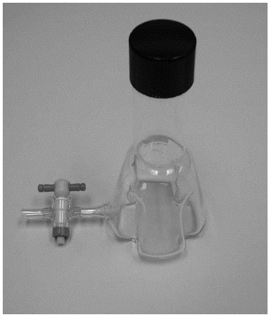
Figure 1. A Baffled Trypsinizing Flask
2.2.2 Orbital Shaker Table. An orbital shaker table with a variable speed control unit capable of maintaining 250 rpm. The orbital diameter must be approximately 1.0 inch (2.5 cm) +/−0.1 inch (0.25 cm).
2.2.3 Spectrophotometer. A UV-visible spectrophotometer capable of measuring absorbance between 340 and 400 nm ( e.g., Shimadzu UV–1800, Agilent 8453, or equivalent). Use standard transmission-matched quartz 10-mm path length rectangular cells with PTFE cover for absorbance measurements.
2.2.4 Glassware. Including: 25-ml graduated mixing cylinders (a graduated cylinder with a ground glass stopper); 50- and 100-ml graduated cylinders; 125-mL separatory funnels with Teflon stopcocks; 10-ml volumetric flasks; 30-ml crimp style glass serum bottles; 1-, 2-, 5-mL pipettes; other miscellaneous laboratory items.
2.2.5 Micropipettor. Use a micropipettor capable of dispensing 4 µL of dispersant and 100 µL of oil ( e.g., Brinkmann Eppendorf repeater pipettor with 100 µL and 5 mL syringe tip attachments or equivalent).
2.2.6 Syringes. 25-, 100-, 250-, 1,000-, 2,500-, 5,000-µl gas-tight syringes.
2.2.7 Constant temperature rooms or incubators to hold the shaker at 5 °C and 25 °C.
2.2.8 Analytical Balance.
2.2.9 Chemical fume hood.
2.3 Reagents.
2.3.1 Artificial seawater. Use the artificial seawater GP2 formulation shown in Table 1 of this Appendix.
2.3.2 Test oil. Use the EPA standard reference oil Strategic Petroleum Reserve Bryan Mound. To obtain this oil at no charge (except for a minimal shipping fee), see the instructions at http://www.epa.gov/emergencies/content/ncp/index.htm. Selected properties are summarized in Table 2 of this Appendix.
2.3.3 Dichloromethane (DCM) (also known as methylene chloride), pesticide quality.
2.4 Container Handling and Storage.
2.4.1 Glassware. If the glassware has been used with oil before, rinse with DCM to remove as much of the oil adhering to the sides of the flask as possible; waste DCM may be used. Soak in warm water with detergent and individually wash with bristled brushes. First rinse with tap water, then follow with two de-ionized water rinses. Dry either on a rack or in a 110 °C drying oven. After drying, rinse with fresh DCM (use sparingly).
2.4.2 Serum bottles and other non-volumetric glassware. Bake for at least 4 hours in a muffle furnace at 450 °C.
2.5 Calibration Curve for the UV-visible spectrophotometer.
2.5.1 Stock Standard Solution Preparation. Stock standard solution concentrations are based on the mass measurements after each addition and density determinations of the oil/dispersant/DCM solution using a density bottle or a 1-mL gas tight syringe. An example calculation is given in Table 3 of this Appendix according to the following equation:

Use the reference oil and the specific dispersant being tested for a particular set of experimental test runs. Prepare the stock standard solution of dispersant-oil mixture in DCM, starting with 2 ml of the oil, then adding 80 µl of the dispersant followed by 18 ml of DCM.
2.5.2 Six -point Calibration Curve. For the reference oil, add specific volumes of its stock standard solution (given in Table 4 of this Appendix) to 30 ml of artificial seawater in a 125 ml separatory funnel. Extract the oil/dispersant water mixture with triplicate 5 ml volumes of DCM. Follow each DCM addition by 15 seconds of vigorous shaking, carefully releasing the initial pressure inside the separatory funnel by partially removing the glass stopper inside a fume hood after the first few shakes. Then, allow a 2-minute stationary period for phase separation for each extraction. Drain the extracts into a 25-mL graduated mixing cylinder. Release any entrained bubbles of DCM from the water layer by sideways shaking of the funnel. Use precaution not to drain water into the DCM extract as it can affect the absorbance readings. Adjust the final volume of the collected extracts to 25 mL in the mixing cylinder using DCM. Determine specific masses for oil concentrations in the standards as volumes of oil/dispersant solution multiplied by the concentration of the stock solution. An example calculation is given in Table 4 of this Appendix. One calibration curve is needed for the reference oil and dispersant combination.
2.6 Sample Preparation and Testing. See section 2.7 of this Appendix for a detailed description of the spectrophotometer's linear calibration procedure.
2.6.1 Six replicates of the oil and test dispersant are required at each temperature plus two additional tests of method blanks (artificial seawater without oil and dispersant), one at each temperature. A completed test consists of 14 baffled flask tests (a total of six replicates for the reference oil/test dispersant combination at two temperatures (5 °C and 25 °C), plus two method blanks).
2.6.2 Attach a 3-inch length of Teflon tubing to the stopcock of each of the 150-mL baffled flasks. Add 120 mL of artificial seawater to each flask. Put screw cap on flasks and place them at the appropriate temperature (either 5 °C or 25 °C) for equilibration.
2.6.3 Calibrate and adjust the shaker table to 250 ± 10 rpm.
2.6.4 Prepare and time separately each baffled flask. Sequentially add 100 µL of oil and 4 µL of dispersant to the flask layering them onto the center of the seawater to give a dispersant-to-oil ratio (DOR) of 1:25. Avoid any oil or dispersant splashing on the flask walls, as it may reduce efficacy or cause errors in the calculated results. Discard the sample and repeat the setup if: (1) any oil or dispersant splashing occurs during the additions, or (2) the dispersant contacts the water first rather than the oil. This is especially important for 5 °C work because of increased oil viscosity.
2.6.5 For the oil, fill the tip of the pipettor, using a wipe to remove any oil from the sides of the tip. Holding the pipettor vertically, dispense several times back into the reservoir to ensure that the oil flows smoothly. Insert the syringe tip vertically into the baffled flask and let the bottom of the pipettor rest on the neck of the flask. Slowly and carefully dispense the oil one time onto the center of the water's surface. The remainder of the oil can either be returned to the oil bottle or set aside for use in the next test flask.
Note to 2.6.5: If a Brinkmann Eppendorf repeater pipettor is used for dispensing the oil, attach a 5-mL syringe tip, and set the dial to 1.
2.6.6 For the dispersant, use the same procedure as for the oil to dispense onto the center of the oil slick surface. As the dispersant first contacts the oil, it will usually push the oil to the sides of the flask. Replace the screw cap onto the flask.
Note to 2.6.6: If a Brinkmann Eppendorf repeater pipettor is used for dispensing the dispersant, attach a 100-µL syringe tip, and set the dial to 2.
2.6.7 Carefully place flask securely onto the shaker and agitate for 10 ± 0.25 minutes at 250 ± 10 rpm.
2.6.8 Remove the flask from the shaker table and allow a stationary, quiescent period of 10 ± 0.25 minutes to allow undispersed and/or recoalesced oil droplets to refloat to the surface.
2.6.9 Carefully open the screw cap, then the stopcock at the bottom, and discard the first several mL of seawater into a waste beaker to remove non-mixed water-oil initially trapped in the stopcock tubing. Collect a volume slightly greater than 30-mL into a 50-mL graduated cylinder. Adjust the collected volume to the 30-mL mark by removing excess with a disposable glass Pasteur pipette. A web-like emulsion may form at the solvent/water interface during the water sample extraction. Avoid pulling any emulsion phase into the DCM extract as it may cloud the DCM-extract, leading to error.
2.6.10 Transfer the water-oil sample from the graduated cylinder into a 125-mL glass separatory funnel fitted with a Teflon stopcock.
2.6.11 Add 5 mL DCM to the separatory funnel. Start shaking, releasing pressure into the fume hood by loosening the glass stopper. Shake vigorously at least 20 times for 15 seconds.
2.6.12 Allow the funnel to remain in a stationary position for 2 minutes to allow phase separation of the water and DCM.
2.6.13 Drain the DCM layer from the separatory funnel into a 25 mL mixing cylinder. Avoid pulling any emulsion phase into the DCM extract as it may cloud the DCM extract.
2.6.14 Repeat the DCM-extraction process two or three additional times until the DCM is clear. Collect each extract in the graduated cylinder. After the final extraction, lightly shake the separatory funnel sideways once or twice to dislodge entrained bubbles of DCM and drain.
2.6.15 Adjust the final volume to a known quantity, 25 mL, in the mixing cylinder. Using a syringe, dispense 2.5 mL or 5.0 mL of a reference oil sample into a 10-mL volumetric flask, and fill with DCM to make either a 1:4 or 1:2 dilution, respectively.
2.6.16 If analysis cannot be conducted immediately, store the extracted DCM samples at 4 ± 2 °C until time of analysis. Glass-stoppered mixing cylinders may be used for short-term storage or prior to bringing the extracts up to volume. After bringing to volume, transfer the DCM extracts to 25–30 ml crimp-style serum vials with aluminum/Teflon seals.
2.6.17 Complete all analysis within 10 consecutive days from when the sample was collected.
2.7 UV-Visible Spectrophotometer Linear Stability Calibration
2.7.1 A six-point calibration of the UV-visible spectrophotometer is required at least once per day for each oil. The stability calibration criterion is determined with the six oil standards identified in Table 4 of this Appendix.
2.7.2 Turn on spectrophotometer and allow it to warm up for at least 30 minutes before beginning analysis. Blank the instrument for the wavelengths between 340 and 400 nm with DCM.
2.7.3 If refrigerated, allow all extracts, standards, and samples to warm to room temperature.
2.7.4 Determine the absorbance of the six standards between the wavelengths of 340 and 400 nm. This can be done by either one of the following methods:
2.7.4.1 Trapezoidal Rule. Program the spectrophotometer to take readings every 5λ or 10λ and calculate the area under the curve using the Trapezoidal rule:
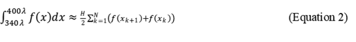
where N + 1 = number of absorbance measurements to delineate N equally spaced sections of the curve, and H = the distance (λ) between each reading. For H = 5, N + 1 = 13 measurements, for H = 10, N + 1 = 7. The following formula illustrates readings taken every 10λ.

When using readings taken every 5λ, each absorbance sum is multiplied by 5.
2.7.4.2 Automatic Integration. Program the spectrophotometer to automatically integrate the area under the curve between 340 nm and 400 nm.
2.7.4.3 If the wavelengths must be manually set on the spectrophotometer, the older method of only measuring at 340λ, 370λ, and 400λ may be used. Then calculate using the trapezoidal rule for N + 1 = 3, H = 30. While the resulting area count with the older method is less accurate, the final results are similar since the inaccuracy is systematic.
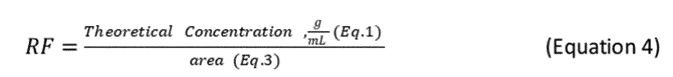
2.7.5 After determining the area count for each standard, determine the response factor (RF) for the oil at each concentration using the following equation:
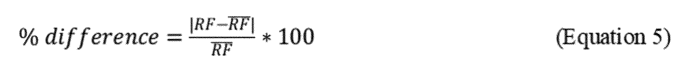
2.7.6 Spectrophotometer stability for the initial calibration is acceptable when the RFs of the six standard extracts are less than 10% different from the overall mean value for the six standards, as calculated in Equation 5 of this Appendix and depicted in the example in Table 4 of this Appendix.
2.7.7 If this criterion is satisfied, begin analysis of sample extracts. Absorbances greater than or equal to 3.5 are not included because absorbance saturation occurs at and above this value. If any of the standard oil extracts fails to satisfy the initial-stability criterion, the source of the problem ( e.g., preparation protocol for the oil standards, spectrophotometer stability, etc.) must be corrected before analysis of the sample extracts begins.
2.7.8 Determine the slope of the calibration points by using linear regression forced zero intercept:

2.8 Spectrophotometric Analysis and Calculations
2.8.1 Once a successful calibration curve for the reference oil has been created and verified, measure experimental replicates for the reference oil at each temperature followed by a standard check sample.
2.8.2 Determine the area for the absorbance values obtained for the experimental samples by using Equation 2 of this Appendix and illustrated by Equation 3 of this Appendix.
2.8.3 Calculate the Total Oil dispersed and the percentage of oil dispersed (%OD) based on the ratio of oil dispersed in the test system to the total oil added to the system, as follows:

where:
V DCM = final volume of the DCM extract (mL)
V tw = total seawater in Baffled Flask (120 mL)
V ew = volume seawater extracted (30 mL)
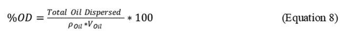
where:
r Oil = density of the specific test oil, mg/mL and
V Oil = Volume (mL of oil added to test flask (100 µL = 0.1 mL))
2.8.4 The %ODs for the six replicates within a particular treatment are then subjected to an outlier test, the Grubb's Test or Maximum Normal Residual test (6). A convenient internet-based calculator of a Grubbs outlier may be found at: http://www.graphpad.com/quickcalcs/Grubbs1.cfm. If an outlier is detected (p < 0.05), analyze an additional replicate to obtain the required six replicates.
2.8.5 Report the Dispersion Efficacy value for each oil and each temperature, which is the lower 95% confidence level of the 6 independent replicates (DE LCL95 ) for each oil/temperature combination. Error bars are not needed as reporting the lower confidence level computationally takes the variability of the replicates into account as shown in Equation 9 of this Appendix.
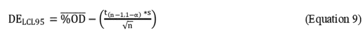
where = mean percentage oil dispersed for the n = 6 replicates, S = standard deviation, and t (n-1,1-) = 100 * (1-α)th percentile from the t-distribution with n-1 degrees of freedom. For 6 replicates, t n-1,1- = 2.015, where α = 0.05. An example of the calculations is given in Table 5 of this Appendix.
2.9 Performance Criterion
The dispersant product tested will remain in consideration for listing on the NCP Product Schedule if the dispersant efficacy (DE LCL95 ), as calculated in section 2.8.6 of this Appendix, is:
| Oil | Temp (°C) | DE LCL95 (%) |
|---|---|---|
| Bryan Mound | 5 | ≥70 |
| Bryan Mound | 25 | ≥75 |
2.10 Quality Control (QC) Procedures for Oil Concentration Measurements
2.10.1 Absorbance readings. Perform at least 5% of all UV-visible spectrophotometric measurements in duplicate as a QC check on the analytical measurement method. The absorbance values for the duplicates must agree within ±5% of their mean value.
2.10.2 Method blanks. Analytical method blanks involve an analysis of artificial seawater blanks (artificial seawater without oil or dispersant in a baffled flask) through testing and analytical procedures. Analyze method blanks with a frequency of at least two per completed test. Oil concentrations in method blanks must be less than detectable limits.
2.10.3 Accuracy. Determine accuracy by using a mid-point standard calibration check after each set of replicate samples analyzed. The acceptance criterion is based on a percent recovery of 90–110% using the following equation:

2.10.4 Calibration QC checks. Before analyzing samples, the spectrophotometer must meet an instrument stability calibration criterion using the oil standards. The instrument stability for initial calibration is acceptable when the RFs (Equation 5 of this Appendix) for each of the six standard concentration levels are less than 10% different from the overall mean value.
| Constituent | Concentration (g/L) |
|---|---|
| * Use Stock Solution, 1 mL/L GP2 for 100X stock solution for Bromide, Borate, and Strontium. 10 mL/L GP2 for bicarbonate—10X stock solution as it is not soluble in a 100X solution. Adjust to pH 8.0 prior to autoclaving. | |
| NaCl | 21.03 |
| Na 2 SO 4 | 3.52 |
| KCl | 0.61 |
| KBr * | 0.088 |
| Na 2 B 4 O 7 × 10H 2 O * | 0.034 |
| MgCl 2 × 6H 2 O | 9.50 |
| CaCl 2 × 2H 2 O | 1.32 |
| SrCl 2 × 6H 2 O * | 0.02 |
| NaHCO 2 * | 0.17 |
| Oil | Density, mg/mL @15 °C | API gravity @15 °C | Viscosity @25 °C, (cSt) | Category by API gravity |
|---|---|---|---|---|
| SPR Bryan Mound | 0.8320 | 38.6 | 4.721 | Light Oil. |
| Item | Identifier | Amount |
|---|---|---|
| Mass of Bottle, g | A | 29.498 |
| Mass of Bottle + oil, g | B | 31.225 |
| Mass of bottle + disp + oil + DCM, g | C | 54.380 |
| Mass of oil, g ( derived ) | F = B−A | 1.727 |
| Mass of disp + oil + DCM, g ( derived ) | G = C−A | 24.882 |
| Mass of 1 mL syringe, g | D | 14.556 |
| Mass of 1 mL syringe + solution, g | E | 15.820 |
| Density of solution, g/mL ( derived ) | H = E−D | 1.264 |
| Volume of solution, mL ( derived ) | I = G/H | 19.687 |
| Conc. of stock solution, mg/mL ( derived ) | J = F*1000/I | 87.704 |
| Oil + Dispersant Stock Standard Solution Concentration = 87.7 mg/mL ( Table 3 ) | ||||||
|---|---|---|---|---|---|---|
| Standard—stock vol. (uL) | Theoretical conc., mg/mL | Area (340–400 nm) | RF | Avg. RF | Dev. from avg. RF | Slope |
| 25 | 0.088 | 4.126 | 0.021 | 0.021 | 2.931 | 48.759 |
| 50 | 0.175 | 8.757 | 0.020 | 3.017 | ||
| 100 | 0.351 | 16.559 | 0.021 | 2.577 | ||
| 150 | 0.526 | 25.666 | 0.021 | 0.731 | ||
| 200 | 0.702 | 34.142 | 0.021 | 0.500 | ||
| 250 | 0.877 | 43.006 | 0.020 | 1.260 | ||
| Rep | Area (340–400 nm) | Dilution factor | Extract volume (ml) * | Conc, mg/mL. | Mass in 30 mL, mg | Total oil dispersed, mg | Efficiency, % | Average | Std. dev. | Variance | Coef. of variation | LCL95 |
|---|---|---|---|---|---|---|---|---|---|---|---|---|
| * = 25 ml of DCM extract captured oil from 30 ml of aqueous DE test. | ||||||||||||
| 1 | 32.197 | 1 | 25 | 0.66 | 16.51 | 66.03 | 79.76 | 81.30 | 4.46 | 19.85 | 5.48 | 81.30 |
| 2 | 35.470 | 1 | 25 | 0.73 | 18.19 | 72.75 | 87.87 | |||||
| 3 | 30.260 | 1 | 25 | 0.62 | 15.52 | 62.06 | 74.96 | |||||
| 4 | 31.831 | 1 | 25 | 0.65 | 16.32 | 65.28 | 78.85 | |||||
| 5 | 33.355 | 1 | 25 | 0.68 | 17.10 | 68.41 | 82.63 | |||||
| 6 | 33.791 | 1 | 25 | 0.69 | 17.33 | 69.30 | 83.71 | |||||
2.11 References for Section 2.0
(1) U.S. Environmental Protection Agency (1994), “Swirling Flask Dispersant Effectiveness Test,” Title 40 Code of Federal Regulations, Pt. 300, Appendix C, pp 47458–47461.
(2) Sorial, G.A., A.D. Venosa, K.M, Koran, E. Holder, and D.W. King. 2004. “Oil spill dispersant effectiveness protocol: I. Impact of operational variables.” ASCE J. Env. Eng. 130(10):1073–1084.
(3) Sorial, G.A., A.D. Venosa, K.M, Koran, E. Holder, and D.W. King. 2004. “Oil spill dispersant effectiveness protocol: II. Performance of revised protocol.” ASCE J. Env. Eng. 130(10):1085–1093.
(4) Venosa, A.D., D.W. King, and G.A. Sorial. 2002. “The baffled flask test for dispersant effectiveness: a round robin evaluation of reproducibility and repeatability.” Spill Sci. & Technol. Bulletin 7(5–6):299–308.
(5) Spotte, S., G. Adams, and P.M. Bubucis. 1984. “GP2 medium is an synthetic seawater for culture or maintenance of marine organisms,” Zoo Biol, 3:229–240.
(6) Grubbs, F. 1969. “Sample Criteria for Testing Outlying Observations,” Annals of Mathematical Statistics, pp. 27–58.
3.0 Dispersant Toxicity Testing
3.1 Summary. This laboratory protocol includes testing for: (1) dispersant standard static acute toxicity tests for the mysid shrimp, Americamysis bahia (48-hr duration) and the inland silverside, Menidia beryllina (96-hr duration); (2) dispersant-oil mixture static acute toxicity tests for Americamysis bahia and Menidia beryllina (48-hr and 96-hr duration, respectively); (3) dispersant developmental assay for Strongylocentrotus purpuratus or Arbacia punctulata, (72-hr duration); and (4) dispersant 7-day static subchronic tests with Americamysis bahia and Menidia beryllina (Table 6 of this Appendix).
| Test procedure | ||||
|---|---|---|---|---|
| Test substance | 96-Hr static acute: Menidia beryllina | 48-Hr static acute: AmericamysisBahia | 72-Hr sea urchin developmentalassay | 7-Day subchronic: M. beryllina &A. bahia |
| Dispersant only | yes | yes | yes | yes . |
| Dispersant—Reference Oil Mixture | yes | yes | no | no . |
3.2 Preparation of Stock Solutions
3.2.1 Dispersant. Prepare a 1000 μL/L primary stock solution prior to test initiation by adding 1.1 mL of dispersant to 1100 mL of dilution water consisting of salinity adjusted uncontaminated natural or artificial seawater, in a glass vessel. Using a laboratory top stirrer equipped with a stainless-steel blade, center the stirrer blade in the mixing vessel one inch off the bottom. Initially mix the resulting stock solution for approximately five seconds at speeds of <10,000 rpm to avoid foaming. Thereafter, set the speed to provide a 70% vortex. Using a glass pipette, remove appropriate aliquots of stock solution from between the mixing vessel wall and edge of the vortex and place directly into the dilution water within an exposure vessel. Suspend mixing of the stock solution after the removal of each aliquot. Base the preparation of exposure solutions on the nominal concentration of the stock solution and follow procedures outlined in sections 3.5 and 3.6 of this Appendix.
3.2.2 Dispersant-Reference Oil(s) Mixtures. Use Strategic Petroleum Reserve Bryan Mound reference oil. To obtain this oil at no charge (except for a minimal shipping fee) see https://www.epa.gov/emergency-response/national-contingency-plan-subpart-j#howto. Assessment of dispersant-reference oil mixture (DOM) toxicity is determined for each reference oil using the aqueous phase of a chemically enhanced-water accommodated fraction (CE–WAF). Fit a glass aspirator bottle (approximately 23 L) equipped with a hose bib at the base with a length of silicon tubing containing a hose clamp. Fill the bottle with 19L of seawater leaving a 20% headspace above the liquid, place on a magnetic stir plate then add and center a stir bar. Add the reference oil at 25 g/L using a silicon tube attached to a glass funnel that reaches just below the water surface. Using this method reduces the production of air bubbles on the oil surface slick. Adjust the stir plate to obtain an oil vortex of 25% of the total volume of the seawater, then add the dispersant to be tested at a ratio of 1:10 dispersant:oil (2.5 g/L). Securely seal the bottle to reduce the loss of volatiles using a silicon stopper and wraps of Parafilm and stir for 18 hours, then allow the solution to settle for 6 hours. Maintain the temperature at 25 °C during stirring and settling. Purge the hose at the base of the bottle of any material followed by removal of the CE–WAF (aqueous phase) into a clean glass container without disturbing the surface oil slick. The CE–WAF should be remixed and 1 to 2 L removed for chemical analysis of total petroleum hydrocarbons (TPH) following the procedures outlined in section 3.4 of this Appendix. The remaining volume will be used for the preparation of exposure solutions following procedures outlined in section 3.3 of this Appendix. To reduce time and cost, mix sufficient amounts of dispersant product-reference oil mixture CE–WAF to allow preparation of exposure solutions for conducting simultaneous acute tests with both Americamysis bahia and Menidia beryllina.
3.3 Preparation of Exposure Concentrations.
3.3.1 Concentration Selection. Preliminary rangefinder tests may be necessary using a series of logarithmic concentrations ( e.g. 0.1, 1, 10, 100 µl dispersant product/L or mg TPH/L) to determine the appropriate exposure concentration range necessary to determine LC 50 values and 95% confidence intervals. For definitive tests, conduct a minimum of five test concentrations using a geometric ratio between 1.5 and 2.0 ( e.g. 2, 4, 8, 16, and 32). Note that when testing only the dispersant product, the highest test concentration must not exceed the dispersant's self-dispersibility limit.
3.3.2 Exposure Concentrations. Exposure solutions are prepared by adding the appropriate amount of stock solution directly to dilution water in each test chamber. Mix each exposure solution using five rotations in one direction followed by five rotations in the opposite direction using a solid glass stir rod.
3.3.3 Reference Toxicants. Separate toxicity tests must be performed with a reference toxicant for each species tested. Conduct additional reference toxicity tests any time a change in the population or source of a test species occurs. Use sodium dodecyl sulfate (SDS), also known as dodecyl sodium sulfate (DSS), and sodium lauryl sulfate (SLS) as the reference toxicant for exposures conducted with Menidia beryllina and Americamysis bahia. Use copper chloride as the reference toxicant for exposures conducted with the sea urchin developmental test. Use reagent grade quality SDS and copper chloride for tests. Information on procedures for conducting reference toxicant tests with these species can be found in the specific EPA methods documents cited in sections 3.5.1, 3.6.1, and 3.7.1 of this Appendix.
3.4 Chemical Analysis of Stock Solutions. Add the 1 L sample of CE–WAF (Section 3.2.2 of this Appendix) solutions directly to amber glass bottles with Teflon®-lined cap. Collect a replicate sample in the event of accidental loss or if reanalysis of the stock solution becomes necessary. Adjust sample to a pH=2 using 50% hydrochloric acid, immediately refrigerate and analyze within 48 hours of collection. Analyze samples for C9–C32 TPH by gas chromatography-flame ionization detection (GC–FID) following EPA SW–846, Method 8015B–DRO (4). Report TPH concentration of stock solutions as milligrams TPH/L and use in the calculation of exposure concentrations for all toxicity tests conducted with CE–WAF.
3.5 Static Acute Tests with M. beryllina and A. bahia
3.5.1 General. Use EPA's Methods for Measuring the Acute Toxicity of Effluents and Receiving Waters to Freshwater and Marine Organisms (EPA–821–R–02–012) (1) for testing each species separately with dispersant product or a mixture of dispersant product and reference oil (DOM).
3.5.2 Test Solutions. Modify procedures in EPA–821–R–02–012 specifically dealing with the handling and toxicity testing of effluents or receiving water samples as follows: Prepare stock solutions following section 3.2 of this Appendix and exposure concentrations following section 3.3 of this Appendix.
3.5.3 Number of Treatments, Replicates and Organisms. Conduct a minimum of three replicates of at least five exposure treatments plus a minimum of three replicate dilution water controls. Expose ten organisms per replicate treatment.
3.5.4 Exposure Period. Test duration is 48-hr for Americamysis bahia and 96-hr for Menidia beryllina. Mortality must be recorded at each 24-hour period of each test.
3.5.5 Test Acceptability. For each test performed, survival of control animals must be >90% and test results must allow determination of statistically valid LC 50 and 95% confidence interval values except in cases where the LC 50 is >1000 μl/L or is determined to be greater than the limits of water solubility of dispersibility.
3.5.6 Static Acute Test Summary. A summary of required test conditions is provided in Table 7 of this Appendix.
3.6 Sea Urchin Developmental Test with Dispersant Product
3.6.1 General. Use Section 15, “Purple Urchin, Strongylocentrotus purpuratus and Sand Dollar, Dendraster excentricus Larval Development Test Method” of EPA's Short-Term Methods for Estimating the Chronic Toxicity of Effluents and Receiving Waters to West Coast Marine and Estuarine Organisms (EPA/600/R–95–136) (2). Alternatively, the development of the urchin Arbacia punctulata may be tested (see Table 7).
3.6.2 Test Organism. Tests of dispersant products are to follow methods for the purple urchin only. Tests with the sand dollar are not required.
3.6.3 Test Solutions. Modify procedures in EPA/600/R–95–136, Section 15 specifically dealing with the handling and toxicity testing of effluents or receiving water samples as follows: Prepare stock solutions following section 3.2.1 of this Appendix and exposure concentrations following section 3.3 of this Appendix.
3.6.4 Number of Treatments and Replicates. Conduct a minimum of four replicates of five exposure treatments plus a minimum of four replicate dilution water controls.
3.6.5 Exposure Duration and Test Endpoint. Examine the effects of the dispersant product on normal development of sea urchin embryos over a period of 72 hours. An IC 50 (the exposure concentration at which normal development is inhibited in 50% of the embryos) with 95% confidence intervals are to be determined in place of an IC 25. The concentration of dispersant causing inhibition of development in 50% of exposed embryos (IC 50 ) with the lower and upper 95% confidence intervals (LCI 95 and ULCI 95 ) must be calculated at the end of the exposure period. Mortality determinations are not required.
3.6.6 Test Acceptability. Requirements of the assay are: (i) ≥80% normal larval development in the control treatment, (ii) the minimum significant difference (MSD) that can be statically detected relative to the control is ≤25%, iii) test results which support the determination of a statistically valid IC 50 and 95% confidence interval unless the LC 50 is >1000 μl/L or is greater than the limits of water solubility of dispersibility.
3.6.7 Urchin Developmental Test Summary. A summary of required test conditions is provided in Table 7 of this Appendix.
3.7 Seven-day Subchronic Tests with M. beryllina and A. bahia
3.7.1 General. Use Section 13, Method 1006.0, “Inland Silverside ( Menidia beryllina ) Larval Survival and Growth Method,” and Section 14, Method 1007.0, “Mysid ( Mysidopsis [renamed Americamysis ] bahia ) Survival, Growth, and Fecundity Method” of EPA's Short-Term Methods for Estimating the Chronic Toxicity of Effluents and Receiving Waters to Marine and Estuarine Organisms (EPA–821–R–02–014) (3) for testing of dispersant product.
3.7.2 Test Solutions. Modify procedures in EPA–821–R–02–014, sections 13 and 14 specifically dealing with the handling and toxicity testing of effluents or receiving water samples as follows: Prepare stock solutions following section 3.2.1 of this Appendix and exposure concentrations following section 3.3 of this Appendix. Exposure solutions should be renewed every 24 hours for the duration of the test.
3.7.3 Number of Treatments, Replicates and Organisms. (i) Menidia beryllina: Conduct a minimum of four replicates of at least five exposure treatments plus a minimum of four replicate dilution water controls. Expose ten M. beryllina per replicate treatment. (ii) Americamysis bahia: Conduct a minimum of eight replicates of at least five exposure treatments plus a minimum of eight replicate dilution water controls. Expose five A. bahia per replicate treatment.
3.7.4 Exposure Duration and Test Endpoint. The test duration is seven days for both species. Test endpoints for Menidia beryllina are survival and growth (dry weight) and for Americamysis bahia is survival, growth (dry weight) and fecundity. Calculate an LC 50 and 95% confidence interval for survival and IC 25 and IC 50 with 95% confidence intervals for growth (and fecundity for A. bahia only). Report the lowest observed effect concentration (LOEC) and no observed effect concentration (NOEC) for each endpoint.
3.7.5 Test Acceptability. Requirements of the assay are: (i) ≥80% survival in the control treatment for each species, (ii) dry weights must meet the specific requirements as stipulated in Method 1006.0 for Menidia beryllina and Method 1007.0 for Americamysis bahia.
3.7.6 Subchronic Test Summary. A summary of required test conditions for each species is provided in Table 7 of this Appendix.
3.8 Laboratory Report. The laboratory must include, for each toxicity test report, all applicable information, data and analyses as follows:
3.8.1 Test Objective: protocol title and source, endpoint(s);
3.8.2 Product Information: product name, manufacturer contact information, lot number, production date, date received/chain of custody;
3.8.3 Contract Facility: contact information;
3.8.4 Dilution Water: source, pretreatment, physical and chemical characteristics (pH, salinity);
3.8.5 Test Conditions: date and time of test (start and end), test chambers type and volume, volume of solution per chamber, number of organisms per chamber, number of replicate chambers per treatment, feeding frequency, amount and type of food, test concentrations, test temperature (mean and range), test salinity (mean and range);
3.8.6 Test Organisms: common and scientific name, source contact information, age and date purchased, acclimation conditions ( e.g., temperature, salinity, both mean and range), age at test start;
3.8.7 Reference toxicant: date received, lot number, date of most recent test, results and current Cumulative Sum Chart, dilution water used, physical and chemical methods used;
3.8.8 Quality Assurance: verification of laboratory accreditation, including subcontractor facilities;
3.8.9 Test Results: raw data in tabular and graphical form, daily records of affected organisms in each concentration replicate and controls, table of required endpoints ( i.e., LC 50 with 95% confidence interval (CI), IC 25 and IC 50 with 95% CI, LOEC and NOEC), statistical methods used to calculate endpoints, summary tables of test conditions and QA data;
3.8.10 Analytical Results: method summary including Limit of Detection (LOD)/Limit of Quantitation (LOQ), deviations and reasons if any, sample summary, results including chromatograms and data qualifiers, QA summary including calibration curves, method blank and surrogate recovery, analytical results summary; and
3.8.11 Conclusions: Relationship between test endpoints and threshold limit.
| Acute M. beryllina | Acute A. bahia | Subchronic M. beryllina | Subchronic A. bahia | Development S. purpuratus/A. punctulata | |
|---|---|---|---|---|---|
| 1 Recommended minimum value. | |||||
| 2 Less than or equal to 24-hr range in age. | |||||
| Test type | Static non-renewal | Static non-renewal | Static renewal (daily) | Static renewal (daily) | Static non-renewal. |
| Test duration | 96 hours | 48 hours | 7 days | 7 days | 72 ± 2 hours. |
| Salinity | 20 ± 2‰ | 20 ± 2‰ | 20 ± 2‰ | 20 ± 2‰ | 34 ± 2‰. |
| Temperature | 25 ± 1 °C. Test temperatures must not deviate (maximum minus minimum temperature) by for than 3 °C during the test. | 15 ± 1 °C. | |||
| Light quality | Ambient laboratory illumination. 10–20 μE/m 2 /s. 16 h light, 8 h darkness, with phase in/out period recommended. | ||||
| Light intensity | |||||
| Photoperiod | |||||
| Test chamber size 1 | 250 mL | 250 mL | 600 mL–1 L | 400 mL | 30 mL. |
| Test solution volume 1 | 200 mL | 200 mL | 500–750 mL | 150 mL | 10 mL. |
| Age of test organism 2 | 9–14 days | 1–5 days | 7–11 days | 7 days | 1 hr old fertilized eggs. |
| No. organisms per test chamber | 10 | 10 | 10 | 5 | 25 embryos per mL. |
| No. of replicate chambers per concentration | 3 | 3 | 4 | 8 | 4. |
| Feeding regime | Refer to specific feeding procedures provided in each test method. | None. | |||
| Aeration | None, unless DO falls below 4.0 mg/L, then aerate all chambers. Rate: <100 bubbles/minute. 5 exposure concentrations and a control (minimum required). | ||||
| Test concentrations | |||||
| Test acceptability (required) | ≥90% survival in controls | ≥90% survival in controls | For controls: ≥80% survival; average dry weight ≥0.5mg where test starts with 7 day old larvae, or ≥0.43 mg for larvae preserved for ≤7days | For controls: ≥80% survival; average dry weight ≥0.20 mg | ≥80% normal shell development in controls. |
3.9 References for Section 3.0
(1) U.S. EPA. 2002. Methods for Measuring the Acute Toxicity of Effluents and Receiving Waters to Freshwater and Marine Organisms. Fifth Edition. U.S. Environmental Protection Agency, Washington, DC (EPA–821–R–02–012).
(2) U.S. EPA. 1995. Short-Term Methods for Estimating the Chronic Toxicity of Effluents and Receiving Waters to West Coast Marine and Estuarine Organisms. First Edition. U.S. Environmental Protection Agency, Washington, DC (EPA/600/R–95–136)
(3) U.S. EPA. 2002. Short-Term Methods for Estimating the Chronic Toxicity of Effluents and Receiving Waters to Marine and Estuarine Organisms. Third Edition. U.S. Environmental Protection Agency, Washington, DC (EPA–821–R–02–014).
(4) U.S. EPA. 2008. Test Methods for Evaluating Solid Waste, Physical/Chemical Methods U.S. Environmental Protection Agency, Washington, DC (SW–846) http://www.epa.gov/osw/hazard/testmethods/sw846/online/index.htm .
4.0 Standard Acute Toxicity Testing of Surface Washing Agents, Bioremediation Agents, Herding Agents, and Solidifiers.
4.1 Summary. This laboratory protocol includes testing for: (1) saltwater standard static acute toxicity tests for test products with the mysid shrimp, Americamysis bahia (48-hr duration) and the inland silverside, Menidia beryllina (96-hr duration); and (2) freshwater standard static acute toxicity tests for test products with the daphnid, Ceriodaphnia dubia (48-hr duration) and the fathead minnow, Pimephales promelas (96-hr duration) (see Table 8 of this Appendix).
| Application environment | Test procedure | |||
| 96-hr Static acute: Menidia beryllina | 48-hr Static acute: Americamysis bahia | 96-hr Static acute: Pimephales promelas | 48-hr Static acute: Ceriodaphnia dubia | |
| Saltwater only | yes | yes | no | no. |
| Freshwater only | no | no | yes | yes. |
| Freshwater and saltwater use | yes | yes | yes | yes. |
4.2 Dilution Water. Use Section 7 of EPA's Methods for Measuring the Acute Toxicity of Effluents and Receiving Waters to Freshwater and Marine Organisms (EPA–821–R–02–012) [1] for preparation of the appropriate dilution water for each species tested. Use of clean natural or synthetic seawater for tests conducted with saltwater species is acceptable.
4.3 Preparation of Stock Solutions.
4.3.1 Liquid Surface Washing Agents and/or Herding Agents. Prepare a 1000 µL/L stock solution prior to test initiation by adding 1.1 mL of test product to 1100 mL of dilution water in a glass vessel. Place on a magnetic stir plate then add and center a stir bar and adjust the stir plate to obtain a vortex of 25% of the total volume of the liquid. Mix the resulting stock solution for approximately five minutes at room temperature. Using a glass pipette, remove appropriate aliquots of stock solution from between the mixing vessel wall and edge of the vortex and place directly into the dilution water within an exposure vessel. Base the preparation of exposure solutions on the nominal concentration of the stock solution and follow procedures outlined in sections 4.6 and/or 4.7 of this Appendix, as appropriate.
4.3.2 Bioremediation Agents. For products consisting of two or more liquid and/or solid components, prepare the product following the manufacturers recommended procedure and ensure the test product mixture is completely blended. Prepare a 1000 µL/L stock solution prior to test initiation by adding 1.1 mL of the test product mixture to 1100 mL of dilution water in a glass vessel. Place on a magnetic stir plate then add and center a stir bar and adjust the stir plate to obtain a vortex of 25% of the total volume of the liquid. Mix the resulting stock solution for approximately five minutes at room temperature. Using a glass pipette, remove appropriate aliquots of stock solution from between the mixing vessel wall and edge of the vortex and place directly into the dilution water within an exposure vessel. Base the preparation of exposure solutions on the nominal concentration of the stock solution and follow procedures outlined in sections 4.5 and/or 4.6 of this Appendix, as appropriate.
4.3.3 Solid Phase Products. Assessment of the toxicity of solidifiers and other solid phase products are determined using the aqueous phase of water-accommodated fractions (WAFs) of the test product. Fit a glass aspirator bottle (approximately 23L) equipped with a hose bib at the base with a length of silicon tubing containing a hose clamp. Fill the bottle with 19L of dilution water leaving a 20% headspace above the liquid, place on a magnetic stir plate then add and center a stir bar. Add the test product at 25 g/L and securely seal the bottle using a silicon stopper and wraps of parafilm. Adjust the stir plate to obtain a vortex of 25% of the total fluid volume, stir for 18 hours then settle for 6 hours. Maintain the temperature at 25 °C during stirring and settling. Purge the hose at the base of the bottle of any material followed by removal of the WAF (aqueous phase) into a clean glass container without disturbing the product on the surface. The WAF should be remixed and used for the preparation of exposure solutions following procedures outlined in section 4.4 of this Appendix.
4.4 Preparation of Exposure Concentrations.
4.4.1 Concentration Selection. Preliminary rangefinder tests may be necessary using a series of logarithmic concentrations ( e.g. 0.1, 1, 10, 100 µl test product/L) to determine the appropriate exposure concentration range necessary to determine LC 50 values and 95% confidence intervals. For definitive tests, conduct a minimum of five test concentrations using a geometric ratio between 1.5 and 2.0 ( e.g. 2, 4, 8, 16, and 32). Note that when testing the product, the highest test concentration should not exceed the test product's self-dispersibility limit.
4.4.2 Exposure Concentrations. Exposure solutions are prepared by adding the appropriate amount of stock solution directly to dilution water in each test chamber. Mix each exposure solution using five rotations in one direction followed by five rotations in the opposite direction using a solid glass stir rod.
4.4.3 Reference Toxicants. Separate toxicity tests must be performed with a reference toxicant for each species tested. Conduct additional reference toxicity tests any time a change in the culture population or source of a test species occurs. Use reagent grade quality sodium dodecyl sulfate (SDS), also known as dodecyl sodium sulfate (DSS), and sodium lauryl sulfate (SLS) as the reference toxicant. Information on procedures for conducting reference toxicant tests with these species can be found in section 4 of EPA's Methods for Measuring the Acute Toxicity of Effluents and Receiving Waters to Freshwater and Marine Organisms (EPA–821–R–02–012) (3).
4.5 Saltwater Static Acute Tests with Menidia beryllina and Americamysis bahia
4.5.1 General. Use EPA's Methods for Measuring the Acute Toxicity of Effluents and Receiving Waters to Freshwater and Marine Organisms (EPA–821–R–02–012) (1) for testing each species separately with the test product.
4.5.2 Test Solutions. Modify procedures in EPA–821–R–02–012 specifically dealing with the handling and toxicity testing of effluents or receiving water samples as follows: Prepare stock solutions following the appropriate sections (4.3.1, 4.3.2, or 4.3.3) of this Appendix and exposure concentrations following section 4.4 of this Appendix.
4.5.3 Number of Treatments, Replicates and Organisms. Conduct a minimum of three replicates of at least five exposure treatments plus a minimum of three replicate dilution water controls. Expose ten organisms per replicate treatment.
4.5.4 Exposure Period. Test duration is 48-hr for A. bahia and 96-hr for M. beryllina. Mortality must be recorded at each 24 hour period of each test.
4.5.5 Test Acceptability. For each test performed, survival of control animals must be >90% and test results must allow determination of statistically valid LC 50 and 95% confidence interval values except in cases where the LC 50 is >1000 µl/L or is determined to be greater than the limits of water solubility or dispersibility.
4.5.6 Static Acute Test Summary. A summary of required test conditions is provided in Table 9 of this Appendix.
4.6 Freshwater Static Acute Tests with Pimephales promelas and Ceriodaphnia dubia
4.6.1 General. Use EPA's Methods for Measuring the Acute Toxicity of Effluents and Receiving Waters to Freshwater and Marine Organisms (EPA–821–R–02–012) (1) for testing each species separately with the test product.
4.6.2 Test Solutions. Modify procedures in EPA–821–R–02–012 specifically dealing with the handling and toxicity testing of effluents or receiving water samples as follows: Prepare stock solutions following the appropriate sections (4.3.1, 4.3.2, or 4.3.3) of this Appendix and exposure concentrations following section 4.4 of this Appendix.
4.6.3 Number of Treatments, Replicates and Organisms. P. promelas: Conduct a minimum of three replicates of at least five exposure treatments plus a minimum of three replicate dilution water controls. Expose ten organisms per replicate treatment. C. dubia: Conduct a minimum of four replicates of at least five exposure treatments plus a minimum of four replicate dilution water controls. Expose five organisms per replicate treatment.
4.6.4 Exposure Period. Test duration is 48-hr for C. dubia and 96-hr for P. promelas. Mortality must be recorded at each 24 hour period of each test.
4.6.5 Test Acceptability. For each test performed, survival of control animals must be >90% and test results must allow determination of statistically valid LC 50 and 95% confidence interval values except in cases where the LC 50 is >1000 µl/L or is determined to be greater than the limits of water solubility of dispersibility.
4.6.6 Static Acute Test Summary. A summary of required test conditions is provided in Table 9 of this Appendix.
4.7 Laboratory Report. The laboratory must include, for each toxicity test report, all applicable information, data and analyses as follows:
4.7.1 Test Objective: protocol title and source, endpoint(s);
4.7.2 Product Information: product name, manufacturer contact information, lot number, production date, date received/chain of custody;
4.7.3 Contract Facility: contact information;
4.7.4 Dilution Water: source, pretreatment, physical and chemical characteristics (pH, salinity);
4.7.5 Test Conditions: date and time of test (start and end), test chambers type and volume, volume of solution per chamber, number of organisms per chamber, number of replicate chambers per treatment, feeding frequency, amount and type of food, test concentrations, test temperature (mean and range), test salinity (mean and range);
4.7.6 Test Organisms: common and scientific name, source contact information, age and date purchased, acclimation conditions ( e.g., temperature, salinity, both mean and range), age at test start;
4.7.7 Reference toxicant: date received, lot number, date of most recent test, results and current Cumulative Sum Chart, dilution water used, physical and chemical methods used;
4.7.8 Quality Assurance: verification of laboratory accreditation, including subcontractor facilities;
4.7.9 Test Results: raw data in tabular and graphical form, daily records of affected organisms in each concentration replicate and controls, table of required endpoints ( i.e., LC 50 , 95% CI, inhibited concentration for 50% of the species (IC 50 ), lower observed effect concentration (LOEC) and no observed effect concentration (NOEC)), statistical methods used to calculate endpoints, summary tables of test conditions and QA data; and
4.7.10 Conclusions: Relationship between test endpoints and threshold limit.
| Saltwater acute M. beryllina | Saltwater acute A. bahia | Freshwater acute P. promelas | Freshwater acute C. dubia | |
|---|---|---|---|---|
| 1 Recommended minimum value. | ||||
| 2 Less than or equal to 24-hr range in age. | ||||
| Test type | Static non-renewal | Static non-renewal | Static non-renewal | Static non-renewal. |
| Test duration | 96 hours | 48 hours | 96 hours | 48 hours. |
| Salinity | 20 ± 2‰ | 20 ± 2‰ | NA | NA. |
| Temperature | 25 ± 1 °C. Test temperatures must not deviate (maximum minus minimum temperature) by more than 3 °C during the test. Ambient laboratory illumination. 10–20 µE/m 2 /s. 16 h light, 8 h darkness, with phase in/out period recommended. | |||
| Light quality | ||||
| Light intensity | ||||
| Photoperiod | ||||
| Test chamber size 1 | 250 mL | 250 mL | 250 mL | 30 mL. |
| Test solution volume 1 | 200 mL | 200 mL | 200 mL | 15 mL. |
| Age of test organism 2 | 9–14 days | 1–5 days | 1–14 days | <24 hours. |
| No. organisms per test chamber | 10 | 10 | 10 | 5. |
| No. of replicate chambers per concentration (minimum) | 3 | 3 | 3 | 4. |
| Feeding regime | Refer to specific feeding procedures provided in each test method. None, unless DO falls below 4.0 mg/L, then aerate all chambers. Rate: <100 bubbles/minute. 5 exposure concentrations and a control (minimum required). ≥90% survival in controls. | |||
| Aeration | ||||
| Test concentrations | ||||
| Test acceptability (required) | ||||
4.8 References for Section 4
(1) U.S. EPA. 2002. Methods for Measuring the Acute Toxicity of Effluents and Receiving Waters to Freshwater and Marine Organisms. Fifth Edition. U.S. Environmental Protection Agency, Washington, DC (EPA–821–R–02–012).
5.0 Bioremediation Agent Efficacy Test Protocol
5.1 Summary. This protocol quantifies changes in weathered Alaska North Slope (ANS) crude oil composition of alkanes and aromatics resulting from the use of a bioremediation agent in either artificial seawater or freshwater. The manufacturer may test either one or both freshwater or saltwater, depending on the product's intended use. Biodegradation of the alkanes and aromatics is monitored for 28 days at 20–23 °C. Product flasks at Day 28 are compared to Day 0 flasks to determine reductions in alkanes and aromatics. A positive control of a known oil-degrading bacterial consortium supplied by EPA is tested. A negative, sterile control is also set up containing exposure water, weathered crude oil, product, and a sterilant, sodium azide. The purpose of the negative, killed control is to make sure the disappearance of the oil constituents at day 28 is due to biodegradation and not some physical loss such as volatilization. The day 28 GC/MS results from the killed control must not be less than 90% of the day 0 results. The sample preparation procedure extracts the oil phase into the solvent dichloromethane (DCM) (also known as methylene chloride) with a subsequent solvent exchange into hexane. The hexane extracts are analyzed by a high-resolution gas chromatograph/mass spectrometer (GC/MS) operated in the selected ion monitoring mode (SIM) at a scan rate of >5 scans per second.
Note to 5.1: Alaska North Slope (ANS) crude oil is artificially weathered by distillation at 521 °F (272 °C) to remove the low molecular weight hydrocarbons to approximate natural weathering processes that occur after a spill.
5.2 Apparatus. All equipment must be maintained and calibrated per standard laboratory procedures.
5.2.1 Assorted flasks and other glassware;
5.2.2 Graduated cylinders (100 mL);
5.2.3 Deionized water;
5.2.4 250 mL borosilicate glass Erlenmeyer flasks;
5.2.5 250 mL separatory funnels with stopcocks
5.2.6 Pasteur pipettes;
5.2.7 Multichannel pipettor (5–50 mL and 50–200 mL);
5.2.8 Autoclave; environmental room or incubator;
5.2.9 Balance accurate to 0.1 mg;
5.2.10 Orbital shaker table with clamps sized to hold flasks securely;
5.2.11 GC/MS instrument equipped with a DB–5 capillary column (30 m, 0.25 mm ID, and 0.25 mm film thickness) or equivalent, and a split/splitless injection port operating in the splitless mode, such as an Agilent 6890 GC/5973 MS (or equivalent) equipped with an auto-sampler for testing multiple samples; and
5.2.12 Fixed Rotor Centrifuge.
5.3 Reagents and consortium medium.
5.3.1 Stock Seawater Preparation. Prepare the artificial seawater GP2 (modified from Spotte et al., 1984) following the procedures in section 2.3 of this Appendix, to obtain the final concentration of the salts listed in Table 1 of this Appendix, except for the sodium bicarbonate (NaHCO 3 ) which is prepared separately. Autoclave the artificial seawater. Filter sterilize the concentrated solution of sodium bicarbonate through a 0.45 μm membrane filter and add to the autoclaved and cooled artificial seawater GP2 to obtain the final concentration listed in Table 1 of this Appendix.
5.3.2 Seawater for the positive control flasks. Prepare sodium triphosphate (a.k.a., sodium tripolyphosphate) (Na 5 P 3 O 10 ), potassium nitrate (KNO 3 ), and ferric chloride hexahydrate (FeCl 3 · 6H 2 O) as a concentrated solution. Filter sterilize through a 0.45 μm membrane filter and add to autoclaved artificial seawater to obtain the final nutrient concentrations listed in Table 10 of this Appendix. Calibrate the pH meter at room temperature (approximately 20–23 °C) using commercial buffers of pH 4.0, 7.0, and 10.0, as appropriate, prior to use. Adjust the pH of the artificial seawater with concentrated hydrochloric acid (HCl) or 10 normality sodium hydroxide (10 N NaOH), as appropriate.
| Constituent | Final concentration, g/L |
|---|---|
| * Added aseptically after the GP2 has been autoclaved to limit phosphorus and iron precipitation. | |
| * FeCl 3 · 6H 2 O | 0.050 |
| KNO 3 | 2.890 |
| * Na 5 P 3 O 10 | 0.297 |
5.3.3 Seawater for bioremediation agents that do not include nutrients. If a bioremediation agent contains living microorganisms but not nutrients (or limiting concentrations of nutrients), then nutrients may be added by the manufacturer. However, the total concentration of the nutrients added to the bioremediation agent must not exceed the final concentrations listed in Table 11 of this Appendix.
| Constituent | Final concentration, g/L |
|---|---|
| as Iron (Fe) | 0.010 |
| as Nitrogen (N) | 0.400 |
| as Phosphorus (P) | 0.075 |
If nutrients are supplied by the product manufacturer, the specific composition and concentration used in the efficacy testing must be submitted.
5.3.4 Freshwater Preparation. The artificial freshwater, which is a modification of Bushnell-Haas medium (Haines et al., 2005), is prepared following the concentrations listed in Table 12 of this Appendix and then autoclaved. The pH is adjusted to 7.4 before autoclaving. Constituents removed from the original formulation are KNO 3 , K 2 HPO4 and KH 2 PO 4 .
| Constituent | Final concentration (mg/L) |
|---|---|
| MgSO 4 · 7H 2 O | 200 |
| CaCl 2 · 2H 2 O | 20 |
| FeCl 3 · 6H 2 O | 50 |
| MnSO 4 × H 2 O | 0.0302 |
| H 3 BO 3 | 0.0572 |
| ZnSO 4 × 7H 2 O | 0.0428 |
| (NH 4 ) 6 Mo 7 O 2 | 0.0347 |
5.3.5 Freshwater for the positive control. To prepare the freshwater for the positive controls, prepare the nutrients potassium phosphate monobasic (KH2PO4), potassium phosphate dibasic (K2HPO4) and potassium nitrate (KNO3) as a concentrated solution. Filter sterilize and add to autoclaved artificial freshwater to obtain the final concentrations given in Table 13 of this Appendix. Calibrate the pH meter at room temperature (approximately 20–23 °C) using commercial buffers of pH 4.0, 7.0, and 10.0, as appropriate, prior to use. Adjust the pH of the artificial freshwater to 7.4 with 1 N HCl or 1 N NaOH, as appropriate.
| Constituent | Final concentration (g/L) 1 |
|---|---|
| 1 Adjust pH to 7.4 prior to autoclaving. | |
| KNO 3 | 2.89 |
| KH 2 PO 4 | 1.00 |
| K 2 HPO 4 | 1.00 |
5.3.6 Freshwater for bioremediation agents that contain living microorganisms but not nutrients or limiting concentrations of nutrients. If a bioremediation agent does not include nutrients, then nutrients may be added. However, the total concentration of the nutrients added to the bioremediation agent must not exceed the final concentrations provided in Table 14 of this Appendix.
| Constituent | Final concentration, g/L 1 |
|---|---|
| 1 Adjust to pH 7.4 prior to autoclaving. | |
| as Iron (Fe) | not added since iron is already in the freshwater solution. |
| as Nitrogen (N) | 0.400. |
| as Phosphorus (P) | 0.400. |
If nutrients are supplied by the product vendor, the specific composition and concentration used in the efficacy testing must be submitted.
5.3.7 Oil Preparation. The test oil, weathered ANS521 crude oil, can be obtained from EPA at no charge (except for a minimal shipping fee). See https://www.epa.gov/emergency-response/national-contingency-plan-subpart-j#howto for more information.
5.3.8 Sodium azide sterilant. Prepare a stock solution of NaN 3 for addition to the negative killed control. The final concentration in the killed controls will be 0.5 g/L.
5.4 Experimental Setup and Procedure
5.4.1 Autoclave clean borosilicate glass Erlenmeyer flasks (250 mL) for 20 minutes at 121 °C at 15 psig.
5.4.2 Label flasks with the appropriate code (negative control, positive control, or product; day to be sampled (0 or 28); letter indicating replicate number) to reflect the following treatment design in Table 15 of this Appendix:
| * The laboratory must report positive control test results conducted within the year of any test results for bioremediation products, for one or both types of water as applicable. | |||
| Treatment | Number of replicates at sampling times | Analysis | |
| Day 0 | Day 28 | ||
| Negative (killed) Control (oil + exposure water + product + EPA consortium + NaN 3 sterilant) | 0 | 3 | GC/MS |
| * Positive control (oil + exposure water + nutrients + EPA consortium) | 6 | 6 | GC/MS |
| Test Type 1: Product containing living microorganisms (oil + exposure water + living product + supplemented nutrients (if necessary)) | 6 | 6 | GC/MS |
| Test Type 2: Product containing proprietary nutrients but no live microorganisms (oil + exposure water + product + EPA consortium) | 6 | 6 | GC/MS |
| Test Type 3: Product (such as an enzyme) containing no live microorganisms and no nutrients (oil + exposure water + product) | 6 | 6 | GC/MS |
5.4.3 Aseptically dispense 100 mL of pre-sterilized artificial exposure water (seawater or freshwater) into each sterile flask. For the positive control flasks, use exposure water containing nutrients.
5.4.4 Tare the labeled flasks containing exposure water and other additions, as necessary, on the balance with a minimum accuracy of 0.01 g. Add drop-wise 0.50 g oil (this results in a final oil concentration of 5 g/L) using a sterile Pasteur pipette to the center of the flask taking care to avoid splashing the oil onto the sides of the flasks. Record the precise weight. ANS521 may be previously warmed in a hot water bath at 60 °C for 40–60 minutes to facilitate its flow. Take precautions when handling and charging the flasks to minimize the likelihood of contamination by exogenous microbes, including using a new sterile pipette for each series of flasks.
5.4.5 Preparation of the EPA consortium for both the positive control flasks and the flasks containing non-living bio-stimulation products. Use the supplied vials containing approximately 5 mL of the known EPA consortium frozen in glycerol. Thaw the supplied vials at room temperature ( do not allow cultures preserved in glycerol to sit at room temperature past thawing ), transfer the contents of the thawed vials to a single sterile centrifuge tube, rinse tubes with two volumes each of sterile exposure water, centrifuge at between 6,000- and 7,000-times gravity (6,000–7,000 × g ) for 15 minutes using a fixed rotor to fully pellet the cells. Carefully resuspend the cell pellet in sterile exposure water using the appropriate volume to achieve the desired seeding density, which will be provided by EPA upon shipment of the consortium.
5.4.6 Positive control flasks contain exposure water, oil, nutrients, and the EPA consortium.
5.4.7 Negative killed control flasks for all products shall contain exposure water, oil, product, the EPA consortium for products not containing a living culture, and the sodium azide sterilant at a final concentration of 0.5 g/L. Add the sodium azide sterilant prior to adding any product or EPA consortium. For the negative killed control flasks and product flasks, prepare and add the product to the flasks in a concentration specified by the manufacturer or vendor.
5.4.8 For non-living products that contain nutrient only, use the EPA consortium as the inoculum.
5.4.9 For other non-living products ( e.g., enzymes), do not add nutrients or the EPA consortium as the inoculum as they are not needed.
5.4.10 For products containing living microorganisms, prepare 6 flasks the same way as in Steps a–d, but without the EPA consortium. A product that contains its own nutrients must not be amended with nutrients, unless the product contains insufficient nutrients. Since this is a closed flask test, nutrients could be limiting if they are at the same concentration as used in the field. This could cause the product to fail the test. Thus, the manufacturer has the option to supplement its product with a higher concentration of nutrients than that contained in the product. Any nutrient supplements to a product must be reported and must not exceed the concentration limits in Table 10 (for seawater) and 13 (for freshwater) of this Appendix, as applicable.
5.4.11 Cap all flasks either with sterile cotton stoppers or loosely applied aluminum foil to allow gas exchange with the atmosphere. Set aside the T = 0 flasks for immediate extraction and analysis. Place the rest of the flasks onto the orbital shaker table. Do not tip the flasks excessively to avoid stranding oil above the mixing area of the flask. Set the orbital shaker to 200 rpm and shake the flasks for 28 days at 20–23 °C in the dark.
5.4.12 Submit all information on added microorganisms and nutrients for testing in the data report.
5.5 Sampling and Chemical Analysis.
5.5.1 Summary. At each sampling event (Days 0 and 28), product and control flasks are sacrificed for analysis of residual oil concentrations (SOP 4 of this Appendix). Record all physical observations for each flask (such as degree of emulsification, whether the oil has congealed into tar balls, wall growth, color, etc.) at each sampling. The analytical procedure is summarized in Table 16 of this Appendix. Dichloromethane (DCM) is the solvent used for the initial extraction. Solvent-exchange the extract into hexane prior to injection into the gas chromatograph. The solvent exchange is done to prevent asphaltenes from contaminating the column.
| Matrix | Measurement | Sampling/ measurement method | Analysis method | Sample container/quantity of sample | Preservation/ storage (°C) | Holding times (months) |
|---|---|---|---|---|---|---|
| DCM | N/A | Solvent Exchange to Hexane | N/A | Capped Vial with Teflon septa, 30 mL | 4 | 6 |
| Hexane | Hydrocarbon Concentration | SOP 4 | GC/MS | Capped Vial with Teflon septa, 10 mL | 4 | 6 |
5.5.2 Hydrocarbon Extraction. To measure extraction efficiency, 200 µL of the 400 mg/L surrogate recovery standard (compounds and concentrations described in SOP 1 in this Appendix) is added to each flask. Add 50 mL DCM to each flask. Transfer the contents to a 250 mL separatory funnel and shake for 2 minutes; allow the phases to separate for 2 minutes. If an emulsion remains after 2 minutes, centrifuge the emulsion in Teflon® centrifuge tubes for at least ten minutes in a low-speed centrifuge at 3,000 times gravity (3,000 × g ) to break the emulsion and recover the DCM phase. Pass the DCM extract through a funnel plugged with glass wool and containing approximately 20 g anhydrous, granular sodium sulfate (Na 2 SO 4 ) to remove water. Repeat the steps above two more times with 25 mL DCM each (100 mL DCM used in total). Add 10 mL DCM on to the sodium sulfate after the third extraction to rinse off any oil residue. Collect the extract in 125 mL serum vials, capped with Teflon lined septa and aluminum crimp seals, and store at 4 °C for up to 6 months.
5.5.3 Solvent Exchange. Perform a solvent exchange (DCM to hexane) prior to GC/MS analysis to prevent injection of asphaltenes into the GC/MS column. Transfer the DCM extract to concentration tubes. Place the tubes in a 29 °C water bath under a stream of dry nitrogen gas. Reduce the sample to 1 mL and transfer the extract to a 10 mL volumetric flask. Rinse the concentration tube with hexane and add it to the volumetric flask 2 times. Adjust the final volume with hexane to 10 mL.
5.5.4 Hydrocarbon Analysis. Quantify the concentrations of 25 alkanes, 32 aromatics and hopane (SOP 4, Table SOP 4.4 of this Appendix) using an Agilent 6890 GC/5973 MS or equivalent equipped with a 30-m × 0.25-mm ID × 0.25-μm film thickness DB–5 or equivalent fused silica column. To prepare the samples, transfer 1.0 mL of the hexane extract into a 2 mL autosampler vial with Teflon lined cap. Add 20 μL of internal standard solution to each vial with a syringe or positive displacement pipettor. SOP 2 of this Appendix outlines the procedure for preparing the internal standard solution. Load vials onto the autosampler tray and analyze in selected ion monitoring mode (SIM). Sum the individual alkane concentrations for the total alkane concentration and the individual aromatic concentrations for total aromatic concentrations in each flask.
5.6 Quality Assurance/Quality Control (QA/QC).
5.6.1 Objectives. The critical variables to be analyzed for each set of experimental conditions are the individual petroleum hydrocarbons, i.e., the alkanes ranging in carbon number from nC–14 to nC–35, plus pristane and phytane, and the 2- to 4-ring polycyclic aromatic hydrocarbons (PAHs) and their alkylated homologs as listed in SOP 4 of this Appendix. The quality assurance objectives for precision, accuracy, and detection limits are ±20%, 75–125% recovery, and 22.5 µg/L on average for the 58 compounds, respectively. For more details, refer to the SOPs of this Appendix.
5.6.2 Precision Objectives. Precision is presented as relative percent difference (RPD) for duplicate measurements and as relative standard deviation (RSD, or coefficient of variance) for triplicate measurements, applicable to replication of treatments as separate samples.
5.6.3 Accuracy Objectives. These are based on the check standards and standard oil samples run concurrently with the sample analyses for GC/MS analysis of critical compounds. Critical compounds in the check standards and in the oil standards must fall within 75–125% of expected values for the analysis to be valid. Six surrogate compounds (SOP 1 of this Appendix) added to each sample before extraction can also serve as a surrogate for determining accuracy. The measured surrogate concentrations must fall within 75–125% of expected values.
5.6.4 Calibration Range. Conduct all measurements within the linear calibration range of the instrument. The calibrated concentration range for GC/MS analysis is 0.1 mg/L to 30 mg/L. If the measured concentration of any critical compound is above the calibration range, dilute the sample and re-analyze to quantify that particular compound within the linear calibration range.
5.6.5 Quality Control. Table 17 of this Appendix summarizes the QC checks for each measurement. See the corresponding SOP in this Appendix for detailed descriptions of QC checks, frequency, acceptance criteria, and corrective actions.
| Sample matrix | Measurement | QA/QC check | Frequency | Acceptance criteria | Corrective action |
|---|---|---|---|---|---|
| DCM | GC/MS hydrocarbon analysis | Blanks | Once per calibrated run | Peak area of interfering peaks <10% of lowest standard peak area | Flush with solvent, clean injection port, and/or bake column. |
| DCM | GC/MS hydrocarbon analysis | DFTPP Check Standard | Once per calibrated run | Must pass all DFTPP criteria | If any criteria fail, retune and rerun DFTPP check standard. |
| DCM | GC/MS hydrocarbon analysis | Initial Calibration Samples | Once per calibrated run | Response Factor RSD ≤25% or R2 >0.99 | If RSD for any one compound >25%, recalibrate. |
| DCM | GC/MS hydrocarbon analysis | Calibration Check Standards | Every 10–15 samples | ±25% of expected values | If >5 compounds are out of range, recalibrate and rerun samples. |
| Hexane | GC/MS hydrocarbon analysis | Surrogates | Every Sample | ±30% of expected values | Re-inject. |
| Hexane | GC/MS hydrocarbon analysis | Biomarker Concentration | Every Sample | ±25% of average values | Re-inject. |
5.7 Pass/Fail Criteria.
5.7.1 Calculate the mean and standard deviation of the hopane-normalized total aromatics (sum of all resolved aromatics) and hopane-normalized total alkane concentrations (sum of all resolved alkanes) from the 6 independent replicates at days 0 and 28. To normalize, divide the sum of the alkane analytes and the sum of the aromatic analytes in each replicate by the hopane concentration in the corresponding replicate.
5.7.2 From those data, calculate the 95% Upper Confidence Level (UCL95) at days 0 and 28 using the following formula (Equation 11 of this Appendix):
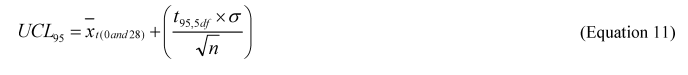
where:
x (028) = total hopane-normalized alkane or total hopane-normalized aromatic mean of 6 replicates at days 0 and 28,
t95, 5 df = the 95% one-tailed t-value with 5 degrees of freedom (2.015),
s = the standard deviation of the 6 replicates at day 0 and 28, and
n = no. of replicates = 6.
5.7.3 Using Equation 12 of this Appendix, calculate the % reduction of each oil fraction from day 0 to day 28, using the day 0 and 28 UCL 95 hopane-normalized values for each fraction:
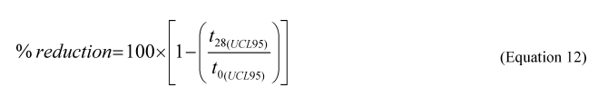
where:
t28(95) = UCL 95 of the hopane-normalized total alkane or total aromatic mean of 6 replicates on day 28, and
t0( = UCL 95 of the hopane-normalized total alkane or total aromatic mean of 6 replicates on day 0.
5.7.4 A product is successful in saltwater or freshwater if the % reduction of total alkanes (aliphatic fraction) from the GC/MS analysis is greater than or equal to 85% and the % reduction of total aromatics (aromatic fraction) is greater than or equal to 35% at day 28 based on the UCL 95 (Equation 12 of this Appendix). The benchmark reduction ranges in aliphatic and aromatic fractions for the positive control are the same as for the products specified above. The average concentration of the biomarker hopane at day 28 must not differ from the average concentration at day 0 by more than 12% in the positive control. If the conditions for the positive control are not met, the entire procedure must be repeated.
5.8 Data Verification and Reporting. GC/MS data files are generated by MS ChemStation software (the Agilent standard software for GC/MS) or equivalent for each injection. Data files contain summed ion chromatograms and selected ion chromatograms. Calibration curves are generated within MS ChemStation software, and all data files are calculated against the calibration curve by MS ChemStation. Data verification would be done by crosschecking between analysts for 10% of the raw data and its reduction process.
5.9 Laboratory Report. The summary of findings from a product test must include the data listings for each analyte that was analyzed ( i.e., all individual alkanes and aromatics in the list of required analytes), along with QA/QC checks (see Table 17) and instrument detection/reporting limits for each analyte. Express all concentrations as mg analyte/L exposure water.
5.10 Standard Operating Procedures (SOPs) 1–4
5.10.1 SOP 1. Preparation of Surrogate Recovery Standards
5.10.1.1 Preparation:
5.10.1.1.1 Solvents: Dichloromethane (DCM), Optima grade or equivalent.
5.10.1.1.2 Reagents:
D36-Heptadecane (C17)
D50-Tetracosane (C24)
D66-Dotriacontane (C32)
D10-1-Methylnaphthalene
D10-Phenanthrene
D10-Pyrene
5-beta-cholestane (coprostane)
Note: Deuterated reagents are available from Cambridge Isotope Laboratories, Andover, MA.
5.10.1.1.3 Equipment:
Micro-spatula
Small beakers
Glass funnel
Analytical balance (0.0001g)
Vials with Teflon-lined caps
Teflon wash bottle with Optima grade DCM
Volumetric flask (250 mL), class A
Pasteur pipettes
5.10.1.2 Procedure:
5.10.1.2.1 Using a calibrated analytical balance, weigh 100 mg (0.100 g) of each reagent into separate 10–25 mL beakers.
5.10.1.2.2 Dissolve the reagents in their beakers by adding 10 mL DCM. Use a Pasteur pipette to transfer the solutions to a single 250 mL volumetric flask.
5.10.1.2.3 Wash the beakers 3 or 4 times with DCM. Use a Pasteur pipette to transfer each of the washings to the 250 mL volumetric flask.
5.10.1.2.4 Dilute the solution to the 250 mL volume mark on the volumetric flask with DCM.
5.10.1.2.5 Use a glass stopper to seal the flask and homogenize the solution by inverting the flask 5 or more times. The final concentration of this solution is 400 mg/L for each of the reagents.
5.10.1.2.6 Transfer the solution into 40 mL storage vials and cap with Teflon-lined caps and label each with the date of preparation, operator, sample names, and concentrations.
5.10.1.2.7 Weigh each vial and record its weight on the label. This weight is used to monitor possible evaporation during storage.
5.10.1.2.8 Store these vials at 0 °C or lower.
5.10.1.2.9 Before using, allow the solution to come to room temperature, and then shake it well.
5.10.1.2.10 Weigh the vial before using it and compare the weight with the last weight recorded on the vial.
5.10.1.2.11 If the weights are consistent, the integrity of the solution can be assumed. If not, investigate and resolve the cause. Prepare a new solution if the integrity has been compromised.
5.10.1.3 Quality Control: Inject 20 μL of the surrogate stock solution into 1 mL DCM. Add 20 μL of the internal standard solution (SOP 2 of this Appendix). Analyze this solution by GC/MS using a calibrated method (SOPs 3 and 4 of this Appendix). The expected concentration of each of the corresponding surrogate compounds is 8 ± 2 mg/L. If the measured value does not fall within this range, prepare and measure another independent surrogate solution. If the measured concentration of the second surrogate solution is within the allowable tolerance range, the calibration and instrument conditions are acceptable; properly discard the first surrogate solution. If the concentration of the second surrogate solution is also out of range, then clean and recalibrate the instrument until the problem is resolved.
5.10.2 SOP 2. Preparation of Internal Standard Solution
5.10.2.1 Preparation:
5.10.2.1.1 Solvents: Dichloromethane (DCM), Optima grade or equivalent
5.10.2.1.2 Reagents:
D34 n-Hexadecane (C16)
D42 n-Eicosane (C20)
D62 n-Triacontane (C30)
D8-Naphthalene
D10-Anthracene
D12-Chrysene
5-alpha-Androstane
Note: Deuterated reagents are available from Cambridge Isotope Laboratories, Andover, MA.
5.10.2.1.3 Equipment:
Micro-spatula
Small beakers
Glass funnel
Analytical balance (0.0001g), calibrated and checked for accuracy
Amber vials with Teflon-lined caps, labeled
Teflon wash bottle with DCM
Volumetric flask (200 mL), class A
Pasteur pipettes
5.10.2.2 Procedure:
5.10.2.2.1 Using a calibrated analytical balance, weigh 100 mg (0.100 g) of each of the reagents into separate small beakers.
5.10.2.2.2 Dissolve the reagents in their beakers by adding 10 mL DCM; using a Pasteur pipette, transfer the solutions to a single 200 mL volumetric flask.
5.10.2.2.3 Wash the beakers 3 or 4 times with DCM; use a Pasteur pipette to transfer each of the washings to the 200 mL volume mark on the volumetric flask.
5.10.2.2.4 Dilute the solution with DCM to the 200 mL volume.
5.10.2.2.5 Seal the flask with a glass stopper and homogenize the solution by inverting the flask a minimum of 5 times. The final concentration of this solution is 500 mg/L of each reagent.
5.10.2.2.6 Transfer the solution into 40 mL storage vials and cap with Teflon-lined caps. Label each vial with the date of preparation, operator, sample names, and concentrations.
5.10.2.2.7 Weigh each vial, and record its weight on the label. This weight is used to monitor possible evaporation during storage.
5.10.2.2.8 Store this solution at 0 °C or lower.
5.10.2.2.9 Before using, allow the solution to come to room temperature, and then shake it well.
5.10.2.2.10 Weigh the vial before using it, and compare the weight with the last weight recorded on the vial.
5.10.2.2.11 If the weights are consistent, the integrity of the solution can be assumed. If not, investigate and resolve the cause. Prepare a new solution if the integrity has been compromised.
5.10.2.3 Quality Control: Inject 20 μL of the internal standard solution into 1 mL DCM. Analyze this solution by GC/MS. The only peaks corresponding to the internal standards must appear. If other peaks appear, particularly close to the internal standard peaks, discard the internal standard solution and prepare a new solution.
5.10.3 SOP 3. Preparation of Working Standards, Check Standards, and Oil Standards for GC/MS Consistency.
5.10.3.1 Preparation:
5.10.3.1.1 Solvent: Dichloromethane (DCM), Optima grade or equivalent
5.10.3.1.2 Stock solutions:
5.10.3.1.2.1 Oil analysis standard: 44 compounds, 100 mg/L in hexane/DCM (9:1), four, 1-mL vials required. Available from Absolute Standards, Inc., Hamden, CT, Part #90311.
5.10.3.1.2.2 Nine compound PAH standard: 1,000 mg/L in DCM, one vial. Available from Absolute Standards, Inc., Hamden, CT, Part #90822.
5.10.3.1.2.3 1,2-Benzodiphenylene sulfide, (synonym for naphthobenzothiophene). Prepare a 2 mg/mL stock solution. Available from Sigma-Aldrich Co., Part # 255122, purity 99%.
5.10.3.1.2.4 Hopane solution (17 α (H), 21β (H), 0.1 mg/mL in isooctane. Available from Sigma-Aldrich Co. Part #90656.
5.10.3.1.2.5 Surrogate solution: 400 mg/L of each reagent in DCM (see SOP 1 of this Appendix).
5.10.3.1.2.6 Internal standard solution, 500 mg/L in DCM (see SOP 2 of this Appendix).
5.10.3.1.3 Alaska North Slope Crude Oil 521 (ANS521).
5.10.3.1.4 Equipment:
5.10.3.1.4.1 Glass storage vials with Teflon-lined caps (2 mL and 40 mL capacity);
5.10.3.1.4.2 Volumetric flasks, Class A, 5 mL, 10 mL, and 100 mL
5.10.3.1.4.3 Glass syringes capable of dispensing 25–500 µL with an accuracy and precision of ± 1%, or equivalent
5.10.3.1.4.4 Wheaton repetitive dispenser, Model 411 STEP–PETTE or equivalent
5.10.3.1.4.5 Teflon wash bottle filled with Optima grade DCM or equivalent grade DCM
5.10.3.1.4.6 Pasteur pipettes
The volumes of stock solutions required to make the working standards are listed in Table SOP 3.1 of this Appendix.
| Stock standards | A | B | C | D | E | F | |
|---|---|---|---|---|---|---|---|
| Working standards concentration, mg/L | Oil analysis mix (44 compounds, 100 mg/L) μL | Aromatics mix (9 compounds, 1,000 mg/L) μL | 1,2-Benzo- diphenylene sulfide (NBT) (2 mg/mL) μL | Surrogate solution (100 mg/L) μL | Hopane solution (100 mg/L) μL | Volumetric flask volume mL | ISTD (500 mg/L) μL |
| * Make extra STD 5 for use as check standard. | |||||||
| STD 30 (no hopane) | 1,500 | 150 | 75 | 375 | 0 | 5 | 100 |
| STD 20 (5 mg/L hopane) | 1,000 | 100 | 50 | 250 | 250 | 5 | 100 |
| STD 10 (2.5 mg/L hopane) | 500 | 50 | 25 | 125 | 125 | 5 | 100 |
| STD 5 * (1 mg/L hopane) | 500 | 50 | 25 | 125 | 100 | 10 | 200 |
| STD 5-Utility (1 mg/L hopane) | 500 | 50 | 25 | 125 | 100 | 10 (used for preparation of STD 2.5 & STD 1) | 0 |
| STD 2.5 (0.5 mg/L hopane) | Use 5 mL of STD 5-Utility and dilute to 10 mL. Use 2 mL of STD 5-Utility and dilute to 10 mL. Use 0.2 mL of STD 5-Utility and dilute to 10 mL. | 200 | |||||
| STD 1 (0.2 mg/L hopane) | 200 | ||||||
| STD 0.1 (0.2 mg/L hopane) | 200 | ||||||
5.10.3.2 Procedure for Working Standards and Check Standards:
5.10.3.2.1 Label three 5 mL volumetric flasks as STD30, STD20, STD10, and two 10 mL volumetric flasks as STD5, and STD5-utility.
5.10.3.2.2 Add 1–2 mL of DCM to each volumetric flask.
5.10.3.2.3 Using glass syringes, add the appropriate volume of stock solution A (as listed in Table SOP 3.1 of this Appendix) to the flasks labeled STD30, STD20, STD10, STD5, and STD5-utility.
5.10.3.2.4 Wash the walls of the inner neck of the flasks with several drops of DCM to rinse off the residue of the stock solution into the flasks.
5.10.3.2.5 Repeat Step 3 and Step 4 to dispense stock solutions B–E (do not add stock solution F, internal standard solution, at this step).
5.10.3.2.6 Dilute to volume with DCM for all the above flasks, seal with glass stoppers, and invert several times to homogenize the solutions.
5.10.3.2.7 Label three additional 10 mL volumetric flasks as STD2.5, STD1, and STD0.1. Wet with 1–2 mL DCM.
5.10.3.2.8 Dispense 5 mL of STD5-utility solution into flask STD2.5, 2 mL of STD5-utility solution into flask STD1, and 0.2 mL of STD5-utility solution into flask STD0.1.
5.10.3.2.9 Dilute to volume with DCM, seal with glass stoppers, and invert several times to homogenize the solutions.
5.10.3.2.10 Using a 100 μL glass syringe, dispense 100 μL of internal standard solution into flasks STD30, STD20, and STD10. Dispense 200 μL into flasks STD5, STD2.5, STD1, and STD0.1 to give a final concentration of 10 mg/L internal standard.
5.10.3.2.11 Seal with glass stoppers, and invert the flasks several times to homogenize the solutions.
5.10.3.2.12 Transfer the solutions into 2 mL storage vials, and cap with Teflon-lined caps.
5.10.3.1.13 Label each vial with date of preparation, analyst, sample names, and concentrations.
5.10.3.2.14 Weigh each storage vial and record its weight on the label. This weight is used to monitor possible evaporation during storage.
5.10.3.2.15 Store this solution at 0 °C or below.
5.10.3.2.16 Before using, allow the solution to come to room temperature, and shake it well.
5.10.3.2.17 Weigh the vial before opening, and compare the weight with the last weight recorded on the vial. If the weights are consistent, the integrity of the solution can be assumed. If not, investigate and resolve the cause. Do not use the solution if the integrity has been compromised.
5.10.3.3 Procedure for Oil Standard. In a 100 mL volumetric flask, weigh 0.500 g of the standard ANS521 crude oil, add 2 mL of surrogate solution (see SOP 1 of this Appendix), and bring to volume with DCM. Add 2 mL of internal standard solution (see SOP 2 of this Appendix). Follow steps 5.10.3.2.11 through 5.10.3.2.17 of this SOP, substituting 40 mL storage vials for the 2 mL vials.
5.10.3.4 Quality Control/Quality Assurance:
5.10.3.4.1 Run the seven standard solutions using the GC/MS method (SOP 4) on a tuned GC/MS. Use the EnviroQuant software or equivalent to calculate the average Relative Response Factor (RRF) and the relative standard deviation (RSD) of the RRFs for each analyte over the six concentrations. The RRF is defined as:
5.10.3.4.2 The RSD of the RRFs for all analytes must be 25% or less. Alternatively, the coefficients of determination (R2) for the calibration curve for each target compounds and surrogate should be over 0.99.
5.10.4 SOP 4. GC/MS Method for the Analysis of Crude Oil Samples.
5.10.4.1 Instrument Specifications:
5.10.4.1.1 Use an Agilent 6890 GC coupled with an Agilent 5973 mass selective detector (MSD) and an Agilent 6890 series auto sampler or equivalent, equipped with a DB–5 capillary column (30 m, 0.25 mm I.D., and 0.25 μm film thickness) or equivalent, and a split/splitless injection port operating in the splitless mode. Data acquisition occurs in the SIM (selected ion monitoring) mode for quantitative analysis. In SIM mode, the dwell time of each ion is set to be 10 milliseconds and the ions are split up into groups by retention time. One way to divide the ions is by retention time grouping as shown in Table SOP 4.1 of this Appendix. The number of ions in each ion group must be constant, yielding the same scan rate for each group.
| Group | Ions |
|---|---|
| 1 | 57, 66, 128, 136, 142, 152, 156, 166, 170, 184. |
| 2 | 57, 66, 166, 170, 178, 180, 184, 188, 192, 194, 198, 208. |
| 3 | 57, 66, 178, 184, 188, 192, 194, 198, 202, 206, 208, 212, 220, 226. |
| 4 | 57, 66, 192, 198, 202, 206, 208, 212, 216, 220, 226, 230, 234, 245. |
| 5 | 57, 66, 191, 217, 228, 240, 242, 248, 256, 262, 264, 270, 276, 284. |
5.10.4.1.2 Table SOP 4.2 of this Appendix summarizes the instrumental conditions for crude oil analysis. Use only ultra-high purity helium (99.999% pure) as the carrier gas. In series, connect a moisture trap, an oxygen trap, and an organic trap to the carrier gas line before it enters the column.
| Instrument | Agilent 6890 Series II Gas Chromatograph (GC) with an Agilent 5973MSD and an Agilent 6890 auto sampler, or equivalent. |
| Column | DB–5 capillary column (30 m, 0.25 mm I.D., and 0.25-mm film thickness) or equivalent. |
| Carrier Gas | Helium, ultra-high purity grade (99.999%). |
| Inlet Temperature | 300 °C. |
| Transfer Line (detector) Temperature | 310 °C. |
| Oven Temperature Program | 50 °C for 4 minutes, then 7 °C/min to 310 °C, hold for 18 minutes. |
| Flow Rate | Constant flow at 1mL/min. Linear velocity: 36.2 cm/sec. |
| Injection Volume | 1 µL. |
| Split/Splitless Mode | Splitless. |
| Total Run Time | 59.18 minutes. |
5.10.4.2 Procedure for preparing the instrument:
5.10.4.2.1 Lower the injection port temperature and the oven temperature to 50 °C or less to avoid oxidation of the column.
5.10.4.2.2 Replace the liner with a clean, silanized liner. Do not touch the liner with bare fingers. A small piece of muffled glass wool may be inserted to protect the column.
5.10.4.2.3 Return the injection port and oven to the appropriate temperatures.
5.10.4.2.4 Wait five minutes after the temperature equilibrates before using the instrument.
5.10.4.3 Procedure for tuning the MSD:
5.10.4.3.1 Perform an air/water check. The value reported for the relative abundance of water (m/z 18), nitrogen (m/z 28), oxygen (m/z 32), or carbon dioxide (m/z 44) shall be less than 5% of the base peak for the system to be considered leak free and are expected to be closed to 1% for a stable system.
5.10.4.3.2 Tune the MSD using the Standard Autotune program and the decafluorotriphenylphosphine (DFTPP) Tune program to reduce instrument variability. The Autotune report file is referenced by the instrument when performing an air/water check and thus must be run at least once per month. Run standards and samples using DFTPP Tune parameters, and retune the instrument using DFTPP Tune at least once per week. The tune programs use three fragment ions of perfluorotributylamine (PFTBA) as a standard for tuning: m/z 69, 219, and 502. Tune reports must meet the following criteria:
5.10.4.3.2.1 Symmetrical peaks;
5.10.4.3.2.2 Mass assignments within ±0.2 amu's from 69, 219, and 502;
5.10.4.3.2.3 Peak widths within 0.5 ± 0.1 amu's;
5.10.4.3.2.4 Relative abundance is 100% for ion 69, at least 35% for ion 219, and at least 1% for ion 502;
5.10.4.3.2.5 Relative abundances for isotope masses 70, 220, and 503 ± 0.2 amu's are 0.5–1.5%, 2–8%, and 5–15%, respectively; and
5.10.4.3.2.6 Air and water peaks at m/z = 18, 28, 32, and 44 amu's must be very small and consistent with historical values.
5.10.4.4 Maintaining a log book. Maintain an instrument log book, and make entries for each use. Include the following information in the logbook: operator name, helium cylinder tank pressure and outlet pressure, vacuum gauge reading, any maintenance performed on the instrument (such as changing the injection port liner, gold seal, guard column, source cleaning), sequence name, data path, samples in order of injection, method information, GC column number, and the Standard Auto Tune report and DFTPP Tune report.
5.10.4.5 Running a Solvent Blank: Following a liner change or at the start of a new run, run an injection of a pure solvent to confirm that the system is free of excessive or interfering contamination. Analyze the solvent in SCAN mode using the same temperature program used for sample analysis. If contamination is present, analyze additional samples of fresh solvent until the interfering contamination is removed.
5.10.4.6 Checking the DFTPP Tune: Prior to running the first calibration standard, verify the instrument tune conditions by running a 10 ng/μL DFTPP check standard to check the mass measuring accuracy of the MS, the resolution sensitivity, the baseline threshold, and the ion abundance ranges. Run the standard using the DFTPP method provided with the instrument. Each of the criteria identified in Table SOP 4.2 of this Appendix must be met before using the instrument for analysis:
| Mass, M/z | Relative to mass | Relative abundance criteria | Purpose of checkpoint |
|---|---|---|---|
| 51 | 442 | 10–80% of the base peak | Low mass sensitivity. |
| 68 | 69 | <2% of mass 69 | Low mass resolution. |
| 70 | 69 | <2% of mass 69 | Low mass resolution. |
| 127 | 442 | 10–80% of the base peak | Low-mid mass sensitivity. |
| 197 | 198 | <2% of mass 198 | Mid mass resolution. |
| 198 | 442 | Base peak or >50% of 442 | Mid mass resolution and sensitivity. |
| 199 | 198 | 5–9% of mass 198 | Mid mass resolution and isotope ratio. |
| 275 | 442 | 10–60% of the base peak | Mid-high mass sensitivity. |
| 365 | 442 | >1% of the base peak | Baseline threshold. |
| 441 | 443 | Present and < mass 443 | High mass resolution. |
| 442 | 442 | Base peak or >50% of 198 | High mass resolution and sensitivity. |
| 443 | 442 | 15–24% of mass 442 | High mass resolution and isotopic ratio. |
5.10.4.7 Calibrating with a Multiple-Point Calibration Curve. A 5- or 6-point calibration curve is obtained by running 5 or 6 working standards (see SOP 3) on the tuned GC/MS instrument. Calculate the relative response factor (RRF) for each compound relative to its corresponding deuterated internal standard as indicated in Table SOP 4.3 of this Appendix. The relative standard deviation (RSD) of the RRFs for each compound must be less than 25%. Run an independently prepared check standard immediately after the calibration standards to validate the accuracy of the calibration curve.
5.10.4.8 Running Samples. Once the calibration curve has been validated, samples can be analyzed. Dispense 1,000 μL of sample extract into labeled auto-sampler vials. Add 20 μL of the internal standard solution (see SOP 2 of this Appendix) to the extract using a syringe or a positive displacement pipettor. Run a check standard every 10 samples to ensure the consistency of the instrument. The RRF for each compound in the check standard must be within 25% of the average RRF obtained in the initial calibration.
5.10.4.9 Quantification: Once a calibration table has been generated, quantify each data file using the “Calculate and Generate” function in the MS ChemStation software, or equivalent software. Review individual peak integration manually to ensure proper baseline integration. The quantification of a compound is based on the peak area of the primary ion (Q Ion) indicated in Table SOP 4.4 of this Appendix.
| Compound name | Quantitation ion | Reference compound for response factor | Internal standard for quantitation |
|---|---|---|---|
| * Summed compounds; draw an integration line underneath all peaks with selected ion. | |||
| N D34 C16 | 66 | N D34 C16 | D34 n C16 Q Ion 66. |
| n-C14 | 57 | n C14 | |
| n-C15 | 57 | n C15 | |
| n-C16 | 57 | n C16 | |
| N D34 C17 | 66 | N D34 C17 | |
| n-C17 | 57 | n C17 | |
| Pristane | 57 | Pristane | |
| n-C18 | 57 | n C18 | |
| Phytane | 57 | Phytane | |
| n C19 | 57 | n C19 | |
| N D42 C20 | 66 | N D42 C20 | D42 n C20 Q Ion 66. |
| n C20 | 57 | n C20 | |
| n C21 | 57 | n C21 | |
| n C22 | 57 | n C22 | |
| n C23 | 57 | n C23 | |
| N D50 C 24 | 66 | N D50 C 24 | |
| n C24 | 57 | n C24 | |
| n C25 | 57 | n C25 | |
| n C26 | 57 | n C26 | |
| n C27 | 57 | n C27 | |
| n C28 | 57 | n C28 | |
| n C29 | 57 | n C29 | |
| N D62 C30 | 66 | N D62 C30 | D62 n C30Q Ion 66. |
| n C30 | 57 | n C30 | |
| n C31 | 57 | n C31 | |
| N D66 C32 | 57 | N D66 C32 | |
| n C32 | 57 | n C32 | |
| n C33 | 57 | n C33 | |
| n C34 | 57 | n C34 | |
| n C35 | 57 | n C35 | |
| D8 Naphthalene | 136 | D8 Naphthalene | D8 Naphthalene Q Ion 136. |
| Naphthalene | 128 | Naphthalene | |
| D10 1-Methylnaphthalene | 152 | D10 1-Methylnaphthalene | |
| C1 Naphthalene * | 142 | C1 Naphthalene | |
| C2 Naphthalene * | 156 | C2 Naphthalene | |
| C3 Naphthalene * | 170 | C3 Naphthalene | |
| C4 Naphthalene * | 184 | C3 Naphthalene | |
| D10 Anthracene | 188 | D10 Anthracene | D10 Anthracene Q Ion 188. |
| D10 Phenanthrene | 188 | D10 Phenanthrene | |
| Phenanthrene | 178 | Phenanthrene | |
| C1 Phenanthrene * | 192 | C1 Phenanthrene | |
| C2 Phenanthrene * | 206 | C2 Phenanthrene | |
| C3 Phenanthrene * | 220 | C2 Phenanthrene | |
| C4 Phenanthrene * | 234 | C2 Phenanthrene | |
| Fluorene | 166 | Fluorene | |
| C1 Fluorene * | 180 | Fluorene | |
| C2 Fluorene * | 194 | Fluorene | |
| C3 Fluorene * | 208 | Fluorene | |
| Dibenzothiophene | 184 | Dibenzothiophene | |
| C1 Dibenzothiophene * | 198 | Dibenzothiophene | |
| C2 Dibenzothiophene * | 212 | Dibenzothiophene | |
| C3 Dibenzothiophene * | 226 | Dibenzothiophene | |
| Naphthobenzothiophene (NBT) | 234 | Naphthobenzothiophene | |
| C1 NBT * | 248 | Naphthobenzothiophene | |
| C2 NBT * | 262 | Naphthobenzothiophene | |
| C3 NBT * | 276 | Naphthobenzothiophene | |
| Fluoranthene | 202 | Fluoranthene | |
| D10 Pyrene | 212 | D10 Pyrene | |
| Pyrene | 202 | Pyrene | |
| C1 Pyrene * | 216 | Pyrene | |
| C2 Pyrene * | 230 | Pyrene | |
| D12 Chrysene | 240 | D12 Chrysene | D12 Chrysene Q Ion 240. |
| Benzo(a)anthracene/Chrysene * | 228 | Chrysene | |
| C1 Chrysene * | 242 | Chrysene | |
| C2 Chrysene * | 256 | Chrysene | |
| C3 Chrysene * | 270 | Chrysene | |
| C4 Chrysene * | 284 | Chrysene | |
| 5α-androstane | 245 | 5α-androstane | 5α-androstane Q Ion 245. |
| Coprostane | 219 | Coprostane | |
| Hopane | 191 | Hopane | |
5.10.4.10 Equation 14 of this Appendix is used to calculate the concentration of analytes in units of μg/g oil added:
where:
A analyte = the peak area of the analyte,
C istd = the concentration of the internal standard,
A istd = the area of the internal standard,
RRF = the relative response factor, and
100 is the conversion factor to convert mg/L DCM to μg/g oil added.
5.10.4.11 If some analytes are not commercially available, the RRFs of other compounds (usually the parent compound) are used to quantify those analytes. For example, the RRF of C3-naphthalene may be used to calculate the concentrations of C3- and C4-naphthalenes. See Table SOP 4.4 of this Appendix for details. The quantification of these alkylated PAHs is relative because it is assumed that the molecular ions of the alkylated PAHs have the same RRFs as the parent compound ions. Nevertheless, these relative concentrations are useful for monitoring the fate of these compounds during the course of any analysis, as long as their concentrations are measured in a consistent way throughout the analysis.
5.10.4.12 Concentration calculations for all target compounds are performed using EnviroQuant software or equivalent. Data for each sample can be printed directly using a customized report template. Data can also be automatically entered into a spreadsheet within the EnviroQuant software.
5.10.5 Quality Assurance/Quality Control. The following criteria must be met before any samples are analyzed:
5.10.5.1 Air/water check to verify the system is leak free.
5.10.5.2 AutoTune and DFTPP Tune pass all criteria.
5.10.5.3 DFTPP check standard passes all criteria.
5.10.5.4 Solvent blank scan indicates the GC/MS system is free of interfering contamination.
5.10.5.5 Prepare and monitor a control chart of a standard oil analysis. Concentrations of the analytes in the control chart must be no more than 25% different from their historical averages.
5.10.5.6 Relative response factors for analytes in the check standards inserted between every 10 samples must be no more than 25 percent different from the average RRF of those same analytes in the calibration curve. Peak shapes must be symmetrical.
5.11 References for Section 5
(1) Haines, J.R., E.J. Kleiner, K.A. McClellan, K.M. Koran, E.L. Holder, D.W. King, and A.D. Venosa. 2005. “Laboratory evaluation of oil spill bioremediation products in salt and freshwater systems.” J. Ind. Microbiol. Biotech 32: 171–185.


SUMMARY: The Environmental Protection Agency (EPA or the Agency) is amending the requirements in Subpart J of the National Oil and Hazardous Substances Pollution Contingency Plan (NCP) that govern the use of dispersants, other chemicals and other spill mitigating substances when responding to oil discharges into jurisdictional waters of the United States. This action addresses the efficacy and toxicity of dispersants and other chemical and biological agents, as well as public, state, local, and federal officials' concerns regarding their use. Specifically, the Agency is amending the Subpart J regulatory requirements for the NCP Product Schedule in two distinct ways. First, the Agency is adding new listing criteria, revising the efficacy and toxicity testing protocols, and clarifying the evaluation criteria for removing products from the NCP Product Schedule. Second, the Agency is amending requirements for the authorities, notifications, and data reporting when using chemical or biological agents in response to oil discharges to Clean Water Act (CWA) section 311 jurisdictional waters and adjoining shorelines. These requirements are anticipated to encourage the development of safer and more effective spill mitigating products and better target the use of these products to reduce the risks of oil discharges and response technologies to human health and the environment. Further, the amendments are intended to ensure that On-Scene Coordinators (OSCs), Regional Response Teams (RRTs), and Area Committees (ACs) have sufficient information to support agent authorization of use decisions.
DATES: This final rule is effective on December 11, 2023, published in the Federal Register June 12, 2023, page 38280.
View final rule.
| Subpart J—Use of Dispersants and Other Chemicals | ||
| Heading | Revised | View text |
| §300.900 General. | ||
| (a), (c) | Revised | View text |
| (d) | Added | View text |
| §300.905 NCP Product Schedule. | ||
| Entire section | Removed | View text |
| §300.910 Authorization for agent use. | ||
| Entire section | Revised | View text |
| §300.915 Data and information requirements for listing on the NCP Product Schedule or Sorbent Product List. | ||
| Entire section | Revised | View text |
| §300.920 Addition of products to Schedule. | ||
| Entire section | Removed | View text |
| §300.950 Submission of Proprietary Business Information (PBI). | ||
| Entire section | Added | View text |
| §300.955 Addition of a product to the NCP Product Schedule or Sorbent ProductLlist. | ||
| Entire section | Added | View text |
| §300.965 Mandatory Product Disclaimer. | ||
| Entire section | Added | View text |
| §300.970 Removal of a product from the NCP Product Schedule or Sorbent Product List. | ||
| Entire section | Added | View text |
| Appendix C to Part 300—Requirements for Product Testing Protocols and Summary Test Data: Dispersant Baffled Flask Efficacy and Toxicity Tests; Standard Acute Toxicity Test for Bioremediation Agents, Surface Washing Agents, Herding Agents, and Solidifiers; and Bioremediation Agent Efficacy Test | ||
| Entire appendix | Revised | View text |
| Appendix E to Part 300 | ||
| Entire appendix | Removed | View text |
New Text
§300.5 Definitions.
Subpart J—Use of Dispersants, and Other Chemical and Biological Agents
§300.900 General.
(a) Section 311(d)(2)(G) of the Clean Water Act (CWA) requires EPA to prepare a schedule identifying dispersants, other chemicals, other spill mitigating devices and substances, if any, that may be used in carrying out the NCP; and the waters and quantities in which they may be used safely. This subpart establishes a schedule that includes the NCP Product Schedule identifying chemical and biological agents, the Sorbents Product List, and the authorization of use procedures that, when taken together, identify the waters and quantities in which such dispersants, other chemicals, or other spill mitigating devices and substances may be used safely.
* * * * *
(c) This subpart applies to the use of chemical and biological agents as defined in Subpart A of this part, or other substances that may be used to remove, control, or otherwise mitigate oil discharges.
§300.910 Authorization for agent use.
Use of chemical or biological agents in response to oil discharges must be authorized by the OSC in accordance with the provisions of this section.
(a) Use of agents identified on the NCP Product Schedule or use of burning agents on oil discharges addressed by a preauthorization plan. Area Committees and RRTs shall address, as part of their planning activities, whether preauthorization of the use of chemical and biological agents listed on the NCP Product Schedule or the use of burning agents on certain oil discharges is appropriate. Area Committees and RRTs shall, as appropriate, include applicable approved preauthorization plans in ACPs and RCPs. When a preauthorization plan is approved in advance for the use of certain agents under specified discharge situations, then the OSC may authorize the use of agents listed on the NCP Product Schedule, or the use of burning agents, for the purpose for which they were specifically listed without obtaining the incident-specific concurrences and without the natural resource trustees consultations described in paragraph (b) of this section.
(1) Preauthorization plan development. For discharge situations identified where such agents may be used, the preauthorization plan must, at a minimum, specify limits for the quantities and the duration of use, and use parameters for water depth, distance to shoreline, and proximity to populated areas. In meeting the provisions of this paragraph, preauthorization plans should document how regional factors are addressed including likely sources and types of oil that might be discharged, various potential discharge scenarios, the existence and location of environmentally sensitive resources or restricted areas that might be impacted by discharged oil, and logistical factors including inventory, storage locations and manufacturing capability of available agents, availability of equipment needed for agent use, availability of adequately trained operators, and means to monitor agent use in the environment. Preauthorization plans are to be developed by the Area Committees or the RRT in consultation with the Area Committee(s).
(2) Preauthorization plan approval. The EPA representative to the RRT, the Department of Commerce and the Department of the Interior natural resource trustees and, as appropriate the RRT representative from the state(s) with jurisdiction over waters and adjoining shorelines within the preauthorization plan area shall review and either approve, approve with modification, or disapprove the preauthorization plans. The Area Committees and RRTs shall address the withdrawal of approval from a preauthorization plan, and the RRT shall notify the NRT of the status of the preauthorization plan within 30 days from any such withdrawal.
(3) Preauthorization plan reviews. The RRT in consultation with the Area Committee(s) must review, and revise, as needed, approved preauthorization plans. These reviews must be conducted following a regular timeframe, established by the RRT and documented in the plan, to address changes that may impact the conditions under which the use of chemical and biological agents have been preauthorized. Reviews must also be conducted in any affected region, at a minimum, after a major discharge or after a Spill of National Significance (SONS) relevant to the preauthorization plan area; to address revisions of the NCP Product Schedule impacting chemical or biological agents that may be individually listed within a preauthorization plan; and to reflect new listings of threatened and/or endangered species applicable to the preauthorization plan area. The EPA RRT representative, the Department of Commerce and Department of the Interior natural resource trustees, and the RRT representative from the state(s) with jurisdiction over the waters of the area to which a preauthorization plan applies shall review and either approve, approve with modification, or disapprove any revisions to the preauthorization plans.
(b) Use of agents identified on the NCP Product Schedule or use of burning agents on oil discharges not addressed by a preauthorization plan. For discharge situations that are not addressed by a preauthorization plan developed pursuant to paragraph (a) of this section, the OSC may authorize the use of chemical or biological agents identified on the NCP Product Schedule on an oil discharge, or the use of burning agents, for the specific purpose for which they were listed with the concurrence of the EPA RRT representative and, as appropriate, the concurrence of the RRT representatives from the state(s) with jurisdiction over the waters and adjoining shorelines threatened by the release or discharge, and in consultation with the Department of Commerce and Department of the Interior natural resource trustees. In meeting the provisions of this paragraph, the OSC must consider and document for their authorization request to the RRT, at a minimum, the parameters for the use of agents including the quantities requested to be authorized, the duration of use, the depth of water, the distance to shoreline and proximity to populated areas, and should consider and document factors such as environmentally sensitive resources or restricted areas that might be impacted, agent inventory and storage locations, agent manufacturing capability, availability of equipment needed for agent use, availability of adequately trained operators and appropriate means to monitor agent use in the environment.
(c) [Reserved]
(d) Temporary exception. In circumstances to prevent or substantially reduce an imminent threat to human life that cannot be immediately addressed by other procedures or provisions of the NCP, the OSC may authorize the provisional use of any chemical or biological agent, whether it is identified or not on the NCP Product Schedule, without obtaining the concurrence of the EPA RRT representative and, as appropriate, the RRT representatives from the state(s) with jurisdiction over the waters and adjoining shorelines threatened by the release or discharge, and without consultation with the Department of Commerce and the Department of the Interior natural resource trustees. This exception shall not be used as a substitute for compliance with §300.150 of this part, including the use of personal protective equipment, or when there is sufficient time to seek authorization in accordance with paragraphs (a) or (b) of this section. If an agent is authorized for use pursuant to this paragraph, the OSC shall notify as soon as possible the EPA RRT representative and as appropriate, the RRT representatives from the affected state(s) and the Department of Commerce and Department of the Interior natural resource trustees. The OSC shall document the circumstances and the reasons for use of the agent authorized pursuant to this paragraph. Agent use for individual circumstances under this exception shall be in accordance with paragraphs (a) or (b) of this section no later than 24 hours after initial application.
(e) Prohibited agents or substances. The OSC may not authorize the use of the following:
(1) Sinking agents, or any other chemical agent, biological agent, or any substance that is used to directly sink the oil to the bottom of a water body.
(2) [Reserved]
(f) Storage and use of agents listed on the NCP Product Schedule. (1) The OSC may authorize for use only products listed on the NCP Product Schedule that are documented and certified by the responsible party or its representative to have been stored under the conditions provided by the submitter under §300.915(a)(6), and whose date of use does not exceed the expiration date listed on the container's label unless otherwise specified for expired products as provided in §300.910(f)(2), at the time of the incident.
(2) The OSC may authorize for use products listed on the NCP Product Schedule that exceed their expiration date after the responsible party or its representative documents and certifies that the expired product has been stored under the conditions provided by the submitter under §300.915(a)(6) and still meets the applicable efficacy and toxicity listing provisions under §300.915, based on testing of representative samples within the previous 12 months.
(g) Supplemental testing, monitoring, and information. The RRT may require, for both planning and response, including authorization of use, supplemental toxicity and efficacy testing, or submission of available data and information that addresses site, area, and ecosystem-specific concerns relative to the use of any chemical or biological agent. The product manufacturer or responsible party shall provide, upon request of the RRT or OSC, additional monitoring or testing data and information to inform chemical or biological agent use decisions specific to a response.
(h) Recovery of chemical agents and other substances from the environment. The responsible party shall ensure that removal actions adequately contain, collect, store, and dispose of chemical agents and other substances that are to be recovered from the environment, unless otherwise directed by the OSC. Chemical agents and other substances to be recovered include solidifiers, surface washing agents, and sorbents. The OSC should, at a minimum, consider factors such as the safety of response personnel and harm to the environment in making determinations pursuant to this paragraph.
(i) Reporting of agent use. (1) The authorizing OSC shall provide the RRT the following information on chemical and biological agents used in response to an oil discharge: product name, product category, quantity and concentrations used, duration of use, location(s) of use, any available data collected, and any available analyses of efficacy and environmental effects. This information must be provided within 30 days of completion of agent use. This information may be submitted in accordance with the OSC reporting provisions under §300.165 of this part, as applicable, subject to the 30-day timing requirement.
(2) In support of sections 300.135(n) and 300.155(a) and (b) of this part, the authorizing OSC shall provide for notification to the public, updated during a response as appropriate, the following information on chemical and biological agents used in response to an oil discharge: product name, product category, quantity and concentrations used, duration of use, and location(s) of use.
§300.915 Data and information requirements for listing on the NCP Product Schedule or Sorbent Product List.
If you are submitting an application for listing a product to the NCP Product Schedule or Sorbent Product List, you must provide EPA the information required under §300.955. Technical product data submissions are not required for burning agents. Your submission for each product must contain:
(a) General information for any product category. (1) Your name, physical address, email, and telephone number;
(2) Your identity and documentation of that identity, as the manufacturer of the product, vendor, importer, distributor of the product, and/or a designated agent acting on behalf of the manufacturer.
(3) All name(s), brand(s), and/or trademark(s) under which the product is to be sold;
(4) Names, physical addresses, emails , and telephone numbers of the primary distributors, vendors, importers and/or designated agent acting on behalf of the manufacturer;
(5) The Safety Data Sheet (SDS) for the product;
(6) The maximum, minimum, and optimum temperature, humidity, and other relevant conditions for product storage and a brief description of the consequences to performance if the product is not stored within these limits;
(7) The anticipated shelf life of the product at the storage conditions noted in paragraph (a)(6) of this section and documentation for this determination;
(8) A sample product label for all name(s), brand(s), and/or trademark(s) under which the product is to be sold that includes manufacture and expiration dates, and conditions for storage. You may use an existing label provided it already contains the required dates and storage information;
(9) The chemical or biological agent category under which you want the product to be considered for listing on the NCP Product Schedule, including detailed information on the specific process(es) through which the product affects the oil, and the specific environment(s) on which it is intended to be used ( e.g., waters and/or adjoining shorelines). If your product meets the definition of more than one chemical or biological agent category, you must identify all applicable categories and provide the test data to meet the listing criteria appropriate to each;
(10) Recommended product use procedures, including product concentrations, use ratios, types of application equipment, conditions for use, any application restrictions; and, as applicable, procedures for product and oil containment, collection, recovery, and disposal. These procedures must address, as appropriate, variables such as weather, water salinity, water temperature, types and weathering states of oils or other pollutants. The procedures must include supporting documentation and current applicable standard methods used to determine them;
(11) Available information on environmental fate, including any known measured data, methodologies, and supporting documentation, on the persistence, bioconcentration factor, bioaccumulation factor, and biodegradability of the product and all of its components in the environment;
(12) The physical and chemical properties of the product, as appropriate, and a citation for the current applicable standard methods used to determine them, including:
(i) Physical state and appearance;
(ii) Vapor pressure;
(iii) Flash point;
(iv) Pour point;
(v) Viscosity;
(vi) Specific gravity;
(vii) Particle size for solid components; and
(viii) pH;
(13) The identity and concentration of all components in the product, including each specific component name; corresponding Chemical Abstract Service (CAS) Registry Number; the maximum, minimum, and average weight percent of each component in the product; and the intended function of each component ( e.g., solvent, surfactant);
(14) For products that also contain microorganisms, enzymes, and/or nutrients, provide the following along with a citation or a description of the methodology used to determine:
(i) The name of all microorganisms by current genus and species, including any reclassifications, and any physical, chemical, or biological manipulation of the genetic composition and the weight percent of each genus in the product;
(ii) The name of all enzymes and their International Union of Biochemistry (I.U.B.) number(s); Enzyme Classification (EC) code numbers; the source of each enzyme; units; and specific oil-degrading activity;
(iii) The name(s), maximum, minimum, and average weight percent of the nutrients contained in the product; and
(iv) Data, methodology, and supporting documentation, for the levels of bacterial, fungal, or viral pathogens or opportunistic pathogens including, but not limited to: enteric bacteria such as Salmonella, fecal coliforms, Shigella, coagulase positive Staphylococci, and beta hemolytic Streptococci and enterococci;
(15) Data, methodology, and supporting documentation for the levels of the following:
(i) Arsenic, cadmium, chromium, copper, lead, mercury, nickel, vanadium, zinc, and any other heavy metal reasonably expected to be in the product;
(ii) Cyanide;
(iii) Chlorinated hydrocarbons;
(iv) Pesticides;
(v) Polychlorinated Biphenyls (PCBs); and
(vi) Polycyclic aromatic hydrocarbons (PAHs).
(16) Certification, including data, methodology, and supporting documentation, indicating that the product does not contain any of the prohibited agents or substances identified in §300.910(e);
(17) Information about the accredited laboratory that conducted the required tests, including:
(i) Name of the laboratory, address, contact name, email, and phone number; and
(ii) The national and/or international accreditations held by the laboratory that are applicable to the test(s) performed;
(18) All test data and calculations, including:
(i) Raw data and replicates, including positive controls;
(ii) Notes and observations collected during tests;
(iii) Calculated mean values and standard deviations;
(iv) Reports, including a summary of stock solution preparation;
(v) Source and preparation of test organisms;
(vi) Test conditions; and
(vii) Chain of custody forms;
(19) An estimate of the annual product production volume, the average and maximum amount that could be produced per day, and the time frame needed to reach that maximum production rate in days;
(20) Recognition received from EPA's Design for the Environment (DfE) or Safer Choice programs, as applicable; and
(21) International product testing or use data or certifications, if available, informing the performance capabilities or environmental impacts of the product.
(b) Dispersant testing and listing requirements —(1) Dispersant efficacy test and listing criteria. Test the dispersant product for efficacy using the Baffled Flask Test (BFT) method in Appendix C to part 300. To be listed on the NCP Product Schedule, the dispersant must demonstrate for each temperature a Dispersant Effectiveness (DE) at the 95% lower confidence level (LCL 95 ) greater than or equal to:
(i) ≥70% for Strategic Petroleum Reserve Bryan Mound at 5 °C;
(ii) ≥75% for Strategic Petroleum Reserve Bryan Mound at 25 °C;
(2) Dispersant toxicity tests and listing criteria. Use the methods specified in Appendix C to part 300 to test the dispersant alone, and the dispersant mixed with Strategic Petroleum Reserve Bryan Mound for acute toxicity, using Americamysis bahia and Menidia beryllina. Use the methods specified in Appendix C to part 300 to test the dispersant alone for developmental toxicity using Strongylocentrotus purpuratus or Arbacia punctulata and for subchronic effects using Americamysis bahia and Menidia beryllina. To be listed on the NCP Product Schedule, the dispersant alone must demonstrate:
(i) A median lethal concentration (LC 50 ) at the lower 95% confidence interval greater than 10 ppm;
(ii) An inhibition concentration for 50% of the test species (IC 50 ) at the lower 95% confidence interval greater than 1 ppm; and
(iii) A subchronic No Observed Effect Concentration (NOEC) greater than 1 ppm.
(3) Limitations. A dispersant may only be listed on the NCP Product Schedule for use in saltwater environments for which it meets the efficacy and toxicity listing criteria.
(c) Surface washing agent testing and listing requirements —(1) Surface washing agent efficacy test and listing criteria. To be listed on the NCP Product Schedule, using an applicable standard methodology, the surface washing agent must meet an efficacy of greater than or equal to 30% in either freshwater or saltwater, or both, depending on the intended product use.
(2) Surface washing agent toxicity test and listing criteria. Using the toxicity test methodology in Appendix C to part 300, test the surface washing agent for acute toxicity against freshwater species Ceriodaphnia dubia and Pimephales promelas, or saltwater species Americamysis bahia and Menidia beryllina, or both, depending on the intended product use. To be listed on the NCP Product Schedule, the surface washing agent must demonstrate an LC 50 at the lower 95% confidence interval greater than 10 ppm in either freshwater or saltwater for all tested species.
(3) Limitations. Surface washing agent listing would be for use only in freshwater and/or saltwater environments for which it was tested and for which it met the efficacy and toxicity listing criteria.
(d) Bioremediation agent testing and listing requirements —(1) Bioremediation agent efficacy test and listing criteria. To be listed on the NCP Product Schedule, a bioremediation agent must successfully degrade both alkanes and aromatics as determined by gas chromatography/mass spectrometry (GC/MS) in freshwater or saltwater, or both, depending on the intended product use, following the test method specified in Appendix C to part 300. The percentage reduction of total alkanes (aliphatic fraction) from the GC/MS analysis must be greater than or equal to 85% at day 28, based on the ninety-fifth (95th) percentile Upper Confidence Limit (UCL 95 ) for both freshwater and saltwater. The percentage reduction of total aromatics (aromatic fraction) must be greater than or equal to 35% at day 28 for both saltwater and freshwater based on the UCL95.
(2) Bioremediation agent toxicity test and listing criteria. The bioremediation agent must be tested for acute toxicity in freshwater or saltwater, or both, depending on the intended product use, following the method specified in Appendix C to part 300. To be listed on the NCP Product Schedule, the bioremediation agent must demonstrate an LC 50 at the lower 95% confidence interval greater than 10 ppm in either freshwater or saltwater for all tested species.
(3) Limitations. Bioremediation agent listing would be for use only in the freshwater and/or saltwater environments for which it was tested and for which it met the efficacy and toxicity listing criteria.
(4) Generic listing. If the product consists solely of: ammonium nitrate, ammonium phosphate, ammonium sulfate, calcium ammonium nitrate, sodium nitrate, potassium nitrate, synthetically-derived urea, sodium triphosphate (or tripolyphosphate), sodium phosphate, potassium phosphate (mono- or dibasic), triple super phosphate, potassium sulphate, or any combination thereof, no technical product data are required. The product will be generically listed as non-proprietary nutrients on the NCP Product Schedule, and no further action is necessary.
(e) Solidifier testing and listing requirements. (1) Solidifiers must be tested for acute toxicity in freshwater or saltwater, or both, depending on the intended product use, following the method specified in Appendix C to part 300. To be listed on the NCP Product Schedule, the solidifier must demonstrate an LC 50 at the lower 95% confidence interval greater than 10 ppm in either freshwater or saltwater for all tested species.
(2) Limitations. Solidifier listing would be for use only in the freshwater and/or saltwater environments for which it was tested and for which it met the toxicity listing criteria.
(f) Herding agent testing and listing requirements. (1) Herding agents must be tested for acute toxicity in freshwater or saltwater, or both, depending on the intended product use, following the method specified in Appendix C to part 300. To be listed on the NCP Product Schedule, the herding agent must demonstrate an LC 50 at the lower 95% confidence interval greater than 10 ppm in either freshwater or saltwater for all tested species.
(2) Limitations. Herding agent listing would be for use only in freshwater and/or saltwater environments for which it was tested and for which it met the toxicity listing criteria.
(g) Sorbent requirements. Known sorbent materials and products will be identified on a publicly available Sorbent Product List for the use of such products when responding to an oil discharge as follows:
(1) For sorbent products that consist solely of the following materials, or any combination thereof, no technical data are required to be submitted for listing on the Sorbent Product List, and no further action is necessary for use as a sorbent:
(i) Feathers, cork, peat moss, and cellulose fibers such as bagasse, corncobs, and straw;
(ii) Volcanic ash, perlite, vermiculite, zeolite, and clay; and
(iii) Polypropylene, polyethylene, polyurethane, and polyester.
(2) If the product consists of one or more natural organic substances, inorganic/mineral compounds, and/or synthetic compounds not specifically identified in paragraph (g)(1) of this section but you believe the product meets the definition of a sorbent then, as applicable under §300.955(a) and (b), you must submit the following information for consideration for listing it as a sorbent on the Sorbent Product List:
(i) The information required under paragraphs (a)(1) through (a)(8), and paragraph (a)(13) through (a)(15) of this section;
(ii) The certification required under paragraph (a)(16) of this section; and
(iii) Information, including data, to support the claim your product meets the sorbent definition under §300.5.
Appendix C to Part 300—Requirements for Product Testing Protocols and Summary Test Data: Dispersant Baffled Flask Efficacy and Toxicity Tests; Standard Acute Toxicity Test for Bioremediation Agents, Surface Washing Agents, Herding Agents, and Solidifiers; and Bioremediation Agent Efficacy Test
Table of Contents
1.0 Applicability and Scope
2.0 Baffled Flask Dispersant Efficacy Test (BFT)
3.0 Dispersant Toxicity Testing
4.0 Standard Acute Toxicity Testing for Surface Washing Agents, Bioremediation Agents, Herding Agents, and Solidifiers
5.0 Bioremediation Agent Efficacy Test Protocol
Illustrations
Figure Number
1. A Baffled Trypsinizing Flask
Tables
Table Number
1. Constituent Concentrations for GP2 Artificial Seawater
2. Test Oil Characteristics
3. Stock Standard Solution Preparation
4. Dispersant Calibration Example for Test Oil
5. Sample Calculation With ANS
6. Toxicity Testing Requirements for Dispersants
7. Summary of Test Conditions—Dispersant Toxicity
8. Toxicity Testing Requirements for Surface Washing Agents, Herding Agents, Bioremediation Agents and Solidifiers
9. Summary of Test Conditions—Surface Washing Agents, Herding Agents, Bioremediation Agents and Solidifiers Toxicity
10. Artificial Seawater Nutrient Concentrations
11. Artificial Seawater Nutrient Concentrations for Bioremediation Agents Having No Nutrients Included
12. Constituent Concentrations for Artificial Freshwater (Bushnell-Haas)
13. Freshwater Nutrient Concentrations
14. Artificial Freshwater Nutrient Concentration for Bioremediation Agents Having No Nutrients Included
15. Bioremediation Efficacy Test—Summary of Experimental Setup
16. Bioremediation Efficacy—Summary of Analytical Procedures
17. QA/QC Checks
Standard Operating Procedures Tables
SOP 3–1 Amount of Stock Solutions Required To Make the Working Standards
SOP 4–1 Ions Associated With Retention Time Groups
SOP 4–2 Instrumental Conditions for Crude Oil Analysis
SOP 4–3 Ion Abundance Criteria for DFTPP
SOP 4–4 Target Compound List
1.0 Applicability and Scope. This Appendix establishes laboratory protocols required under Subpart J (Use of Dispersants and Other Chemical and Biological Agents) of 40 CFR part 300 (National Oil and Hazardous Substances Pollution Contingency Plan) to make listing determinations for the Product Schedule. The protocols apply, based on product type, to dispersants, bioremediation agents, surface washing agents, herding agents, and solidifiers as defined in Subpart A (Introduction) of 40 CFR part 300.
2.0 Baffled Flask Dispersant Efficacy Test (BFT)
2.1 Summary. This laboratory protocol establishes procedures to evaluate the degree to which a product effectively disperses oil spilled on the surface of seawater, using a modified 150-mL screw-cap trypsinizing flask (an Erlenmeyer flask with baffles) with a glass and Teflon® stopcock near the bottom to allow removal of subsurface water samples without disturbing the surface oil layer. The efficacy of a dispersant is measured using one reference oil, Strategic Petroleum Oil Reserve Bryan Mound at two temperatures (5 °C and 25 °C). Six replicates and one method blank are required at each temperature. A layer of oil is placed on the surface of artificial seawater, and the dispersant is added to the slick at a dispersant:oil ratio (DOR) of 1:25 (4%) by volume. A standard orbital shaker table provides turbulent mixing at a speed of 250 revolutions per minute (rpm) for 10 minutes, immediately after which it is maintained stationary for 10 minutes to allow non-dispersed oil to rise to the water's surface. An undisturbed water sample is removed from the bottom of the flask through the stopcock, extracted with dichloromethane (DCM), and analyzed for oil content by UV-visible absorption spectrophotometry at wavelengths ranging between 340 and 400 nm.
2.2 Apparatus. All equipment must be maintained and calibrated per standard laboratory procedures.
2.2.1 Modified Trypsinizing Flask. A modified 150 mL glass screw-capped Erlenmeyer flasks with baffles ( e.g., Wheaton No. 355394 or equivalent) fitted with a 2 mm bore Teflon® stopcock and glass tubing, the center of which is no more than 1.3 cm from the bottom, as shown in Figure 1.
Figure 1. A Baffled Trypsinizing Flask
2.2.2 Orbital Shaker Table. An orbital shaker table with a variable speed control unit capable of maintaining 250 rpm. The orbital diameter must be approximately 1.0 inch (2.5 cm) +/−0.1 inch (0.25 cm).
2.2.3 Spectrophotometer. A UV-visible spectrophotometer capable of measuring absorbance between 340 and 400 nm ( e.g., Shimadzu UV–1800, Agilent 8453, or equivalent). Use standard transmission-matched quartz 10-mm path length rectangular cells with PTFE cover for absorbance measurements.
2.2.4 Glassware. Including: 25-ml graduated mixing cylinders (a graduated cylinder with a ground glass stopper); 50- and 100-ml graduated cylinders; 125-mL separatory funnels with Teflon stopcocks; 10-ml volumetric flasks; 30-ml crimp style glass serum bottles; 1-, 2-, 5-mL pipettes; other miscellaneous laboratory items.
2.2.5 Micropipettor. Use a micropipettor capable of dispensing 4 µL of dispersant and 100 µL of oil ( e.g., Brinkmann Eppendorf repeater pipettor with 100 µL and 5 mL syringe tip attachments or equivalent).
2.2.6 Syringes. 25-, 100-, 250-, 1,000-, 2,500-, 5,000-µl gas-tight syringes.
2.2.7 Constant temperature rooms or incubators to hold the shaker at 5 °C and 25 °C.
2.2.8 Analytical Balance.
2.2.9 Chemical fume hood.
2.3 Reagents.
2.3.1 Artificial seawater. Use the artificial seawater GP2 formulation shown in Table 1 of this Appendix.
2.3.2 Test oil. Use the EPA standard reference oil Strategic Petroleum Reserve Bryan Mound. To obtain this oil at no charge (except for a minimal shipping fee), see the instructions at http://www.epa.gov/emergencies/content/ncp/index.htm. Selected properties are summarized in Table 2 of this Appendix.
2.3.3 Dichloromethane (DCM) (also known as methylene chloride), pesticide quality.
2.4 Container Handling and Storage.
2.4.1 Glassware. If the glassware has been used with oil before, rinse with DCM to remove as much of the oil adhering to the sides of the flask as possible; waste DCM may be used. Soak in warm water with detergent and individually wash with bristled brushes. First rinse with tap water, then follow with two de-ionized water rinses. Dry either on a rack or in a 110 °C drying oven. After drying, rinse with fresh DCM (use sparingly).
2.4.2 Serum bottles and other non-volumetric glassware. Bake for at least 4 hours in a muffle furnace at 450 °C.
2.5 Calibration Curve for the UV-visible spectrophotometer.
2.5.1 Stock Standard Solution Preparation. Stock standard solution concentrations are based on the mass measurements after each addition and density determinations of the oil/dispersant/DCM solution using a density bottle or a 1-mL gas tight syringe. An example calculation is given in Table 3 of this Appendix according to the following equation:
Use the reference oil and the specific dispersant being tested for a particular set of experimental test runs. Prepare the stock standard solution of dispersant-oil mixture in DCM, starting with 2 ml of the oil, then adding 80 µl of the dispersant followed by 18 ml of DCM.
2.5.2 Six -point Calibration Curve. For the reference oil, add specific volumes of its stock standard solution (given in Table 4 of this Appendix) to 30 ml of artificial seawater in a 125 ml separatory funnel. Extract the oil/dispersant water mixture with triplicate 5 ml volumes of DCM. Follow each DCM addition by 15 seconds of vigorous shaking, carefully releasing the initial pressure inside the separatory funnel by partially removing the glass stopper inside a fume hood after the first few shakes. Then, allow a 2-minute stationary period for phase separation for each extraction. Drain the extracts into a 25-mL graduated mixing cylinder. Release any entrained bubbles of DCM from the water layer by sideways shaking of the funnel. Use precaution not to drain water into the DCM extract as it can affect the absorbance readings. Adjust the final volume of the collected extracts to 25 mL in the mixing cylinder using DCM. Determine specific masses for oil concentrations in the standards as volumes of oil/dispersant solution multiplied by the concentration of the stock solution. An example calculation is given in Table 4 of this Appendix. One calibration curve is needed for the reference oil and dispersant combination.
2.6 Sample Preparation and Testing. See section 2.7 of this Appendix for a detailed description of the spectrophotometer's linear calibration procedure.
2.6.1 Six replicates of the oil and test dispersant are required at each temperature plus two additional tests of method blanks (artificial seawater without oil and dispersant), one at each temperature. A completed test consists of 14 baffled flask tests (a total of six replicates for the reference oil/test dispersant combination at two temperatures (5 °C and 25 °C), plus two method blanks).
2.6.2 Attach a 3-inch length of Teflon tubing to the stopcock of each of the 150-mL baffled flasks. Add 120 mL of artificial seawater to each flask. Put screw cap on flasks and place them at the appropriate temperature (either 5 °C or 25 °C) for equilibration.
2.6.3 Calibrate and adjust the shaker table to 250 ± 10 rpm.
2.6.4 Prepare and time separately each baffled flask. Sequentially add 100 µL of oil and 4 µL of dispersant to the flask layering them onto the center of the seawater to give a dispersant-to-oil ratio (DOR) of 1:25. Avoid any oil or dispersant splashing on the flask walls, as it may reduce efficacy or cause errors in the calculated results. Discard the sample and repeat the setup if: (1) any oil or dispersant splashing occurs during the additions, or (2) the dispersant contacts the water first rather than the oil. This is especially important for 5 °C work because of increased oil viscosity.
2.6.5 For the oil, fill the tip of the pipettor, using a wipe to remove any oil from the sides of the tip. Holding the pipettor vertically, dispense several times back into the reservoir to ensure that the oil flows smoothly. Insert the syringe tip vertically into the baffled flask and let the bottom of the pipettor rest on the neck of the flask. Slowly and carefully dispense the oil one time onto the center of the water's surface. The remainder of the oil can either be returned to the oil bottle or set aside for use in the next test flask.
Note to 2.6.5: If a Brinkmann Eppendorf repeater pipettor is used for dispensing the oil, attach a 5-mL syringe tip, and set the dial to 1.
2.6.6 For the dispersant, use the same procedure as for the oil to dispense onto the center of the oil slick surface. As the dispersant first contacts the oil, it will usually push the oil to the sides of the flask. Replace the screw cap onto the flask.
Note to 2.6.6: If a Brinkmann Eppendorf repeater pipettor is used for dispensing the dispersant, attach a 100-µL syringe tip, and set the dial to 2.
2.6.7 Carefully place flask securely onto the shaker and agitate for 10 ± 0.25 minutes at 250 ± 10 rpm.
2.6.8 Remove the flask from the shaker table and allow a stationary, quiescent period of 10 ± 0.25 minutes to allow undispersed and/or recoalesced oil droplets to refloat to the surface.
2.6.9 Carefully open the screw cap, then the stopcock at the bottom, and discard the first several mL of seawater into a waste beaker to remove non-mixed water-oil initially trapped in the stopcock tubing. Collect a volume slightly greater than 30-mL into a 50-mL graduated cylinder. Adjust the collected volume to the 30-mL mark by removing excess with a disposable glass Pasteur pipette. A web-like emulsion may form at the solvent/water interface during the water sample extraction. Avoid pulling any emulsion phase into the DCM extract as it may cloud the DCM-extract, leading to error.
2.6.10 Transfer the water-oil sample from the graduated cylinder into a 125-mL glass separatory funnel fitted with a Teflon stopcock.
2.6.11 Add 5 mL DCM to the separatory funnel. Start shaking, releasing pressure into the fume hood by loosening the glass stopper. Shake vigorously at least 20 times for 15 seconds.
2.6.12 Allow the funnel to remain in a stationary position for 2 minutes to allow phase separation of the water and DCM.
2.6.13 Drain the DCM layer from the separatory funnel into a 25 mL mixing cylinder. Avoid pulling any emulsion phase into the DCM extract as it may cloud the DCM extract.
2.6.14 Repeat the DCM-extraction process two or three additional times until the DCM is clear. Collect each extract in the graduated cylinder. After the final extraction, lightly shake the separatory funnel sideways once or twice to dislodge entrained bubbles of DCM and drain.
2.6.15 Adjust the final volume to a known quantity, 25 mL, in the mixing cylinder. Using a syringe, dispense 2.5 mL or 5.0 mL of a reference oil sample into a 10-mL volumetric flask, and fill with DCM to make either a 1:4 or 1:2 dilution, respectively.
2.6.16 If analysis cannot be conducted immediately, store the extracted DCM samples at 4 ± 2 °C until time of analysis. Glass-stoppered mixing cylinders may be used for short-term storage or prior to bringing the extracts up to volume. After bringing to volume, transfer the DCM extracts to 25–30 ml crimp-style serum vials with aluminum/Teflon seals.
2.6.17 Complete all analysis within 10 consecutive days from when the sample was collected.
2.7 UV-Visible Spectrophotometer Linear Stability Calibration
2.7.1 A six-point calibration of the UV-visible spectrophotometer is required at least once per day for each oil. The stability calibration criterion is determined with the six oil standards identified in Table 4 of this Appendix.
2.7.2 Turn on spectrophotometer and allow it to warm up for at least 30 minutes before beginning analysis. Blank the instrument for the wavelengths between 340 and 400 nm with DCM.
2.7.3 If refrigerated, allow all extracts, standards, and samples to warm to room temperature.
2.7.4 Determine the absorbance of the six standards between the wavelengths of 340 and 400 nm. This can be done by either one of the following methods:
2.7.4.1 Trapezoidal Rule. Program the spectrophotometer to take readings every 5λ or 10λ and calculate the area under the curve using the Trapezoidal rule:
where N + 1 = number of absorbance measurements to delineate N equally spaced sections of the curve, and H = the distance (λ) between each reading. For H = 5, N + 1 = 13 measurements, for H = 10, N + 1 = 7. The following formula illustrates readings taken every 10λ.
When using readings taken every 5λ, each absorbance sum is multiplied by 5.
2.7.4.2 Automatic Integration. Program the spectrophotometer to automatically integrate the area under the curve between 340 nm and 400 nm.
2.7.4.3 If the wavelengths must be manually set on the spectrophotometer, the older method of only measuring at 340λ, 370λ, and 400λ may be used. Then calculate using the trapezoidal rule for N + 1 = 3, H = 30. While the resulting area count with the older method is less accurate, the final results are similar since the inaccuracy is systematic.
2.7.5 After determining the area count for each standard, determine the response factor (RF) for the oil at each concentration using the following equation:
2.7.6 Spectrophotometer stability for the initial calibration is acceptable when the RFs of the six standard extracts are less than 10% different from the overall mean value for the six standards, as calculated in Equation 5 of this Appendix and depicted in the example in Table 4 of this Appendix.
2.7.7 If this criterion is satisfied, begin analysis of sample extracts. Absorbances greater than or equal to 3.5 are not included because absorbance saturation occurs at and above this value. If any of the standard oil extracts fails to satisfy the initial-stability criterion, the source of the problem ( e.g., preparation protocol for the oil standards, spectrophotometer stability, etc.) must be corrected before analysis of the sample extracts begins.
2.7.8 Determine the slope of the calibration points by using linear regression forced zero intercept:
2.8 Spectrophotometric Analysis and Calculations
2.8.1 Once a successful calibration curve for the reference oil has been created and verified, measure experimental replicates for the reference oil at each temperature followed by a standard check sample.
2.8.2 Determine the area for the absorbance values obtained for the experimental samples by using Equation 2 of this Appendix and illustrated by Equation 3 of this Appendix.
2.8.3 Calculate the Total Oil dispersed and the percentage of oil dispersed (%OD) based on the ratio of oil dispersed in the test system to the total oil added to the system, as follows:
where:
V DCM = final volume of the DCM extract (mL)
V tw = total seawater in Baffled Flask (120 mL)
V ew = volume seawater extracted (30 mL)
where:
r Oil = density of the specific test oil, mg/mL and
V Oil = Volume (mL of oil added to test flask (100 µL = 0.1 mL))
2.8.4 The %ODs for the six replicates within a particular treatment are then subjected to an outlier test, the Grubb's Test or Maximum Normal Residual test (6). A convenient internet-based calculator of a Grubbs outlier may be found at: http://www.graphpad.com/quickcalcs/Grubbs1.cfm. If an outlier is detected (p < 0.05), analyze an additional replicate to obtain the required six replicates.
2.8.5 Report the Dispersion Efficacy value for each oil and each temperature, which is the lower 95% confidence level of the 6 independent replicates (DE LCL95 ) for each oil/temperature combination. Error bars are not needed as reporting the lower confidence level computationally takes the variability of the replicates into account as shown in Equation 9 of this Appendix.
where = mean percentage oil dispersed for the n = 6 replicates, S = standard deviation, and t (n-1,1-) = 100 * (1-α)th percentile from the t-distribution with n-1 degrees of freedom. For 6 replicates, t n-1,1- = 2.015, where α = 0.05. An example of the calculations is given in Table 5 of this Appendix.
2.9 Performance Criterion
The dispersant product tested will remain in consideration for listing on the NCP Product Schedule if the dispersant efficacy (DE LCL95 ), as calculated in section 2.8.6 of this Appendix, is:
| Oil | Temp (°C) | DE LCL95 (%) |
|---|---|---|
| Bryan Mound | 5 | ≥70 |
| Bryan Mound | 25 | ≥75 |
2.10 Quality Control (QC) Procedures for Oil Concentration Measurements
2.10.1 Absorbance readings. Perform at least 5% of all UV-visible spectrophotometric measurements in duplicate as a QC check on the analytical measurement method. The absorbance values for the duplicates must agree within ±5% of their mean value.
2.10.2 Method blanks. Analytical method blanks involve an analysis of artificial seawater blanks (artificial seawater without oil or dispersant in a baffled flask) through testing and analytical procedures. Analyze method blanks with a frequency of at least two per completed test. Oil concentrations in method blanks must be less than detectable limits.
2.10.3 Accuracy. Determine accuracy by using a mid-point standard calibration check after each set of replicate samples analyzed. The acceptance criterion is based on a percent recovery of 90–110% using the following equation:
2.10.4 Calibration QC checks. Before analyzing samples, the spectrophotometer must meet an instrument stability calibration criterion using the oil standards. The instrument stability for initial calibration is acceptable when the RFs (Equation 5 of this Appendix) for each of the six standard concentration levels are less than 10% different from the overall mean value.
| Constituent | Concentration (g/L) |
|---|---|
| * Use Stock Solution, 1 mL/L GP2 for 100X stock solution for Bromide, Borate, and Strontium. 10 mL/L GP2 for bicarbonate—10X stock solution as it is not soluble in a 100X solution. Adjust to pH 8.0 prior to autoclaving. | |
| NaCl | 21.03 |
| Na 2 SO 4 | 3.52 |
| KCl | 0.61 |
| KBr * | 0.088 |
| Na 2 B 4 O 7 × 10H 2 O * | 0.034 |
| MgCl 2 × 6H 2 O | 9.50 |
| CaCl 2 × 2H 2 O | 1.32 |
| SrCl 2 × 6H 2 O * | 0.02 |
| NaHCO 2 * | 0.17 |
| Oil | Density, mg/mL @15 °C | API gravity @15 °C | Viscosity @25 °C, (cSt) | Category by API gravity |
|---|---|---|---|---|
| SPR Bryan Mound | 0.8320 | 38.6 | 4.721 | Light Oil. |
| Item | Identifier | Amount |
|---|---|---|
| Mass of Bottle, g | A | 29.498 |
| Mass of Bottle + oil, g | B | 31.225 |
| Mass of bottle + disp + oil + DCM, g | C | 54.380 |
| Mass of oil, g ( derived ) | F = B−A | 1.727 |
| Mass of disp + oil + DCM, g ( derived ) | G = C−A | 24.882 |
| Mass of 1 mL syringe, g | D | 14.556 |
| Mass of 1 mL syringe + solution, g | E | 15.820 |
| Density of solution, g/mL ( derived ) | H = E−D | 1.264 |
| Volume of solution, mL ( derived ) | I = G/H | 19.687 |
| Conc. of stock solution, mg/mL ( derived ) | J = F*1000/I | 87.704 |
| Oil + Dispersant Stock Standard Solution Concentration = 87.7 mg/mL ( Table 3 ) | ||||||
|---|---|---|---|---|---|---|
| Standard—stock vol. (uL) | Theoretical conc., mg/mL | Area (340–400 nm) | RF | Avg. RF | Dev. from avg. RF | Slope |
| 25 | 0.088 | 4.126 | 0.021 | 0.021 | 2.931 | 48.759 |
| 50 | 0.175 | 8.757 | 0.020 | 3.017 | ||
| 100 | 0.351 | 16.559 | 0.021 | 2.577 | ||
| 150 | 0.526 | 25.666 | 0.021 | 0.731 | ||
| 200 | 0.702 | 34.142 | 0.021 | 0.500 | ||
| 250 | 0.877 | 43.006 | 0.020 | 1.260 | ||
| Rep | Area (340–400 nm) | Dilution factor | Extract volume (ml) * | Conc, mg/mL. | Mass in 30 mL, mg | Total oil dispersed, mg | Efficiency, % | Average | Std. dev. | Variance | Coef. of variation | LCL95 |
|---|---|---|---|---|---|---|---|---|---|---|---|---|
| * = 25 ml of DCM extract captured oil from 30 ml of aqueous DE test. | ||||||||||||
| 1 | 32.197 | 1 | 25 | 0.66 | 16.51 | 66.03 | 79.76 | 81.30 | 4.46 | 19.85 | 5.48 | 81.30 |
| 2 | 35.470 | 1 | 25 | 0.73 | 18.19 | 72.75 | 87.87 | |||||
| 3 | 30.260 | 1 | 25 | 0.62 | 15.52 | 62.06 | 74.96 | |||||
| 4 | 31.831 | 1 | 25 | 0.65 | 16.32 | 65.28 | 78.85 | |||||
| 5 | 33.355 | 1 | 25 | 0.68 | 17.10 | 68.41 | 82.63 | |||||
| 6 | 33.791 | 1 | 25 | 0.69 | 17.33 | 69.30 | 83.71 | |||||
2.11 References for Section 2.0
(1) U.S. Environmental Protection Agency (1994), “Swirling Flask Dispersant Effectiveness Test,” Title 40 Code of Federal Regulations, Pt. 300, Appendix C, pp 47458–47461.
(2) Sorial, G.A., A.D. Venosa, K.M, Koran, E. Holder, and D.W. King. 2004. “Oil spill dispersant effectiveness protocol: I. Impact of operational variables.” ASCE J. Env. Eng. 130(10):1073–1084.
(3) Sorial, G.A., A.D. Venosa, K.M, Koran, E. Holder, and D.W. King. 2004. “Oil spill dispersant effectiveness protocol: II. Performance of revised protocol.” ASCE J. Env. Eng. 130(10):1085–1093.
(4) Venosa, A.D., D.W. King, and G.A. Sorial. 2002. “The baffled flask test for dispersant effectiveness: a round robin evaluation of reproducibility and repeatability.” Spill Sci. & Technol. Bulletin 7(5–6):299–308.
(5) Spotte, S., G. Adams, and P.M. Bubucis. 1984. “GP2 medium is an synthetic seawater for culture or maintenance of marine organisms,” Zoo Biol, 3:229–240.
(6) Grubbs, F. 1969. “Sample Criteria for Testing Outlying Observations,” Annals of Mathematical Statistics, pp. 27–58.
3.0 Dispersant Toxicity Testing
3.1 Summary. This laboratory protocol includes testing for: (1) dispersant standard static acute toxicity tests for the mysid shrimp, Americamysis bahia (48-hr duration) and the inland silverside, Menidia beryllina (96-hr duration); (2) dispersant-oil mixture static acute toxicity tests for Americamysis bahia and Menidia beryllina (48-hr and 96-hr duration, respectively); (3) dispersant developmental assay for Strongylocentrotus purpuratus or Arbacia punctulata, (72-hr duration); and (4) dispersant 7-day static subchronic tests with Americamysis bahia and Menidia beryllina (Table 6 of this Appendix).
| Test procedure | ||||
|---|---|---|---|---|
| Test substance | 96-Hr static acute: Menidia beryllina | 48-Hr static acute: AmericamysisBahia | 72-Hr sea urchin developmentalassay | 7-Day subchronic: M. beryllina &A. bahia |
| Dispersant only | yes | yes | yes | yes . |
| Dispersant—Reference Oil Mixture | yes | yes | no | no . |
3.2 Preparation of Stock Solutions
3.2.1 Dispersant. Prepare a 1000 μL/L primary stock solution prior to test initiation by adding 1.1 mL of dispersant to 1100 mL of dilution water consisting of salinity adjusted uncontaminated natural or artificial seawater, in a glass vessel. Using a laboratory top stirrer equipped with a stainless-steel blade, center the stirrer blade in the mixing vessel one inch off the bottom. Initially mix the resulting stock solution for approximately five seconds at speeds of <10,000 rpm to avoid foaming. Thereafter, set the speed to provide a 70% vortex. Using a glass pipette, remove appropriate aliquots of stock solution from between the mixing vessel wall and edge of the vortex and place directly into the dilution water within an exposure vessel. Suspend mixing of the stock solution after the removal of each aliquot. Base the preparation of exposure solutions on the nominal concentration of the stock solution and follow procedures outlined in sections 3.5 and 3.6 of this Appendix.
3.2.2 Dispersant-Reference Oil(s) Mixtures. Use Strategic Petroleum Reserve Bryan Mound reference oil. To obtain this oil at no charge (except for a minimal shipping fee) see https://www.epa.gov/emergency-response/national-contingency-plan-subpart-j#howto. Assessment of dispersant-reference oil mixture (DOM) toxicity is determined for each reference oil using the aqueous phase of a chemically enhanced-water accommodated fraction (CE–WAF). Fit a glass aspirator bottle (approximately 23 L) equipped with a hose bib at the base with a length of silicon tubing containing a hose clamp. Fill the bottle with 19L of seawater leaving a 20% headspace above the liquid, place on a magnetic stir plate then add and center a stir bar. Add the reference oil at 25 g/L using a silicon tube attached to a glass funnel that reaches just below the water surface. Using this method reduces the production of air bubbles on the oil surface slick. Adjust the stir plate to obtain an oil vortex of 25% of the total volume of the seawater, then add the dispersant to be tested at a ratio of 1:10 dispersant:oil (2.5 g/L). Securely seal the bottle to reduce the loss of volatiles using a silicon stopper and wraps of Parafilm and stir for 18 hours, then allow the solution to settle for 6 hours. Maintain the temperature at 25 °C during stirring and settling. Purge the hose at the base of the bottle of any material followed by removal of the CE–WAF (aqueous phase) into a clean glass container without disturbing the surface oil slick. The CE–WAF should be remixed and 1 to 2 L removed for chemical analysis of total petroleum hydrocarbons (TPH) following the procedures outlined in section 3.4 of this Appendix. The remaining volume will be used for the preparation of exposure solutions following procedures outlined in section 3.3 of this Appendix. To reduce time and cost, mix sufficient amounts of dispersant product-reference oil mixture CE–WAF to allow preparation of exposure solutions for conducting simultaneous acute tests with both Americamysis bahia and Menidia beryllina.
3.3 Preparation of Exposure Concentrations.
3.3.1 Concentration Selection. Preliminary rangefinder tests may be necessary using a series of logarithmic concentrations ( e.g. 0.1, 1, 10, 100 µl dispersant product/L or mg TPH/L) to determine the appropriate exposure concentration range necessary to determine LC 50 values and 95% confidence intervals. For definitive tests, conduct a minimum of five test concentrations using a geometric ratio between 1.5 and 2.0 ( e.g. 2, 4, 8, 16, and 32). Note that when testing only the dispersant product, the highest test concentration must not exceed the dispersant's self-dispersibility limit.
3.3.2 Exposure Concentrations. Exposure solutions are prepared by adding the appropriate amount of stock solution directly to dilution water in each test chamber. Mix each exposure solution using five rotations in one direction followed by five rotations in the opposite direction using a solid glass stir rod.
3.3.3 Reference Toxicants. Separate toxicity tests must be performed with a reference toxicant for each species tested. Conduct additional reference toxicity tests any time a change in the population or source of a test species occurs. Use sodium dodecyl sulfate (SDS), also known as dodecyl sodium sulfate (DSS), and sodium lauryl sulfate (SLS) as the reference toxicant for exposures conducted with Menidia beryllina and Americamysis bahia. Use copper chloride as the reference toxicant for exposures conducted with the sea urchin developmental test. Use reagent grade quality SDS and copper chloride for tests. Information on procedures for conducting reference toxicant tests with these species can be found in the specific EPA methods documents cited in sections 3.5.1, 3.6.1, and 3.7.1 of this Appendix.
3.4 Chemical Analysis of Stock Solutions. Add the 1 L sample of CE–WAF (Section 3.2.2 of this Appendix) solutions directly to amber glass bottles with Teflon®-lined cap. Collect a replicate sample in the event of accidental loss or if reanalysis of the stock solution becomes necessary. Adjust sample to a pH=2 using 50% hydrochloric acid, immediately refrigerate and analyze within 48 hours of collection. Analyze samples for C9–C32 TPH by gas chromatography-flame ionization detection (GC–FID) following EPA SW–846, Method 8015B–DRO (4). Report TPH concentration of stock solutions as milligrams TPH/L and use in the calculation of exposure concentrations for all toxicity tests conducted with CE–WAF.
3.5 Static Acute Tests with M. beryllina and A. bahia
3.5.1 General. Use EPA's Methods for Measuring the Acute Toxicity of Effluents and Receiving Waters to Freshwater and Marine Organisms (EPA–821–R–02–012) (1) for testing each species separately with dispersant product or a mixture of dispersant product and reference oil (DOM).
3.5.2 Test Solutions. Modify procedures in EPA–821–R–02–012 specifically dealing with the handling and toxicity testing of effluents or receiving water samples as follows: Prepare stock solutions following section 3.2 of this Appendix and exposure concentrations following section 3.3 of this Appendix.
3.5.3 Number of Treatments, Replicates and Organisms. Conduct a minimum of three replicates of at least five exposure treatments plus a minimum of three replicate dilution water controls. Expose ten organisms per replicate treatment.
3.5.4 Exposure Period. Test duration is 48-hr for Americamysis bahia and 96-hr for Menidia beryllina. Mortality must be recorded at each 24-hour period of each test.
3.5.5 Test Acceptability. For each test performed, survival of control animals must be >90% and test results must allow determination of statistically valid LC 50 and 95% confidence interval values except in cases where the LC 50 is >1000 μl/L or is determined to be greater than the limits of water solubility of dispersibility.
3.5.6 Static Acute Test Summary. A summary of required test conditions is provided in Table 7 of this Appendix.
3.6 Sea Urchin Developmental Test with Dispersant Product
3.6.1 General. Use Section 15, “Purple Urchin, Strongylocentrotus purpuratus and Sand Dollar, Dendraster excentricus Larval Development Test Method” of EPA's Short-Term Methods for Estimating the Chronic Toxicity of Effluents and Receiving Waters to West Coast Marine and Estuarine Organisms (EPA/600/R–95–136) (2). Alternatively, the development of the urchin Arbacia punctulata may be tested (see Table 7).
3.6.2 Test Organism. Tests of dispersant products are to follow methods for the purple urchin only. Tests with the sand dollar are not required.
3.6.3 Test Solutions. Modify procedures in EPA/600/R–95–136, Section 15 specifically dealing with the handling and toxicity testing of effluents or receiving water samples as follows: Prepare stock solutions following section 3.2.1 of this Appendix and exposure concentrations following section 3.3 of this Appendix.
3.6.4 Number of Treatments and Replicates. Conduct a minimum of four replicates of five exposure treatments plus a minimum of four replicate dilution water controls.
3.6.5 Exposure Duration and Test Endpoint. Examine the effects of the dispersant product on normal development of sea urchin embryos over a period of 72 hours. An IC 50 (the exposure concentration at which normal development is inhibited in 50% of the embryos) with 95% confidence intervals are to be determined in place of an IC 25. The concentration of dispersant causing inhibition of development in 50% of exposed embryos (IC 50 ) with the lower and upper 95% confidence intervals (LCI 95 and ULCI 95 ) must be calculated at the end of the exposure period. Mortality determinations are not required.
3.6.6 Test Acceptability. Requirements of the assay are: (i) ≥80% normal larval development in the control treatment, (ii) the minimum significant difference (MSD) that can be statically detected relative to the control is ≤25%, iii) test results which support the determination of a statistically valid IC 50 and 95% confidence interval unless the LC 50 is >1000 μl/L or is greater than the limits of water solubility of dispersibility.
3.6.7 Urchin Developmental Test Summary. A summary of required test conditions is provided in Table 7 of this Appendix.
3.7 Seven-day Subchronic Tests with M. beryllina and A. bahia
3.7.1 General. Use Section 13, Method 1006.0, “Inland Silverside ( Menidia beryllina ) Larval Survival and Growth Method,” and Section 14, Method 1007.0, “Mysid ( Mysidopsis [renamed Americamysis ] bahia ) Survival, Growth, and Fecundity Method” of EPA's Short-Term Methods for Estimating the Chronic Toxicity of Effluents and Receiving Waters to Marine and Estuarine Organisms (EPA–821–R–02–014) (3) for testing of dispersant product.
3.7.2 Test Solutions. Modify procedures in EPA–821–R–02–014, sections 13 and 14 specifically dealing with the handling and toxicity testing of effluents or receiving water samples as follows: Prepare stock solutions following section 3.2.1 of this Appendix and exposure concentrations following section 3.3 of this Appendix. Exposure solutions should be renewed every 24 hours for the duration of the test.
3.7.3 Number of Treatments, Replicates and Organisms. (i) Menidia beryllina: Conduct a minimum of four replicates of at least five exposure treatments plus a minimum of four replicate dilution water controls. Expose ten M. beryllina per replicate treatment. (ii) Americamysis bahia: Conduct a minimum of eight replicates of at least five exposure treatments plus a minimum of eight replicate dilution water controls. Expose five A. bahia per replicate treatment.
3.7.4 Exposure Duration and Test Endpoint. The test duration is seven days for both species. Test endpoints for Menidia beryllina are survival and growth (dry weight) and for Americamysis bahia is survival, growth (dry weight) and fecundity. Calculate an LC 50 and 95% confidence interval for survival and IC 25 and IC 50 with 95% confidence intervals for growth (and fecundity for A. bahia only). Report the lowest observed effect concentration (LOEC) and no observed effect concentration (NOEC) for each endpoint.
3.7.5 Test Acceptability. Requirements of the assay are: (i) ≥80% survival in the control treatment for each species, (ii) dry weights must meet the specific requirements as stipulated in Method 1006.0 for Menidia beryllina and Method 1007.0 for Americamysis bahia.
3.7.6 Subchronic Test Summary. A summary of required test conditions for each species is provided in Table 7 of this Appendix.
3.8 Laboratory Report. The laboratory must include, for each toxicity test report, all applicable information, data and analyses as follows:
3.8.1 Test Objective: protocol title and source, endpoint(s);
3.8.2 Product Information: product name, manufacturer contact information, lot number, production date, date received/chain of custody;
3.8.3 Contract Facility: contact information;
3.8.4 Dilution Water: source, pretreatment, physical and chemical characteristics (pH, salinity);
3.8.5 Test Conditions: date and time of test (start and end), test chambers type and volume, volume of solution per chamber, number of organisms per chamber, number of replicate chambers per treatment, feeding frequency, amount and type of food, test concentrations, test temperature (mean and range), test salinity (mean and range);
3.8.6 Test Organisms: common and scientific name, source contact information, age and date purchased, acclimation conditions ( e.g., temperature, salinity, both mean and range), age at test start;
3.8.7 Reference toxicant: date received, lot number, date of most recent test, results and current Cumulative Sum Chart, dilution water used, physical and chemical methods used;
3.8.8 Quality Assurance: verification of laboratory accreditation, including subcontractor facilities;
3.8.9 Test Results: raw data in tabular and graphical form, daily records of affected organisms in each concentration replicate and controls, table of required endpoints ( i.e., LC 50 with 95% confidence interval (CI), IC 25 and IC 50 with 95% CI, LOEC and NOEC), statistical methods used to calculate endpoints, summary tables of test conditions and QA data;
3.8.10 Analytical Results: method summary including Limit of Detection (LOD)/Limit of Quantitation (LOQ), deviations and reasons if any, sample summary, results including chromatograms and data qualifiers, QA summary including calibration curves, method blank and surrogate recovery, analytical results summary; and
3.8.11 Conclusions: Relationship between test endpoints and threshold limit.
| Acute M. beryllina | Acute A. bahia | Subchronic M. beryllina | Subchronic A. bahia | Development S. purpuratus/A. punctulata | |
|---|---|---|---|---|---|
| 1 Recommended minimum value. | |||||
| 2 Less than or equal to 24-hr range in age. | |||||
| Test type | Static non-renewal | Static non-renewal | Static renewal (daily) | Static renewal (daily) | Static non-renewal. |
| Test duration | 96 hours | 48 hours | 7 days | 7 days | 72 ± 2 hours. |
| Salinity | 20 ± 2‰ | 20 ± 2‰ | 20 ± 2‰ | 20 ± 2‰ | 34 ± 2‰. |
| Temperature | 25 ± 1 °C. Test temperatures must not deviate (maximum minus minimum temperature) by for than 3 °C during the test. | 15 ± 1 °C. | |||
| Light quality | Ambient laboratory illumination. 10–20 μE/m 2 /s. 16 h light, 8 h darkness, with phase in/out period recommended. | ||||
| Light intensity | |||||
| Photoperiod | |||||
| Test chamber size 1 | 250 mL | 250 mL | 600 mL–1 L | 400 mL | 30 mL. |
| Test solution volume 1 | 200 mL | 200 mL | 500–750 mL | 150 mL | 10 mL. |
| Age of test organism 2 | 9–14 days | 1–5 days | 7–11 days | 7 days | 1 hr old fertilized eggs. |
| No. organisms per test chamber | 10 | 10 | 10 | 5 | 25 embryos per mL. |
| No. of replicate chambers per concentration | 3 | 3 | 4 | 8 | 4. |
| Feeding regime | Refer to specific feeding procedures provided in each test method. | None. | |||
| Aeration | None, unless DO falls below 4.0 mg/L, then aerate all chambers. Rate: <100 bubbles/minute. 5 exposure concentrations and a control (minimum required). | ||||
| Test concentrations | |||||
| Test acceptability (required) | ≥90% survival in controls | ≥90% survival in controls | For controls: ≥80% survival; average dry weight ≥0.5mg where test starts with 7 day old larvae, or ≥0.43 mg for larvae preserved for ≤7days | For controls: ≥80% survival; average dry weight ≥0.20 mg | ≥80% normal shell development in controls. |
3.9 References for Section 3.0
(1) U.S. EPA. 2002. Methods for Measuring the Acute Toxicity of Effluents and Receiving Waters to Freshwater and Marine Organisms. Fifth Edition. U.S. Environmental Protection Agency, Washington, DC (EPA–821–R–02–012).
(2) U.S. EPA. 1995. Short-Term Methods for Estimating the Chronic Toxicity of Effluents and Receiving Waters to West Coast Marine and Estuarine Organisms. First Edition. U.S. Environmental Protection Agency, Washington, DC (EPA/600/R–95–136)
(3) U.S. EPA. 2002. Short-Term Methods for Estimating the Chronic Toxicity of Effluents and Receiving Waters to Marine and Estuarine Organisms. Third Edition. U.S. Environmental Protection Agency, Washington, DC (EPA–821–R–02–014).
(4) U.S. EPA. 2008. Test Methods for Evaluating Solid Waste, Physical/Chemical Methods U.S. Environmental Protection Agency, Washington, DC (SW–846) http://www.epa.gov/osw/hazard/testmethods/sw846/online/index.htm .
4.0 Standard Acute Toxicity Testing of Surface Washing Agents, Bioremediation Agents, Herding Agents, and Solidifiers.
4.1 Summary. This laboratory protocol includes testing for: (1) saltwater standard static acute toxicity tests for test products with the mysid shrimp, Americamysis bahia (48-hr duration) and the inland silverside, Menidia beryllina (96-hr duration); and (2) freshwater standard static acute toxicity tests for test products with the daphnid, Ceriodaphnia dubia (48-hr duration) and the fathead minnow, Pimephales promelas (96-hr duration) (see Table 8 of this Appendix).
| Application environment | Test procedure | |||
| 96-hr Static acute: Menidia beryllina | 48-hr Static acute: Americamysis bahia | 96-hr Static acute: Pimephales promelas | 48-hr Static acute: Ceriodaphnia dubia | |
| Saltwater only | yes | yes | no | no. |
| Freshwater only | no | no | yes | yes. |
| Freshwater and saltwater use | yes | yes | yes | yes. |
4.2 Dilution Water. Use Section 7 of EPA's Methods for Measuring the Acute Toxicity of Effluents and Receiving Waters to Freshwater and Marine Organisms (EPA–821–R–02–012) [1] for preparation of the appropriate dilution water for each species tested. Use of clean natural or synthetic seawater for tests conducted with saltwater species is acceptable.
4.3 Preparation of Stock Solutions.
4.3.1 Liquid Surface Washing Agents and/or Herding Agents. Prepare a 1000 µL/L stock solution prior to test initiation by adding 1.1 mL of test product to 1100 mL of dilution water in a glass vessel. Place on a magnetic stir plate then add and center a stir bar and adjust the stir plate to obtain a vortex of 25% of the total volume of the liquid. Mix the resulting stock solution for approximately five minutes at room temperature. Using a glass pipette, remove appropriate aliquots of stock solution from between the mixing vessel wall and edge of the vortex and place directly into the dilution water within an exposure vessel. Base the preparation of exposure solutions on the nominal concentration of the stock solution and follow procedures outlined in sections 4.6 and/or 4.7 of this Appendix, as appropriate.
4.3.2 Bioremediation Agents. For products consisting of two or more liquid and/or solid components, prepare the product following the manufacturers recommended procedure and ensure the test product mixture is completely blended. Prepare a 1000 µL/L stock solution prior to test initiation by adding 1.1 mL of the test product mixture to 1100 mL of dilution water in a glass vessel. Place on a magnetic stir plate then add and center a stir bar and adjust the stir plate to obtain a vortex of 25% of the total volume of the liquid. Mix the resulting stock solution for approximately five minutes at room temperature. Using a glass pipette, remove appropriate aliquots of stock solution from between the mixing vessel wall and edge of the vortex and place directly into the dilution water within an exposure vessel. Base the preparation of exposure solutions on the nominal concentration of the stock solution and follow procedures outlined in sections 4.5 and/or 4.6 of this Appendix, as appropriate.
4.3.3 Solid Phase Products. Assessment of the toxicity of solidifiers and other solid phase products are determined using the aqueous phase of water-accommodated fractions (WAFs) of the test product. Fit a glass aspirator bottle (approximately 23L) equipped with a hose bib at the base with a length of silicon tubing containing a hose clamp. Fill the bottle with 19L of dilution water leaving a 20% headspace above the liquid, place on a magnetic stir plate then add and center a stir bar. Add the test product at 25 g/L and securely seal the bottle using a silicon stopper and wraps of parafilm. Adjust the stir plate to obtain a vortex of 25% of the total fluid volume, stir for 18 hours then settle for 6 hours. Maintain the temperature at 25 °C during stirring and settling. Purge the hose at the base of the bottle of any material followed by removal of the WAF (aqueous phase) into a clean glass container without disturbing the product on the surface. The WAF should be remixed and used for the preparation of exposure solutions following procedures outlined in section 4.4 of this Appendix.
4.4 Preparation of Exposure Concentrations.
4.4.1 Concentration Selection. Preliminary rangefinder tests may be necessary using a series of logarithmic concentrations ( e.g. 0.1, 1, 10, 100 µl test product/L) to determine the appropriate exposure concentration range necessary to determine LC 50 values and 95% confidence intervals. For definitive tests, conduct a minimum of five test concentrations using a geometric ratio between 1.5 and 2.0 ( e.g. 2, 4, 8, 16, and 32). Note that when testing the product, the highest test concentration should not exceed the test product's self-dispersibility limit.
4.4.2 Exposure Concentrations. Exposure solutions are prepared by adding the appropriate amount of stock solution directly to dilution water in each test chamber. Mix each exposure solution using five rotations in one direction followed by five rotations in the opposite direction using a solid glass stir rod.
4.4.3 Reference Toxicants. Separate toxicity tests must be performed with a reference toxicant for each species tested. Conduct additional reference toxicity tests any time a change in the culture population or source of a test species occurs. Use reagent grade quality sodium dodecyl sulfate (SDS), also known as dodecyl sodium sulfate (DSS), and sodium lauryl sulfate (SLS) as the reference toxicant. Information on procedures for conducting reference toxicant tests with these species can be found in section 4 of EPA's Methods for Measuring the Acute Toxicity of Effluents and Receiving Waters to Freshwater and Marine Organisms (EPA–821–R–02–012) (3).
4.5 Saltwater Static Acute Tests with Menidia beryllina and Americamysis bahia
4.5.1 General. Use EPA's Methods for Measuring the Acute Toxicity of Effluents and Receiving Waters to Freshwater and Marine Organisms (EPA–821–R–02–012) (1) for testing each species separately with the test product.
4.5.2 Test Solutions. Modify procedures in EPA–821–R–02–012 specifically dealing with the handling and toxicity testing of effluents or receiving water samples as follows: Prepare stock solutions following the appropriate sections (4.3.1, 4.3.2, or 4.3.3) of this Appendix and exposure concentrations following section 4.4 of this Appendix.
4.5.3 Number of Treatments, Replicates and Organisms. Conduct a minimum of three replicates of at least five exposure treatments plus a minimum of three replicate dilution water controls. Expose ten organisms per replicate treatment.
4.5.4 Exposure Period. Test duration is 48-hr for A. bahia and 96-hr for M. beryllina. Mortality must be recorded at each 24 hour period of each test.
4.5.5 Test Acceptability. For each test performed, survival of control animals must be >90% and test results must allow determination of statistically valid LC 50 and 95% confidence interval values except in cases where the LC 50 is >1000 µl/L or is determined to be greater than the limits of water solubility or dispersibility.
4.5.6 Static Acute Test Summary. A summary of required test conditions is provided in Table 9 of this Appendix.
4.6 Freshwater Static Acute Tests with Pimephales promelas and Ceriodaphnia dubia
4.6.1 General. Use EPA's Methods for Measuring the Acute Toxicity of Effluents and Receiving Waters to Freshwater and Marine Organisms (EPA–821–R–02–012) (1) for testing each species separately with the test product.
4.6.2 Test Solutions. Modify procedures in EPA–821–R–02–012 specifically dealing with the handling and toxicity testing of effluents or receiving water samples as follows: Prepare stock solutions following the appropriate sections (4.3.1, 4.3.2, or 4.3.3) of this Appendix and exposure concentrations following section 4.4 of this Appendix.
4.6.3 Number of Treatments, Replicates and Organisms. P. promelas: Conduct a minimum of three replicates of at least five exposure treatments plus a minimum of three replicate dilution water controls. Expose ten organisms per replicate treatment. C. dubia: Conduct a minimum of four replicates of at least five exposure treatments plus a minimum of four replicate dilution water controls. Expose five organisms per replicate treatment.
4.6.4 Exposure Period. Test duration is 48-hr for C. dubia and 96-hr for P. promelas. Mortality must be recorded at each 24 hour period of each test.
4.6.5 Test Acceptability. For each test performed, survival of control animals must be >90% and test results must allow determination of statistically valid LC 50 and 95% confidence interval values except in cases where the LC 50 is >1000 µl/L or is determined to be greater than the limits of water solubility of dispersibility.
4.6.6 Static Acute Test Summary. A summary of required test conditions is provided in Table 9 of this Appendix.
4.7 Laboratory Report. The laboratory must include, for each toxicity test report, all applicable information, data and analyses as follows:
4.7.1 Test Objective: protocol title and source, endpoint(s);
4.7.2 Product Information: product name, manufacturer contact information, lot number, production date, date received/chain of custody;
4.7.3 Contract Facility: contact information;
4.7.4 Dilution Water: source, pretreatment, physical and chemical characteristics (pH, salinity);
4.7.5 Test Conditions: date and time of test (start and end), test chambers type and volume, volume of solution per chamber, number of organisms per chamber, number of replicate chambers per treatment, feeding frequency, amount and type of food, test concentrations, test temperature (mean and range), test salinity (mean and range);
4.7.6 Test Organisms: common and scientific name, source contact information, age and date purchased, acclimation conditions ( e.g., temperature, salinity, both mean and range), age at test start;
4.7.7 Reference toxicant: date received, lot number, date of most recent test, results and current Cumulative Sum Chart, dilution water used, physical and chemical methods used;
4.7.8 Quality Assurance: verification of laboratory accreditation, including subcontractor facilities;
4.7.9 Test Results: raw data in tabular and graphical form, daily records of affected organisms in each concentration replicate and controls, table of required endpoints ( i.e., LC 50 , 95% CI, inhibited concentration for 50% of the species (IC 50 ), lower observed effect concentration (LOEC) and no observed effect concentration (NOEC)), statistical methods used to calculate endpoints, summary tables of test conditions and QA data; and
4.7.10 Conclusions: Relationship between test endpoints and threshold limit.
| Saltwater acute M. beryllina | Saltwater acute A. bahia | Freshwater acute P. promelas | Freshwater acute C. dubia | |
|---|---|---|---|---|
| 1 Recommended minimum value. | ||||
| 2 Less than or equal to 24-hr range in age. | ||||
| Test type | Static non-renewal | Static non-renewal | Static non-renewal | Static non-renewal. |
| Test duration | 96 hours | 48 hours | 96 hours | 48 hours. |
| Salinity | 20 ± 2‰ | 20 ± 2‰ | NA | NA. |
| Temperature | 25 ± 1 °C. Test temperatures must not deviate (maximum minus minimum temperature) by more than 3 °C during the test. Ambient laboratory illumination. 10–20 µE/m 2 /s. 16 h light, 8 h darkness, with phase in/out period recommended. | |||
| Light quality | ||||
| Light intensity | ||||
| Photoperiod | ||||
| Test chamber size 1 | 250 mL | 250 mL | 250 mL | 30 mL. |
| Test solution volume 1 | 200 mL | 200 mL | 200 mL | 15 mL. |
| Age of test organism 2 | 9–14 days | 1–5 days | 1–14 days | <24 hours. |
| No. organisms per test chamber | 10 | 10 | 10 | 5. |
| No. of replicate chambers per concentration (minimum) | 3 | 3 | 3 | 4. |
| Feeding regime | Refer to specific feeding procedures provided in each test method. None, unless DO falls below 4.0 mg/L, then aerate all chambers. Rate: <100 bubbles/minute. 5 exposure concentrations and a control (minimum required). ≥90% survival in controls. | |||
| Aeration | ||||
| Test concentrations | ||||
| Test acceptability (required) | ||||
4.8 References for Section 4
(1) U.S. EPA. 2002. Methods for Measuring the Acute Toxicity of Effluents and Receiving Waters to Freshwater and Marine Organisms. Fifth Edition. U.S. Environmental Protection Agency, Washington, DC (EPA–821–R–02–012).
5.0 Bioremediation Agent Efficacy Test Protocol
5.1 Summary. This protocol quantifies changes in weathered Alaska North Slope (ANS) crude oil composition of alkanes and aromatics resulting from the use of a bioremediation agent in either artificial seawater or freshwater. The manufacturer may test either one or both freshwater or saltwater, depending on the product's intended use. Biodegradation of the alkanes and aromatics is monitored for 28 days at 20–23 °C. Product flasks at Day 28 are compared to Day 0 flasks to determine reductions in alkanes and aromatics. A positive control of a known oil-degrading bacterial consortium supplied by EPA is tested. A negative, sterile control is also set up containing exposure water, weathered crude oil, product, and a sterilant, sodium azide. The purpose of the negative, killed control is to make sure the disappearance of the oil constituents at day 28 is due to biodegradation and not some physical loss such as volatilization. The day 28 GC/MS results from the killed control must not be less than 90% of the day 0 results. The sample preparation procedure extracts the oil phase into the solvent dichloromethane (DCM) (also known as methylene chloride) with a subsequent solvent exchange into hexane. The hexane extracts are analyzed by a high-resolution gas chromatograph/mass spectrometer (GC/MS) operated in the selected ion monitoring mode (SIM) at a scan rate of >5 scans per second.
Note to 5.1: Alaska North Slope (ANS) crude oil is artificially weathered by distillation at 521 °F (272 °C) to remove the low molecular weight hydrocarbons to approximate natural weathering processes that occur after a spill.
5.2 Apparatus. All equipment must be maintained and calibrated per standard laboratory procedures.
5.2.1 Assorted flasks and other glassware;
5.2.2 Graduated cylinders (100 mL);
5.2.3 Deionized water;
5.2.4 250 mL borosilicate glass Erlenmeyer flasks;
5.2.5 250 mL separatory funnels with stopcocks
5.2.6 Pasteur pipettes;
5.2.7 Multichannel pipettor (5–50 mL and 50–200 mL);
5.2.8 Autoclave; environmental room or incubator;
5.2.9 Balance accurate to 0.1 mg;
5.2.10 Orbital shaker table with clamps sized to hold flasks securely;
5.2.11 GC/MS instrument equipped with a DB–5 capillary column (30 m, 0.25 mm ID, and 0.25 mm film thickness) or equivalent, and a split/splitless injection port operating in the splitless mode, such as an Agilent 6890 GC/5973 MS (or equivalent) equipped with an auto-sampler for testing multiple samples; and
5.2.12 Fixed Rotor Centrifuge.
5.3 Reagents and consortium medium.
5.3.1 Stock Seawater Preparation. Prepare the artificial seawater GP2 (modified from Spotte et al., 1984) following the procedures in section 2.3 of this Appendix, to obtain the final concentration of the salts listed in Table 1 of this Appendix, except for the sodium bicarbonate (NaHCO 3 ) which is prepared separately. Autoclave the artificial seawater. Filter sterilize the concentrated solution of sodium bicarbonate through a 0.45 μm membrane filter and add to the autoclaved and cooled artificial seawater GP2 to obtain the final concentration listed in Table 1 of this Appendix.
5.3.2 Seawater for the positive control flasks. Prepare sodium triphosphate (a.k.a., sodium tripolyphosphate) (Na 5 P 3 O 10 ), potassium nitrate (KNO 3 ), and ferric chloride hexahydrate (FeCl 3 · 6H 2 O) as a concentrated solution. Filter sterilize through a 0.45 μm membrane filter and add to autoclaved artificial seawater to obtain the final nutrient concentrations listed in Table 10 of this Appendix. Calibrate the pH meter at room temperature (approximately 20–23 °C) using commercial buffers of pH 4.0, 7.0, and 10.0, as appropriate, prior to use. Adjust the pH of the artificial seawater with concentrated hydrochloric acid (HCl) or 10 normality sodium hydroxide (10 N NaOH), as appropriate.
| Constituent | Final concentration, g/L |
|---|---|
| * Added aseptically after the GP2 has been autoclaved to limit phosphorus and iron precipitation. | |
| * FeCl 3 · 6H 2 O | 0.050 |
| KNO 3 | 2.890 |
| * Na 5 P 3 O 10 | 0.297 |
5.3.3 Seawater for bioremediation agents that do not include nutrients. If a bioremediation agent contains living microorganisms but not nutrients (or limiting concentrations of nutrients), then nutrients may be added by the manufacturer. However, the total concentration of the nutrients added to the bioremediation agent must not exceed the final concentrations listed in Table 11 of this Appendix.
| Constituent | Final concentration, g/L |
|---|---|
| as Iron (Fe) | 0.010 |
| as Nitrogen (N) | 0.400 |
| as Phosphorus (P) | 0.075 |
If nutrients are supplied by the product manufacturer, the specific composition and concentration used in the efficacy testing must be submitted.
5.3.4 Freshwater Preparation. The artificial freshwater, which is a modification of Bushnell-Haas medium (Haines et al., 2005), is prepared following the concentrations listed in Table 12 of this Appendix and then autoclaved. The pH is adjusted to 7.4 before autoclaving. Constituents removed from the original formulation are KNO 3 , K 2 HPO4 and KH 2 PO 4 .
| Constituent | Final concentration (mg/L) |
|---|---|
| MgSO 4 · 7H 2 O | 200 |
| CaCl 2 · 2H 2 O | 20 |
| FeCl 3 · 6H 2 O | 50 |
| MnSO 4 × H 2 O | 0.0302 |
| H 3 BO 3 | 0.0572 |
| ZnSO 4 × 7H 2 O | 0.0428 |
| (NH 4 ) 6 Mo 7 O 2 | 0.0347 |
5.3.5 Freshwater for the positive control. To prepare the freshwater for the positive controls, prepare the nutrients potassium phosphate monobasic (KH2PO4), potassium phosphate dibasic (K2HPO4) and potassium nitrate (KNO3) as a concentrated solution. Filter sterilize and add to autoclaved artificial freshwater to obtain the final concentrations given in Table 13 of this Appendix. Calibrate the pH meter at room temperature (approximately 20–23 °C) using commercial buffers of pH 4.0, 7.0, and 10.0, as appropriate, prior to use. Adjust the pH of the artificial freshwater to 7.4 with 1 N HCl or 1 N NaOH, as appropriate.
| Constituent | Final concentration (g/L) 1 |
|---|---|
| 1 Adjust pH to 7.4 prior to autoclaving. | |
| KNO 3 | 2.89 |
| KH 2 PO 4 | 1.00 |
| K 2 HPO 4 | 1.00 |
5.3.6 Freshwater for bioremediation agents that contain living microorganisms but not nutrients or limiting concentrations of nutrients. If a bioremediation agent does not include nutrients, then nutrients may be added. However, the total concentration of the nutrients added to the bioremediation agent must not exceed the final concentrations provided in Table 14 of this Appendix.
| Constituent | Final concentration, g/L 1 |
|---|---|
| 1 Adjust to pH 7.4 prior to autoclaving. | |
| as Iron (Fe) | not added since iron is already in the freshwater solution. |
| as Nitrogen (N) | 0.400. |
| as Phosphorus (P) | 0.400. |
If nutrients are supplied by the product vendor, the specific composition and concentration used in the efficacy testing must be submitted.
5.3.7 Oil Preparation. The test oil, weathered ANS521 crude oil, can be obtained from EPA at no charge (except for a minimal shipping fee). See https://www.epa.gov/emergency-response/national-contingency-plan-subpart-j#howto for more information.
5.3.8 Sodium azide sterilant. Prepare a stock solution of NaN 3 for addition to the negative killed control. The final concentration in the killed controls will be 0.5 g/L.
5.4 Experimental Setup and Procedure
5.4.1 Autoclave clean borosilicate glass Erlenmeyer flasks (250 mL) for 20 minutes at 121 °C at 15 psig.
5.4.2 Label flasks with the appropriate code (negative control, positive control, or product; day to be sampled (0 or 28); letter indicating replicate number) to reflect the following treatment design in Table 15 of this Appendix:
| * The laboratory must report positive control test results conducted within the year of any test results for bioremediation products, for one or both types of water as applicable. | |||
| Treatment | Number of replicates at sampling times | Analysis | |
| Day 0 | Day 28 | ||
| Negative (killed) Control (oil + exposure water + product + EPA consortium + NaN 3 sterilant) | 0 | 3 | GC/MS |
| * Positive control (oil + exposure water + nutrients + EPA consortium) | 6 | 6 | GC/MS |
| Test Type 1: Product containing living microorganisms (oil + exposure water + living product + supplemented nutrients (if necessary)) | 6 | 6 | GC/MS |
| Test Type 2: Product containing proprietary nutrients but no live microorganisms (oil + exposure water + product + EPA consortium) | 6 | 6 | GC/MS |
| Test Type 3: Product (such as an enzyme) containing no live microorganisms and no nutrients (oil + exposure water + product) | 6 | 6 | GC/MS |
5.4.3 Aseptically dispense 100 mL of pre-sterilized artificial exposure water (seawater or freshwater) into each sterile flask. For the positive control flasks, use exposure water containing nutrients.
5.4.4 Tare the labeled flasks containing exposure water and other additions, as necessary, on the balance with a minimum accuracy of 0.01 g. Add drop-wise 0.50 g oil (this results in a final oil concentration of 5 g/L) using a sterile Pasteur pipette to the center of the flask taking care to avoid splashing the oil onto the sides of the flasks. Record the precise weight. ANS521 may be previously warmed in a hot water bath at 60 °C for 40–60 minutes to facilitate its flow. Take precautions when handling and charging the flasks to minimize the likelihood of contamination by exogenous microbes, including using a new sterile pipette for each series of flasks.
5.4.5 Preparation of the EPA consortium for both the positive control flasks and the flasks containing non-living bio-stimulation products. Use the supplied vials containing approximately 5 mL of the known EPA consortium frozen in glycerol. Thaw the supplied vials at room temperature ( do not allow cultures preserved in glycerol to sit at room temperature past thawing ), transfer the contents of the thawed vials to a single sterile centrifuge tube, rinse tubes with two volumes each of sterile exposure water, centrifuge at between 6,000- and 7,000-times gravity (6,000–7,000 × g ) for 15 minutes using a fixed rotor to fully pellet the cells. Carefully resuspend the cell pellet in sterile exposure water using the appropriate volume to achieve the desired seeding density, which will be provided by EPA upon shipment of the consortium.
5.4.6 Positive control flasks contain exposure water, oil, nutrients, and the EPA consortium.
5.4.7 Negative killed control flasks for all products shall contain exposure water, oil, product, the EPA consortium for products not containing a living culture, and the sodium azide sterilant at a final concentration of 0.5 g/L. Add the sodium azide sterilant prior to adding any product or EPA consortium. For the negative killed control flasks and product flasks, prepare and add the product to the flasks in a concentration specified by the manufacturer or vendor.
5.4.8 For non-living products that contain nutrient only, use the EPA consortium as the inoculum.
5.4.9 For other non-living products ( e.g., enzymes), do not add nutrients or the EPA consortium as the inoculum as they are not needed.
5.4.10 For products containing living microorganisms, prepare 6 flasks the same way as in Steps a–d, but without the EPA consortium. A product that contains its own nutrients must not be amended with nutrients, unless the product contains insufficient nutrients. Since this is a closed flask test, nutrients could be limiting if they are at the same concentration as used in the field. This could cause the product to fail the test. Thus, the manufacturer has the option to supplement its product with a higher concentration of nutrients than that contained in the product. Any nutrient supplements to a product must be reported and must not exceed the concentration limits in Table 10 (for seawater) and 13 (for freshwater) of this Appendix, as applicable.
5.4.11 Cap all flasks either with sterile cotton stoppers or loosely applied aluminum foil to allow gas exchange with the atmosphere. Set aside the T = 0 flasks for immediate extraction and analysis. Place the rest of the flasks onto the orbital shaker table. Do not tip the flasks excessively to avoid stranding oil above the mixing area of the flask. Set the orbital shaker to 200 rpm and shake the flasks for 28 days at 20–23 °C in the dark.
5.4.12 Submit all information on added microorganisms and nutrients for testing in the data report.
5.5 Sampling and Chemical Analysis.
5.5.1 Summary. At each sampling event (Days 0 and 28), product and control flasks are sacrificed for analysis of residual oil concentrations (SOP 4 of this Appendix). Record all physical observations for each flask (such as degree of emulsification, whether the oil has congealed into tar balls, wall growth, color, etc.) at each sampling. The analytical procedure is summarized in Table 16 of this Appendix. Dichloromethane (DCM) is the solvent used for the initial extraction. Solvent-exchange the extract into hexane prior to injection into the gas chromatograph. The solvent exchange is done to prevent asphaltenes from contaminating the column.
| Matrix | Measurement | Sampling/ measurement method | Analysis method | Sample container/quantity of sample | Preservation/ storage (°C) | Holding times (months) |
|---|---|---|---|---|---|---|
| DCM | N/A | Solvent Exchange to Hexane | N/A | Capped Vial with Teflon septa, 30 mL | 4 | 6 |
| Hexane | Hydrocarbon Concentration | SOP 4 | GC/MS | Capped Vial with Teflon septa, 10 mL | 4 | 6 |
5.5.2 Hydrocarbon Extraction. To measure extraction efficiency, 200 µL of the 400 mg/L surrogate recovery standard (compounds and concentrations described in SOP 1 in this Appendix) is added to each flask. Add 50 mL DCM to each flask. Transfer the contents to a 250 mL separatory funnel and shake for 2 minutes; allow the phases to separate for 2 minutes. If an emulsion remains after 2 minutes, centrifuge the emulsion in Teflon® centrifuge tubes for at least ten minutes in a low-speed centrifuge at 3,000 times gravity (3,000 × g ) to break the emulsion and recover the DCM phase. Pass the DCM extract through a funnel plugged with glass wool and containing approximately 20 g anhydrous, granular sodium sulfate (Na 2 SO 4 ) to remove water. Repeat the steps above two more times with 25 mL DCM each (100 mL DCM used in total). Add 10 mL DCM on to the sodium sulfate after the third extraction to rinse off any oil residue. Collect the extract in 125 mL serum vials, capped with Teflon lined septa and aluminum crimp seals, and store at 4 °C for up to 6 months.
5.5.3 Solvent Exchange. Perform a solvent exchange (DCM to hexane) prior to GC/MS analysis to prevent injection of asphaltenes into the GC/MS column. Transfer the DCM extract to concentration tubes. Place the tubes in a 29 °C water bath under a stream of dry nitrogen gas. Reduce the sample to 1 mL and transfer the extract to a 10 mL volumetric flask. Rinse the concentration tube with hexane and add it to the volumetric flask 2 times. Adjust the final volume with hexane to 10 mL.
5.5.4 Hydrocarbon Analysis. Quantify the concentrations of 25 alkanes, 32 aromatics and hopane (SOP 4, Table SOP 4.4 of this Appendix) using an Agilent 6890 GC/5973 MS or equivalent equipped with a 30-m × 0.25-mm ID × 0.25-μm film thickness DB–5 or equivalent fused silica column. To prepare the samples, transfer 1.0 mL of the hexane extract into a 2 mL autosampler vial with Teflon lined cap. Add 20 μL of internal standard solution to each vial with a syringe or positive displacement pipettor. SOP 2 of this Appendix outlines the procedure for preparing the internal standard solution. Load vials onto the autosampler tray and analyze in selected ion monitoring mode (SIM). Sum the individual alkane concentrations for the total alkane concentration and the individual aromatic concentrations for total aromatic concentrations in each flask.
5.6 Quality Assurance/Quality Control (QA/QC).
5.6.1 Objectives. The critical variables to be analyzed for each set of experimental conditions are the individual petroleum hydrocarbons, i.e., the alkanes ranging in carbon number from nC–14 to nC–35, plus pristane and phytane, and the 2- to 4-ring polycyclic aromatic hydrocarbons (PAHs) and their alkylated homologs as listed in SOP 4 of this Appendix. The quality assurance objectives for precision, accuracy, and detection limits are ±20%, 75–125% recovery, and 22.5 µg/L on average for the 58 compounds, respectively. For more details, refer to the SOPs of this Appendix.
5.6.2 Precision Objectives. Precision is presented as relative percent difference (RPD) for duplicate measurements and as relative standard deviation (RSD, or coefficient of variance) for triplicate measurements, applicable to replication of treatments as separate samples.
5.6.3 Accuracy Objectives. These are based on the check standards and standard oil samples run concurrently with the sample analyses for GC/MS analysis of critical compounds. Critical compounds in the check standards and in the oil standards must fall within 75–125% of expected values for the analysis to be valid. Six surrogate compounds (SOP 1 of this Appendix) added to each sample before extraction can also serve as a surrogate for determining accuracy. The measured surrogate concentrations must fall within 75–125% of expected values.
5.6.4 Calibration Range. Conduct all measurements within the linear calibration range of the instrument. The calibrated concentration range for GC/MS analysis is 0.1 mg/L to 30 mg/L. If the measured concentration of any critical compound is above the calibration range, dilute the sample and re-analyze to quantify that particular compound within the linear calibration range.
5.6.5 Quality Control. Table 17 of this Appendix summarizes the QC checks for each measurement. See the corresponding SOP in this Appendix for detailed descriptions of QC checks, frequency, acceptance criteria, and corrective actions.
| Sample matrix | Measurement | QA/QC check | Frequency | Acceptance criteria | Corrective action |
|---|---|---|---|---|---|
| DCM | GC/MS hydrocarbon analysis | Blanks | Once per calibrated run | Peak area of interfering peaks <10% of lowest standard peak area | Flush with solvent, clean injection port, and/or bake column. |
| DCM | GC/MS hydrocarbon analysis | DFTPP Check Standard | Once per calibrated run | Must pass all DFTPP criteria | If any criteria fail, retune and rerun DFTPP check standard. |
| DCM | GC/MS hydrocarbon analysis | Initial Calibration Samples | Once per calibrated run | Response Factor RSD ≤25% or R2 >0.99 | If RSD for any one compound >25%, recalibrate. |
| DCM | GC/MS hydrocarbon analysis | Calibration Check Standards | Every 10–15 samples | ±25% of expected values | If >5 compounds are out of range, recalibrate and rerun samples. |
| Hexane | GC/MS hydrocarbon analysis | Surrogates | Every Sample | ±30% of expected values | Re-inject. |
| Hexane | GC/MS hydrocarbon analysis | Biomarker Concentration | Every Sample | ±25% of average values | Re-inject. |
5.7 Pass/Fail Criteria.
5.7.1 Calculate the mean and standard deviation of the hopane-normalized total aromatics (sum of all resolved aromatics) and hopane-normalized total alkane concentrations (sum of all resolved alkanes) from the 6 independent replicates at days 0 and 28. To normalize, divide the sum of the alkane analytes and the sum of the aromatic analytes in each replicate by the hopane concentration in the corresponding replicate.
5.7.2 From those data, calculate the 95% Upper Confidence Level (UCL95) at days 0 and 28 using the following formula (Equation 11 of this Appendix):
where:
x (028) = total hopane-normalized alkane or total hopane-normalized aromatic mean of 6 replicates at days 0 and 28,
t95, 5 df = the 95% one-tailed t-value with 5 degrees of freedom (2.015),
s = the standard deviation of the 6 replicates at day 0 and 28, and
n = no. of replicates = 6.
5.7.3 Using Equation 12 of this Appendix, calculate the % reduction of each oil fraction from day 0 to day 28, using the day 0 and 28 UCL 95 hopane-normalized values for each fraction:
where:
t28(95) = UCL 95 of the hopane-normalized total alkane or total aromatic mean of 6 replicates on day 28, and
t0( = UCL 95 of the hopane-normalized total alkane or total aromatic mean of 6 replicates on day 0.
5.7.4 A product is successful in saltwater or freshwater if the % reduction of total alkanes (aliphatic fraction) from the GC/MS analysis is greater than or equal to 85% and the % reduction of total aromatics (aromatic fraction) is greater than or equal to 35% at day 28 based on the UCL 95 (Equation 12 of this Appendix). The benchmark reduction ranges in aliphatic and aromatic fractions for the positive control are the same as for the products specified above. The average concentration of the biomarker hopane at day 28 must not differ from the average concentration at day 0 by more than 12% in the positive control. If the conditions for the positive control are not met, the entire procedure must be repeated.
5.8 Data Verification and Reporting. GC/MS data files are generated by MS ChemStation software (the Agilent standard software for GC/MS) or equivalent for each injection. Data files contain summed ion chromatograms and selected ion chromatograms. Calibration curves are generated within MS ChemStation software, and all data files are calculated against the calibration curve by MS ChemStation. Data verification would be done by crosschecking between analysts for 10% of the raw data and its reduction process.
5.9 Laboratory Report. The summary of findings from a product test must include the data listings for each analyte that was analyzed ( i.e., all individual alkanes and aromatics in the list of required analytes), along with QA/QC checks (see Table 17) and instrument detection/reporting limits for each analyte. Express all concentrations as mg analyte/L exposure water.
5.10 Standard Operating Procedures (SOPs) 1–4
5.10.1 SOP 1. Preparation of Surrogate Recovery Standards
5.10.1.1 Preparation:
5.10.1.1.1 Solvents: Dichloromethane (DCM), Optima grade or equivalent.
5.10.1.1.2 Reagents:
D36-Heptadecane (C17)
D50-Tetracosane (C24)
D66-Dotriacontane (C32)
D10-1-Methylnaphthalene
D10-Phenanthrene
D10-Pyrene
5-beta-cholestane (coprostane)
Note: Deuterated reagents are available from Cambridge Isotope Laboratories, Andover, MA.
5.10.1.1.3 Equipment:
Micro-spatula
Small beakers
Glass funnel
Analytical balance (0.0001g)
Vials with Teflon-lined caps
Teflon wash bottle with Optima grade DCM
Volumetric flask (250 mL), class A
Pasteur pipettes
5.10.1.2 Procedure:
5.10.1.2.1 Using a calibrated analytical balance, weigh 100 mg (0.100 g) of each reagent into separate 10–25 mL beakers.
5.10.1.2.2 Dissolve the reagents in their beakers by adding 10 mL DCM. Use a Pasteur pipette to transfer the solutions to a single 250 mL volumetric flask.
5.10.1.2.3 Wash the beakers 3 or 4 times with DCM. Use a Pasteur pipette to transfer each of the washings to the 250 mL volumetric flask.
5.10.1.2.4 Dilute the solution to the 250 mL volume mark on the volumetric flask with DCM.
5.10.1.2.5 Use a glass stopper to seal the flask and homogenize the solution by inverting the flask 5 or more times. The final concentration of this solution is 400 mg/L for each of the reagents.
5.10.1.2.6 Transfer the solution into 40 mL storage vials and cap with Teflon-lined caps and label each with the date of preparation, operator, sample names, and concentrations.
5.10.1.2.7 Weigh each vial and record its weight on the label. This weight is used to monitor possible evaporation during storage.
5.10.1.2.8 Store these vials at 0 °C or lower.
5.10.1.2.9 Before using, allow the solution to come to room temperature, and then shake it well.
5.10.1.2.10 Weigh the vial before using it and compare the weight with the last weight recorded on the vial.
5.10.1.2.11 If the weights are consistent, the integrity of the solution can be assumed. If not, investigate and resolve the cause. Prepare a new solution if the integrity has been compromised.
5.10.1.3 Quality Control: Inject 20 μL of the surrogate stock solution into 1 mL DCM. Add 20 μL of the internal standard solution (SOP 2 of this Appendix). Analyze this solution by GC/MS using a calibrated method (SOPs 3 and 4 of this Appendix). The expected concentration of each of the corresponding surrogate compounds is 8 ± 2 mg/L. If the measured value does not fall within this range, prepare and measure another independent surrogate solution. If the measured concentration of the second surrogate solution is within the allowable tolerance range, the calibration and instrument conditions are acceptable; properly discard the first surrogate solution. If the concentration of the second surrogate solution is also out of range, then clean and recalibrate the instrument until the problem is resolved.
5.10.2 SOP 2. Preparation of Internal Standard Solution
5.10.2.1 Preparation:
5.10.2.1.1 Solvents: Dichloromethane (DCM), Optima grade or equivalent
5.10.2.1.2 Reagents:
D34 n-Hexadecane (C16)
D42 n-Eicosane (C20)
D62 n-Triacontane (C30)
D8-Naphthalene
D10-Anthracene
D12-Chrysene
5-alpha-Androstane
Note: Deuterated reagents are available from Cambridge Isotope Laboratories, Andover, MA.
5.10.2.1.3 Equipment:
Micro-spatula
Small beakers
Glass funnel
Analytical balance (0.0001g), calibrated and checked for accuracy
Amber vials with Teflon-lined caps, labeled
Teflon wash bottle with DCM
Volumetric flask (200 mL), class A
Pasteur pipettes
5.10.2.2 Procedure:
5.10.2.2.1 Using a calibrated analytical balance, weigh 100 mg (0.100 g) of each of the reagents into separate small beakers.
5.10.2.2.2 Dissolve the reagents in their beakers by adding 10 mL DCM; using a Pasteur pipette, transfer the solutions to a single 200 mL volumetric flask.
5.10.2.2.3 Wash the beakers 3 or 4 times with DCM; use a Pasteur pipette to transfer each of the washings to the 200 mL volume mark on the volumetric flask.
5.10.2.2.4 Dilute the solution with DCM to the 200 mL volume.
5.10.2.2.5 Seal the flask with a glass stopper and homogenize the solution by inverting the flask a minimum of 5 times. The final concentration of this solution is 500 mg/L of each reagent.
5.10.2.2.6 Transfer the solution into 40 mL storage vials and cap with Teflon-lined caps. Label each vial with the date of preparation, operator, sample names, and concentrations.
5.10.2.2.7 Weigh each vial, and record its weight on the label. This weight is used to monitor possible evaporation during storage.
5.10.2.2.8 Store this solution at 0 °C or lower.
5.10.2.2.9 Before using, allow the solution to come to room temperature, and then shake it well.
5.10.2.2.10 Weigh the vial before using it, and compare the weight with the last weight recorded on the vial.
5.10.2.2.11 If the weights are consistent, the integrity of the solution can be assumed. If not, investigate and resolve the cause. Prepare a new solution if the integrity has been compromised.
5.10.2.3 Quality Control: Inject 20 μL of the internal standard solution into 1 mL DCM. Analyze this solution by GC/MS. The only peaks corresponding to the internal standards must appear. If other peaks appear, particularly close to the internal standard peaks, discard the internal standard solution and prepare a new solution.
5.10.3 SOP 3. Preparation of Working Standards, Check Standards, and Oil Standards for GC/MS Consistency.
5.10.3.1 Preparation:
5.10.3.1.1 Solvent: Dichloromethane (DCM), Optima grade or equivalent
5.10.3.1.2 Stock solutions:
5.10.3.1.2.1 Oil analysis standard: 44 compounds, 100 mg/L in hexane/DCM (9:1), four, 1-mL vials required. Available from Absolute Standards, Inc., Hamden, CT, Part #90311.
5.10.3.1.2.2 Nine compound PAH standard: 1,000 mg/L in DCM, one vial. Available from Absolute Standards, Inc., Hamden, CT, Part #90822.
5.10.3.1.2.3 1,2-Benzodiphenylene sulfide, (synonym for naphthobenzothiophene). Prepare a 2 mg/mL stock solution. Available from Sigma-Aldrich Co., Part # 255122, purity 99%.
5.10.3.1.2.4 Hopane solution (17 α (H), 21β (H), 0.1 mg/mL in isooctane. Available from Sigma-Aldrich Co. Part #90656.
5.10.3.1.2.5 Surrogate solution: 400 mg/L of each reagent in DCM (see SOP 1 of this Appendix).
5.10.3.1.2.6 Internal standard solution, 500 mg/L in DCM (see SOP 2 of this Appendix).
5.10.3.1.3 Alaska North Slope Crude Oil 521 (ANS521).
5.10.3.1.4 Equipment:
5.10.3.1.4.1 Glass storage vials with Teflon-lined caps (2 mL and 40 mL capacity);
5.10.3.1.4.2 Volumetric flasks, Class A, 5 mL, 10 mL, and 100 mL
5.10.3.1.4.3 Glass syringes capable of dispensing 25–500 µL with an accuracy and precision of ± 1%, or equivalent
5.10.3.1.4.4 Wheaton repetitive dispenser, Model 411 STEP–PETTE or equivalent
5.10.3.1.4.5 Teflon wash bottle filled with Optima grade DCM or equivalent grade DCM
5.10.3.1.4.6 Pasteur pipettes
The volumes of stock solutions required to make the working standards are listed in Table SOP 3.1 of this Appendix.
| Stock standards | A | B | C | D | E | F | |
|---|---|---|---|---|---|---|---|
| Working standards concentration, mg/L | Oil analysis mix (44 compounds, 100 mg/L) μL | Aromatics mix (9 compounds, 1,000 mg/L) μL | 1,2-Benzo- diphenylene sulfide (NBT) (2 mg/mL) μL | Surrogate solution (100 mg/L) μL | Hopane solution (100 mg/L) μL | Volumetric flask volume mL | ISTD (500 mg/L) μL |
| * Make extra STD 5 for use as check standard. | |||||||
| STD 30 (no hopane) | 1,500 | 150 | 75 | 375 | 0 | 5 | 100 |
| STD 20 (5 mg/L hopane) | 1,000 | 100 | 50 | 250 | 250 | 5 | 100 |
| STD 10 (2.5 mg/L hopane) | 500 | 50 | 25 | 125 | 125 | 5 | 100 |
| STD 5 * (1 mg/L hopane) | 500 | 50 | 25 | 125 | 100 | 10 | 200 |
| STD 5-Utility (1 mg/L hopane) | 500 | 50 | 25 | 125 | 100 | 10 (used for preparation of STD 2.5 & STD 1) | 0 |
| STD 2.5 (0.5 mg/L hopane) | Use 5 mL of STD 5-Utility and dilute to 10 mL. Use 2 mL of STD 5-Utility and dilute to 10 mL. Use 0.2 mL of STD 5-Utility and dilute to 10 mL. | 200 | |||||
| STD 1 (0.2 mg/L hopane) | 200 | ||||||
| STD 0.1 (0.2 mg/L hopane) | 200 | ||||||
5.10.3.2 Procedure for Working Standards and Check Standards:
5.10.3.2.1 Label three 5 mL volumetric flasks as STD30, STD20, STD10, and two 10 mL volumetric flasks as STD5, and STD5-utility.
5.10.3.2.2 Add 1–2 mL of DCM to each volumetric flask.
5.10.3.2.3 Using glass syringes, add the appropriate volume of stock solution A (as listed in Table SOP 3.1 of this Appendix) to the flasks labeled STD30, STD20, STD10, STD5, and STD5-utility.
5.10.3.2.4 Wash the walls of the inner neck of the flasks with several drops of DCM to rinse off the residue of the stock solution into the flasks.
5.10.3.2.5 Repeat Step 3 and Step 4 to dispense stock solutions B–E (do not add stock solution F, internal standard solution, at this step).
5.10.3.2.6 Dilute to volume with DCM for all the above flasks, seal with glass stoppers, and invert several times to homogenize the solutions.
5.10.3.2.7 Label three additional 10 mL volumetric flasks as STD2.5, STD1, and STD0.1. Wet with 1–2 mL DCM.
5.10.3.2.8 Dispense 5 mL of STD5-utility solution into flask STD2.5, 2 mL of STD5-utility solution into flask STD1, and 0.2 mL of STD5-utility solution into flask STD0.1.
5.10.3.2.9 Dilute to volume with DCM, seal with glass stoppers, and invert several times to homogenize the solutions.
5.10.3.2.10 Using a 100 μL glass syringe, dispense 100 μL of internal standard solution into flasks STD30, STD20, and STD10. Dispense 200 μL into flasks STD5, STD2.5, STD1, and STD0.1 to give a final concentration of 10 mg/L internal standard.
5.10.3.2.11 Seal with glass stoppers, and invert the flasks several times to homogenize the solutions.
5.10.3.2.12 Transfer the solutions into 2 mL storage vials, and cap with Teflon-lined caps.
5.10.3.1.13 Label each vial with date of preparation, analyst, sample names, and concentrations.
5.10.3.2.14 Weigh each storage vial and record its weight on the label. This weight is used to monitor possible evaporation during storage.
5.10.3.2.15 Store this solution at 0 °C or below.
5.10.3.2.16 Before using, allow the solution to come to room temperature, and shake it well.
5.10.3.2.17 Weigh the vial before opening, and compare the weight with the last weight recorded on the vial. If the weights are consistent, the integrity of the solution can be assumed. If not, investigate and resolve the cause. Do not use the solution if the integrity has been compromised.
5.10.3.3 Procedure for Oil Standard. In a 100 mL volumetric flask, weigh 0.500 g of the standard ANS521 crude oil, add 2 mL of surrogate solution (see SOP 1 of this Appendix), and bring to volume with DCM. Add 2 mL of internal standard solution (see SOP 2 of this Appendix). Follow steps 5.10.3.2.11 through 5.10.3.2.17 of this SOP, substituting 40 mL storage vials for the 2 mL vials.
5.10.3.4 Quality Control/Quality Assurance:
5.10.3.4.1 Run the seven standard solutions using the GC/MS method (SOP 4) on a tuned GC/MS. Use the EnviroQuant software or equivalent to calculate the average Relative Response Factor (RRF) and the relative standard deviation (RSD) of the RRFs for each analyte over the six concentrations. The RRF is defined as:
5.10.3.4.2 The RSD of the RRFs for all analytes must be 25% or less. Alternatively, the coefficients of determination (R2) for the calibration curve for each target compounds and surrogate should be over 0.99.
5.10.4 SOP 4. GC/MS Method for the Analysis of Crude Oil Samples.
5.10.4.1 Instrument Specifications:
5.10.4.1.1 Use an Agilent 6890 GC coupled with an Agilent 5973 mass selective detector (MSD) and an Agilent 6890 series auto sampler or equivalent, equipped with a DB–5 capillary column (30 m, 0.25 mm I.D., and 0.25 μm film thickness) or equivalent, and a split/splitless injection port operating in the splitless mode. Data acquisition occurs in the SIM (selected ion monitoring) mode for quantitative analysis. In SIM mode, the dwell time of each ion is set to be 10 milliseconds and the ions are split up into groups by retention time. One way to divide the ions is by retention time grouping as shown in Table SOP 4.1 of this Appendix. The number of ions in each ion group must be constant, yielding the same scan rate for each group.
| Group | Ions |
|---|---|
| 1 | 57, 66, 128, 136, 142, 152, 156, 166, 170, 184. |
| 2 | 57, 66, 166, 170, 178, 180, 184, 188, 192, 194, 198, 208. |
| 3 | 57, 66, 178, 184, 188, 192, 194, 198, 202, 206, 208, 212, 220, 226. |
| 4 | 57, 66, 192, 198, 202, 206, 208, 212, 216, 220, 226, 230, 234, 245. |
| 5 | 57, 66, 191, 217, 228, 240, 242, 248, 256, 262, 264, 270, 276, 284. |
5.10.4.1.2 Table SOP 4.2 of this Appendix summarizes the instrumental conditions for crude oil analysis. Use only ultra-high purity helium (99.999% pure) as the carrier gas. In series, connect a moisture trap, an oxygen trap, and an organic trap to the carrier gas line before it enters the column.
| Instrument | Agilent 6890 Series II Gas Chromatograph (GC) with an Agilent 5973MSD and an Agilent 6890 auto sampler, or equivalent. |
| Column | DB–5 capillary column (30 m, 0.25 mm I.D., and 0.25-mm film thickness) or equivalent. |
| Carrier Gas | Helium, ultra-high purity grade (99.999%). |
| Inlet Temperature | 300 °C. |
| Transfer Line (detector) Temperature | 310 °C. |
| Oven Temperature Program | 50 °C for 4 minutes, then 7 °C/min to 310 °C, hold for 18 minutes. |
| Flow Rate | Constant flow at 1mL/min. Linear velocity: 36.2 cm/sec. |
| Injection Volume | 1 µL. |
| Split/Splitless Mode | Splitless. |
| Total Run Time | 59.18 minutes. |
5.10.4.2 Procedure for preparing the instrument:
5.10.4.2.1 Lower the injection port temperature and the oven temperature to 50 °C or less to avoid oxidation of the column.
5.10.4.2.2 Replace the liner with a clean, silanized liner. Do not touch the liner with bare fingers. A small piece of muffled glass wool may be inserted to protect the column.
5.10.4.2.3 Return the injection port and oven to the appropriate temperatures.
5.10.4.2.4 Wait five minutes after the temperature equilibrates before using the instrument.
5.10.4.3 Procedure for tuning the MSD:
5.10.4.3.1 Perform an air/water check. The value reported for the relative abundance of water (m/z 18), nitrogen (m/z 28), oxygen (m/z 32), or carbon dioxide (m/z 44) shall be less than 5% of the base peak for the system to be considered leak free and are expected to be closed to 1% for a stable system.
5.10.4.3.2 Tune the MSD using the Standard Autotune program and the decafluorotriphenylphosphine (DFTPP) Tune program to reduce instrument variability. The Autotune report file is referenced by the instrument when performing an air/water check and thus must be run at least once per month. Run standards and samples using DFTPP Tune parameters, and retune the instrument using DFTPP Tune at least once per week. The tune programs use three fragment ions of perfluorotributylamine (PFTBA) as a standard for tuning: m/z 69, 219, and 502. Tune reports must meet the following criteria:
5.10.4.3.2.1 Symmetrical peaks;
5.10.4.3.2.2 Mass assignments within ±0.2 amu's from 69, 219, and 502;
5.10.4.3.2.3 Peak widths within 0.5 ± 0.1 amu's;
5.10.4.3.2.4 Relative abundance is 100% for ion 69, at least 35% for ion 219, and at least 1% for ion 502;
5.10.4.3.2.5 Relative abundances for isotope masses 70, 220, and 503 ± 0.2 amu's are 0.5–1.5%, 2–8%, and 5–15%, respectively; and
5.10.4.3.2.6 Air and water peaks at m/z = 18, 28, 32, and 44 amu's must be very small and consistent with historical values.
5.10.4.4 Maintaining a log book. Maintain an instrument log book, and make entries for each use. Include the following information in the logbook: operator name, helium cylinder tank pressure and outlet pressure, vacuum gauge reading, any maintenance performed on the instrument (such as changing the injection port liner, gold seal, guard column, source cleaning), sequence name, data path, samples in order of injection, method information, GC column number, and the Standard Auto Tune report and DFTPP Tune report.
5.10.4.5 Running a Solvent Blank: Following a liner change or at the start of a new run, run an injection of a pure solvent to confirm that the system is free of excessive or interfering contamination. Analyze the solvent in SCAN mode using the same temperature program used for sample analysis. If contamination is present, analyze additional samples of fresh solvent until the interfering contamination is removed.
5.10.4.6 Checking the DFTPP Tune: Prior to running the first calibration standard, verify the instrument tune conditions by running a 10 ng/μL DFTPP check standard to check the mass measuring accuracy of the MS, the resolution sensitivity, the baseline threshold, and the ion abundance ranges. Run the standard using the DFTPP method provided with the instrument. Each of the criteria identified in Table SOP 4.2 of this Appendix must be met before using the instrument for analysis:
| Mass, M/z | Relative to mass | Relative abundance criteria | Purpose of checkpoint |
|---|---|---|---|
| 51 | 442 | 10–80% of the base peak | Low mass sensitivity. |
| 68 | 69 | <2% of mass 69 | Low mass resolution. |
| 70 | 69 | <2% of mass 69 | Low mass resolution. |
| 127 | 442 | 10–80% of the base peak | Low-mid mass sensitivity. |
| 197 | 198 | <2% of mass 198 | Mid mass resolution. |
| 198 | 442 | Base peak or >50% of 442 | Mid mass resolution and sensitivity. |
| 199 | 198 | 5–9% of mass 198 | Mid mass resolution and isotope ratio. |
| 275 | 442 | 10–60% of the base peak | Mid-high mass sensitivity. |
| 365 | 442 | >1% of the base peak | Baseline threshold. |
| 441 | 443 | Present and < mass 443 | High mass resolution. |
| 442 | 442 | Base peak or >50% of 198 | High mass resolution and sensitivity. |
| 443 | 442 | 15–24% of mass 442 | High mass resolution and isotopic ratio. |
5.10.4.7 Calibrating with a Multiple-Point Calibration Curve. A 5- or 6-point calibration curve is obtained by running 5 or 6 working standards (see SOP 3) on the tuned GC/MS instrument. Calculate the relative response factor (RRF) for each compound relative to its corresponding deuterated internal standard as indicated in Table SOP 4.3 of this Appendix. The relative standard deviation (RSD) of the RRFs for each compound must be less than 25%. Run an independently prepared check standard immediately after the calibration standards to validate the accuracy of the calibration curve.
5.10.4.8 Running Samples. Once the calibration curve has been validated, samples can be analyzed. Dispense 1,000 μL of sample extract into labeled auto-sampler vials. Add 20 μL of the internal standard solution (see SOP 2 of this Appendix) to the extract using a syringe or a positive displacement pipettor. Run a check standard every 10 samples to ensure the consistency of the instrument. The RRF for each compound in the check standard must be within 25% of the average RRF obtained in the initial calibration.
5.10.4.9 Quantification: Once a calibration table has been generated, quantify each data file using the “Calculate and Generate” function in the MS ChemStation software, or equivalent software. Review individual peak integration manually to ensure proper baseline integration. The quantification of a compound is based on the peak area of the primary ion (Q Ion) indicated in Table SOP 4.4 of this Appendix.
| Compound name | Quantitation ion | Reference compound for response factor | Internal standard for quantitation |
|---|---|---|---|
| * Summed compounds; draw an integration line underneath all peaks with selected ion. | |||
| N D34 C16 | 66 | N D34 C16 | D34 n C16 Q Ion 66. |
| n-C14 | 57 | n C14 | |
| n-C15 | 57 | n C15 | |
| n-C16 | 57 | n C16 | |
| N D34 C17 | 66 | N D34 C17 | |
| n-C17 | 57 | n C17 | |
| Pristane | 57 | Pristane | |
| n-C18 | 57 | n C18 | |
| Phytane | 57 | Phytane | |
| n C19 | 57 | n C19 | |
| N D42 C20 | 66 | N D42 C20 | D42 n C20 Q Ion 66. |
| n C20 | 57 | n C20 | |
| n C21 | 57 | n C21 | |
| n C22 | 57 | n C22 | |
| n C23 | 57 | n C23 | |
| N D50 C 24 | 66 | N D50 C 24 | |
| n C24 | 57 | n C24 | |
| n C25 | 57 | n C25 | |
| n C26 | 57 | n C26 | |
| n C27 | 57 | n C27 | |
| n C28 | 57 | n C28 | |
| n C29 | 57 | n C29 | |
| N D62 C30 | 66 | N D62 C30 | D62 n C30Q Ion 66. |
| n C30 | 57 | n C30 | |
| n C31 | 57 | n C31 | |
| N D66 C32 | 57 | N D66 C32 | |
| n C32 | 57 | n C32 | |
| n C33 | 57 | n C33 | |
| n C34 | 57 | n C34 | |
| n C35 | 57 | n C35 | |
| D8 Naphthalene | 136 | D8 Naphthalene | D8 Naphthalene Q Ion 136. |
| Naphthalene | 128 | Naphthalene | |
| D10 1-Methylnaphthalene | 152 | D10 1-Methylnaphthalene | |
| C1 Naphthalene * | 142 | C1 Naphthalene | |
| C2 Naphthalene * | 156 | C2 Naphthalene | |
| C3 Naphthalene * | 170 | C3 Naphthalene | |
| C4 Naphthalene * | 184 | C3 Naphthalene | |
| D10 Anthracene | 188 | D10 Anthracene | D10 Anthracene Q Ion 188. |
| D10 Phenanthrene | 188 | D10 Phenanthrene | |
| Phenanthrene | 178 | Phenanthrene | |
| C1 Phenanthrene * | 192 | C1 Phenanthrene | |
| C2 Phenanthrene * | 206 | C2 Phenanthrene | |
| C3 Phenanthrene * | 220 | C2 Phenanthrene | |
| C4 Phenanthrene * | 234 | C2 Phenanthrene | |
| Fluorene | 166 | Fluorene | |
| C1 Fluorene * | 180 | Fluorene | |
| C2 Fluorene * | 194 | Fluorene | |
| C3 Fluorene * | 208 | Fluorene | |
| Dibenzothiophene | 184 | Dibenzothiophene | |
| C1 Dibenzothiophene * | 198 | Dibenzothiophene | |
| C2 Dibenzothiophene * | 212 | Dibenzothiophene | |
| C3 Dibenzothiophene * | 226 | Dibenzothiophene | |
| Naphthobenzothiophene (NBT) | 234 | Naphthobenzothiophene | |
| C1 NBT * | 248 | Naphthobenzothiophene | |
| C2 NBT * | 262 | Naphthobenzothiophene | |
| C3 NBT * | 276 | Naphthobenzothiophene | |
| Fluoranthene | 202 | Fluoranthene | |
| D10 Pyrene | 212 | D10 Pyrene | |
| Pyrene | 202 | Pyrene | |
| C1 Pyrene * | 216 | Pyrene | |
| C2 Pyrene * | 230 | Pyrene | |
| D12 Chrysene | 240 | D12 Chrysene | D12 Chrysene Q Ion 240. |
| Benzo(a)anthracene/Chrysene * | 228 | Chrysene | |
| C1 Chrysene * | 242 | Chrysene | |
| C2 Chrysene * | 256 | Chrysene | |
| C3 Chrysene * | 270 | Chrysene | |
| C4 Chrysene * | 284 | Chrysene | |
| 5α-androstane | 245 | 5α-androstane | 5α-androstane Q Ion 245. |
| Coprostane | 219 | Coprostane | |
| Hopane | 191 | Hopane | |
5.10.4.10 Equation 14 of this Appendix is used to calculate the concentration of analytes in units of μg/g oil added:
where:
A analyte = the peak area of the analyte,
C istd = the concentration of the internal standard,
A istd = the area of the internal standard,
RRF = the relative response factor, and
100 is the conversion factor to convert mg/L DCM to μg/g oil added.
5.10.4.11 If some analytes are not commercially available, the RRFs of other compounds (usually the parent compound) are used to quantify those analytes. For example, the RRF of C3-naphthalene may be used to calculate the concentrations of C3- and C4-naphthalenes. See Table SOP 4.4 of this Appendix for details. The quantification of these alkylated PAHs is relative because it is assumed that the molecular ions of the alkylated PAHs have the same RRFs as the parent compound ions. Nevertheless, these relative concentrations are useful for monitoring the fate of these compounds during the course of any analysis, as long as their concentrations are measured in a consistent way throughout the analysis.
5.10.4.12 Concentration calculations for all target compounds are performed using EnviroQuant software or equivalent. Data for each sample can be printed directly using a customized report template. Data can also be automatically entered into a spreadsheet within the EnviroQuant software.
5.10.5 Quality Assurance/Quality Control. The following criteria must be met before any samples are analyzed:
5.10.5.1 Air/water check to verify the system is leak free.
5.10.5.2 AutoTune and DFTPP Tune pass all criteria.
5.10.5.3 DFTPP check standard passes all criteria.
5.10.5.4 Solvent blank scan indicates the GC/MS system is free of interfering contamination.
5.10.5.5 Prepare and monitor a control chart of a standard oil analysis. Concentrations of the analytes in the control chart must be no more than 25% different from their historical averages.
5.10.5.6 Relative response factors for analytes in the check standards inserted between every 10 samples must be no more than 25 percent different from the average RRF of those same analytes in the calibration curve. Peak shapes must be symmetrical.
5.11 References for Section 5
(1) Haines, J.R., E.J. Kleiner, K.A. McClellan, K.M. Koran, E.L. Holder, D.W. King, and A.D. Venosa. 2005. “Laboratory evaluation of oil spill bioremediation products in salt and freshwater systems.” J. Ind. Microbiol. Biotech 32: 171–185.
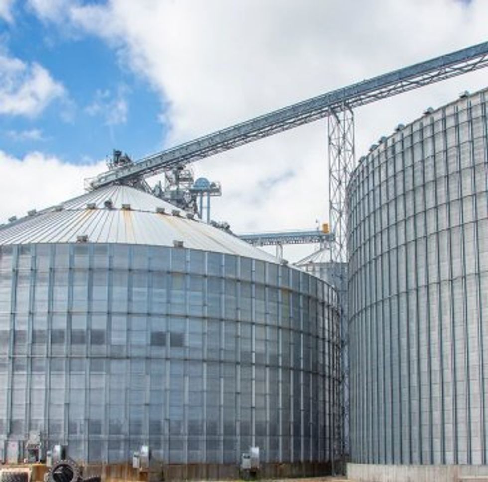
Specialized Industries

Interact With Our Compliance Experts

Upcoming Events