Be Part of the Ultimate Safety & Compliance Community
Trending news, knowledge-building content, and more – all personalized to you!


Based on the Environmental Protection Agency's (EPA's) reconsideration of the air quality criteria and the national ambient air quality standards (NAAQS) for particulate matter (PM), the EPA is revising the primary annual PM 2.5 standard by lowering the level from 12.0 µg/m 3 to 9.0 µg/m 3 . The Agency is retaining the current primary 24-hour PM 2.5 standard and the primary 24-hour PM 10 standard. The Agency also is not changing the secondary 24-hour PM 2.5 standard, secondary annual PM 2.5 standard, and secondary 24-hour PM 10 standard at this time. The EPA is also finalizing revisions to other key aspects related to the PM NAAQS, including revisions to the Air Quality Index (AQI) and monitoring requirements for the PM NAAQS.
DATES: This final rule is effective May 6, 2024, published in the Federal Register March 6, 2024, page 16202.
View final rule.
| §50.20 National primary ambient air quality standards for PM2.5. | ||
| Entire section | Added | View text |
| Appendix K to Part 50 - Interpretation of the National Ambient Air Quality Standards for Particulate Matter | ||
| Section 1.0 paragraph (b) | Revised | View text |
| Section 2.3 paragraph (d) | Added | View text |
| Section 3.0 paragraphs (a) and (b) | Added | View text |
| Appendix L to Part 50 - Reference Method for the Determination of Fine Particulate Matter as PM2.5 in the Atmosphere | ||
| Section 7.3.4 | Revised | View text |
| Section 7.3.4.5 | Added | View text |
| Appendix N to Part 50 - Interpretation of the National Ambient Air Quality Standards for PM2.5 | ||
| Section 1.0 paragraph (a) | Revised | View text |
| Section 3.0 paragraph (d)(3) | Added | View text |
| Section 4.1 paragraph (a) | Revised | View text |
| Section 4.2 paragraph (a) | Revised | View text |
| §53.4 Applications for reference or equivalent method determinations. | ||
| (a), (d) | Revised | View text |
| (b)(7) | Added | View text |
| §53.8 Designation of reference and equivalent methods. | ||
| (a) | Revised | View text |
| §53.14 Modification of a reference or equivalent method. | ||
| (c)(4)-(6) | Revised | View text |
| Table A–1 to Subpart A of Part 53—Summary of Applicable Requirements for Reference and Equivalent Methods for Air Monitoring of Criteria Pollutants | ||
| Entire table | Revised | View text |
| Table B-1 to Subpart B of Part 53- Performance Limit Specifications for Automated Methods | ||
| Footnote 4 | Revised | View text |
| Table B-3 to Subpart B of Part 53 - Interferent Test Concentration,1 Parts per Million | ||
| Entire table | Revised | View text |
| Appendix A to Subpart B of Part 53 - Optional Forms for Reporting Test Results | ||
| Figures B-3 and B-5 | Revised | View text |
| §53.35 Test procedure for Class II and Class III methods for PM2.5 and PM10−2.5. | ||
| (b)(1)(ii)(D) | Revised | View text |
| Table C-4 to Subpart C of Part 53—Test Specifications for PM10, PM2.5, and PM10–2.5 Candidate Equivalent Methods | ||
| Entire table | Revised | View text |
| §53.43 Test procedures. | ||
| Formulas in (a)(2)(xvi) and (c)(2)(iv) | Revised | View text |
| §53.51 Demonstration of compliance with design specifications and manufacturing and test requirements. | ||
| (d)(2) | Revised | View text |
| §53.61 Test conditions. | ||
| (g) | Revised | View text |
| §58.1 Definitions. | ||
| Definition for ”Approved regional method (ARM)” | Removed | View text |
| Definition for ”Traceable” | Removed | View text |
| §58.10 Annual monitoring network plan and periodic network assessment. | ||
| (a)(1), (b)(10), (b)(13), (d) | Revised | View text |
| (b)(14) | Added | View text |
| §58.11 Network technical requirements. | ||
| (a)(2), (e) | Revised | View text |
| §58.12 Operating schedules. | ||
| (d)(1) | Revised | View text |
| §58.15 Annual air monitoring data certification. | ||
| Entire section | Revised | View text |
| §58.20 Special purpose monitors (SPM). | ||
| (b)-(e) | Revised | View text |
| Appendix A to Part 58 - Quality Assurance Requirements for Monitors used in Evaluations of National Ambient Air Quality Standards | ||
| Entire appendix | Revised | View text |
| Appendix B to Part 58 - Quality Assurance Requirements for Prevention of Significant Deterioration (PSD) Air Monitoring | ||
| Entire appendix | View text | |
| Appendix C to Part 58—Ambient Air Quality Monitoring Methodology | ||
| Section 2 | Revised | View text |
| Appendix D to Part 58—Network Design Criteria for Ambient Air Quality Monitoring | ||
| Sections 1, 1.1(b), introductory text before table in 4.7.1(a), 4.7.1(b)(3), 4.7.2 | Revised | View text |
| Appendix E to Part 58—Probe and Monitoring Path Siting Criteria for Ambient Air Quality Monitoring | ||
| Entire appendix | Revised | View text |
| Appendix G to Part 58—Uniform Air Quality Index (AQI) and Daily Reporting | ||
| Entire appendix | Revised | View text |
New Text
Appendix K to Part 50 - Interpretation of the National Ambient Air Quality Standards for Particulate Matter
* * * *
(b) The terms used in this appendix are defined as follows:
Average refers to the arithmetic mean of the estimated number of exceedances per year, as per section 3.1 of this appendix.
Collocated monitors refer to two or more air measurement instruments for the same parameter (e.g., PM 10 mass) operated at the same site location, and whose placement is consistent with part 53 of this chapter. For purposes of considering a combined site record in this appendix, when two or more monitors are operated at the same site, one monitor is designated as the “primary” monitor with any additional monitors designated as “collocated.” It is implicit in these appendix procedures that the primary monitor and collocated monitor(s) are all reference or equivalent methods; however, it is not a requirement that the primary and collocated monitors utilize the same specific sampling and analysis method.
Combined site data record is the data set used for performing computations in this appendix and represents data for the primary monitors augmented with data from collocated monitors according to the procedure specified in section 3.0(a) of this appendix.
Daily value for PM10 refers to the 24-hour average concentration of PM 10 calculated or measured from midnight to midnight (local time).
Exceedance means a daily value that is above the level of the 24-hour standard after rounding to the nearest 10 µg/m 3i.e., values ending in 5 or greater are to be rounded up).
Expected annual value is the number approached when the annual values from an increasing number of years are averaged, in the absence of long-term trends in emissions or meteorological conditions.
Primary monitors are suitable monitors designated by a State or local agency in their annual network plan as the default data source for creating a combined site data record. If there is only one suitable monitor at a particular site location, then it is presumed to be a primary monitor.
Year refers to a calendar year.
Appendix L to Part 50 - Reference Method for the Determination of Fine Particulate Matter as PM2.5 in the Atmosphere
* * * *
7.3.4 Particle size separator. The sampler shall be configured with one of the three alternative particle size separators described in this section. One separator is an impactor-type separator (WINS impactor) described in sections 7.3.4.1, 7.3.4.2, and 7.3.4.3 of this appendix. One alternative separator is a cyclone-type separator (VSCC TM) described in section 7.3.4.4 of this appendix. The other alternative separator is also a cyclone-type separator (TE–PM 2.5 C) described in section 7.3.4.5 of this appendix.
Appendix N to Part 50 - Interpretation of the National Ambient Air Quality Standards for PM2.5
1.0 General
(a) This appendix explains the data handling conventions and computations necessary for determining when the national ambient air quality standards (NAAQS) for PM 2.5 are met, specifically the primary and secondary annual and 24-hour PM 2.5 NAAQS specified in §§50.7, 50.13, 50.18, and 50.20. PM 2.5 is defined, in general terms, as particles with an aerodynamic diameter less than or equal to a nominal 2.5 micrometers. PM 2.5 mass concentrations are measured in the ambient air by a Federal Reference Method (FRM) based on appendix L to this part, as applicable, and designated in accordance with part 53 of this chapter or by a Federal Equivalent Method (FEM) designated in accordance with part 53 of this chapter. Only those FRM and FEM measurements that are derived in accordance with part 58 of this chapter (i.e., that are deemed “suitable”) shall be used in comparisons with the PM 2.5 NAAQS. The data handling and computation procedures to be used to construct annual and 24-hour NAAQS metrics from reported PM 2.5 mass concentrations, and the associated instructions for comparing these calculated metrics to the levels of the PM 2.5 NAAQS, are specified in sections 2.0, 3.0, and 4.0 of this appendix.
* * * *
4.1 Annual PM2 . 5 NAAQS
(a) Levels of the primary and secondary annual PM 2.5 NAAQS are specified in §§50.7, 50.13, 50.18, and 50.20 as applicable.
* * * * *
4.2 Twenty-Four-Hour PM2 . 5 NAAQS
(a) Levels of the primary and secondary 24-hour PM 2.5 NAAQS are specified in §§50.7, 50.13, 50.18, and 50.20 as applicable.
§53.4 Applications for reference or equivalent method determinations.
(a) Applications for FRM or FEM determinations and modification requests of existing designated instruments shall be submitted to: U.S. Environmental Protection Agency, Director, Center for Environmental Measurement and Modeling, Reference and Equivalent Methods Designation Program (MD–D205–03), 109 T.W. Alexander Drive, P.O. Box 12055, Research Triangle Park, North Carolina 27711 (commercial delivery address: 4930 Old Page Road, Durham, North Carolina 27703).
* * * *
(d) For candidate reference or equivalent methods or for designated instruments that are the subject of a modification request, the applicant, if requested by EPA, shall provide to EPA a representative sampler or analyzer for test purposes. The sampler or analyzer shall be shipped free on board (FOB) destination to Director, Center for Environmental Measurements and Modeling, Reference and Equivalent Methods Designation Program (MD D205–03), U.S. Environmental Protection Agency, 4930 Old Page Road, Durham, North Carolina 27703, scheduled to arrive concurrently with or within 30 days of the arrival of the other application materials. This sampler or analyzer may be subjected to various tests that EPA determines to be necessary or appropriate under §53.5(f), and such tests may include special tests not described in this part. If the instrument submitted under this paragraph (d) malfunctions, becomes inoperative, or fails to perform as represented in the application before the necessary EPA testing is completed, the applicant shall be afforded the opportunity to repair or replace the device at no cost to the EPA. Upon completion of EPA testing, the sampler or analyzer submitted under this paragraph (d) shall be repacked by EPA for return shipment to the applicant, using the same packing materials used for shipping the instrument to EPA unless alternative packing is provided by the applicant. Arrangements for, and the cost of, return shipment shall be the responsibility of the applicant. The EPA does not warrant or assume any liability for the condition of the sampler or analyzer upon return to the applicant.
§53.8 Designation of reference and equivalent methods.
(a) A candidate method determined by the Administrator to satisfy the applicable requirements of this part shall be designated as an FRM or FEM (as applicable) by and upon publication of the designation in the Federal Register . Applicants shall not publicly announce, market, or sell the candidate sampler and analyzer as an approved FRM or FEM (as applicable) until the designation is published in the Federal Register .
§53.14 Modification of a reference or equivalent method.
* * * *
(c)(4) Send notice to the applicant that additional information must be submitted before a determination can be made and specify the additional information that is needed (in such cases, the 90-day period shall commence upon receipt of the additional information).
(c)(5) Send notice to the applicant that additional tests are necessary and specify which tests are necessary and how they shall be interpreted (in such cases, the 90-day period shall commence upon receipt of the additional test data).
(c)(6) Send notice to the applicant that additional tests will be conducted by the Administrator and specify the reasons for and the nature of the additional tests (in such cases, the 90-day period shall commence 1 calendar day after the additional tests are completed).
Table A–1 to Subpart A of Part 53—Summary of Applicable Requirements for Reference and Equivalent Methods for Air Monitoring of Criteria Pollutants
| 1 Some requirements may apply, based on the nature of each particular candidate method, as determined by the Administrator. | |||||||||
| 2 Alternative Class III requirements may be substituted. | |||||||||
| Pollutant | Reference or equivalent | Manual or automated | Applicable appendix of part 50 of this chapter | Applicable subparts of this part | |||||
| A | B | C | D | E | F | ||||
| SO 2 | Reference | Manual | A–2 | ||||||
| Automated | A–1 | ✓ | ✓ | ||||||
| Equivalent | Manual | A–1 | ✓ | ✓ | |||||
| Automated | A–1 | ✓ | ✓ | ✓ | |||||
| CO | Reference | Automated | C | ✓ | ✓ | ||||
| Equivalent | Manual | C | ✓ | ✓ | |||||
| Automated | C | ✓ | ✓ | ✓ | |||||
| O 3 | Reference | Automated | D | ✓ | ✓ | ||||
| Equivalent | Manual | D | ✓ | ✓ | |||||
| Automated | D | ✓ | ✓ | ✓ | |||||
| NO 2 | Reference | Automated | F | ✓ | ✓ | ||||
| Equivalent | Manual | F | ✓ | ✓ | |||||
| Automated | F | ✓ | ✓ | ✓ | |||||
| Pb | Reference | Manual | G | ||||||
| Equivalent | Manual | G | ✓ | ✓ | |||||
| Automated | G | ✓ | ✓ | ||||||
| PM 10 -Pb | Reference | Manual | Q | ||||||
| Equivalent | Manual | Q | ✓ | ✓ | |||||
| Automated | Q | ✓ | ✓ | ||||||
| PM 10 | Reference | Manual | J | ✓ | ✓ | ||||
| Equivalent | Manual | J | ✓ | ✓ | ✓ | ||||
| Automated | J | ✓ | ✓ | ✓ | |||||
| PM 2.5 | Reference | Manual | L | ✓ | ✓ | ||||
| Equivalent Class I | Manual | L | ✓ | ✓ | ✓ | ||||
| Equivalent Class II | Manual | L 1 | ✓ | 2 ✓ | ✓ | ✓ | |||
| Equivalent Class III | Automated | L 1 | ✓ | ✓ | ✓ | 1 ✓ | |||
| PM 10–2.5 | Reference | Manual | L, 2 O | ✓ | ✓ | ||||
| Equivalent Class I | Manual | L, 2 O | ✓ | ✓ | ✓ | ||||
| Equivalent Class II | Manual | L, 2 O | ✓ | 2 ✓ | ✓ | 1,2 ✓ | |||
| Equivalent Class III | Automated | 1 L, O | ✓ | ✓ | ✓ | 1 ✓ | |||
Table B-1 to Subpart B of Part 53- Performance Limit Specifications for Automated Methods
* * * *
4 For nitric oxide interference for the SO 2 ultraviolet fluorescence (UVF) method, interference equivalent is ±0.003 ppm for the lower range.
Table B-3 to Subpart B of Part 53 - Interferent Test Concentration,1 Parts per Million
| Pollutant | Analyzer type 2 | Hydro-chloric acid | Ammonia | Hydrogen sulfide | Sulfur dioxide | Nitrogen dioxide | Nitric oxide | Carbon dioxide | Ethylene | Ozone | M-xylene | Water vapor | Carbon monoxide | Methane | Ethane | Naphthalene |
|---|---|---|---|---|---|---|---|---|---|---|---|---|---|---|---|---|
| 1 Concentrations of interferent listed must be prepared and controlled to ±10 percent of the stated value. | ||||||||||||||||
| 2 Analyzer types not listed will be considered by the Administrator as special cases. | ||||||||||||||||
| 3 Do not mix interferent with the pollutant. | ||||||||||||||||
| 4 Concentration of pollutant used for test. These pollutant concentrations must be prepared to ±10 percent of the stated value. | ||||||||||||||||
| 5 If candidate method utilizes an elevated-temperature scrubber for removal of aromatic hydrocarbons, perform this interference test. | ||||||||||||||||
| 6 If naphthalene test concentration cannot be accurately quantified, remove the scrubber, use a test concentration that causes a full-scale response, reattach the scrubber, and evaluate response for interference. | ||||||||||||||||
| SO 2 | Ultraviolet fluorescence | 5 0.1 | 4 0.14 | 0.5 | 0.5 | 0.5 | 0.2 | 20,000 | 6 0.05 | |||||||
| SO 2 | Flame photometric | 0.01 | 4 0.14 | 750 | 3 20,000 | 50 | ||||||||||
| SO 2 | Gas chromatography | 0.1 | 4 0.14 | 750 | 3 20,000 | 50 | ||||||||||
| SO 2 | Spectrophotometric-wet chemical (pararosanaline) | 0.2 | 0.1 | 0.1 | 4 0.14 | 0.5 | 750 | 0.5 | ||||||||
| SO 2 | Electrochemical | 0.2 | 0.1 | 0.1 | 4 0.14 | 0.5 | 0.5 | 0.2 | 0.5 | 3 20,000 | ||||||
| SO 2 | Conductivity | 0.2 | 0.1 | 4 0.14 | 0.5 | 750 | ||||||||||
| SO 2 | Spectrophotometric-gas phase, including DOAS | 4 0.14 | 0.5 | 0.5 | 0.5 | 0.2 | ||||||||||
| O 3 | Ethylene Chemiluminescence | 3 0.1 | 750 | 4 0.08 | 3 20,000 | |||||||||||
| O 3 | NO-chemiluminescence | 3 0.1 | 0.5 | 750 | 4 0.08 | 3 20,000 | ||||||||||
| O 3 | Electrochemical | 3 0.1 | 0.5 | 0.5 | 4 0.08 | 3 20,000 | ||||||||||
| O 3 | Spectrophotometric-wet chemical (potassium iodide) | 3 0.1 | 0.5 | 0.5 | 3 0.5 | 4 0.08 | ||||||||||
| O 3 | Spectrophotometric-gas phase, including ultraviolet absorption and DOAS | 0.5 | 0.5 | 3 0.5 | 4 0.08 | 0.02 | 20,000 | |||||||||
| CO | Non-dispersive Infrared | 750 | 20,000 | 4 10 | ||||||||||||
| CO | Gas chromatography with flame ionization detector | 20,000 | 4 10 | 0.5 | ||||||||||||
| CO | Electrochemical | 0.5 | 0.2 | 20,000 | 4 10 | |||||||||||
| CO | Catalytic combustion-thermal detection | 0.1 | 750 | 0.2 | 20,000 | 4 10 | 5.0 | 0.5 | ||||||||
| CO | IR fluorescence | 750 | 20,000 | 4 10 | 0.5 | |||||||||||
| CO | Mercury replacement-UV photometric | 0.2 | 4 10 | 0.5 | ||||||||||||
| NO 2 | Chemiluminescent | 3 0.1 | 0.5 | 4 0.1 | 0.5 | 20,000 | ||||||||||
| NO 2 | Spectrophotometric-wet chemical (azo-dye reaction) | 0.5 | 4 0.1 | 0.5 | 750 | 0.5 | ||||||||||
| NO 2 | Electrochemical | 0.2 | 3 0.1 | 0.5 | 4 0.1 | 0.5 | 750 | 0.5 | 20,000 | 50 | ||||||
| NO 2 | Spectrophotometric-gas phase | 3 0.1 | 0.5 | 4 0.1 | 0.5 | 0.5 | 20,000 | 50 | ||||||||
Appendix A to Subpart B of Part 53 - Optional Forms for Reporting Test Results
* * * * *
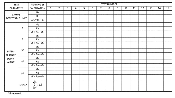
Figure B–3 to Appendix A to Subpart B of Part 53—Form for Test Data and Calculations for Lower Detectable Limit (LDL) and Interference Equivalent (IE) (see §53.23(c) and (d))
LDL Interference Test Data
Applicant _________________
Analyzer _________________
Date _________________
Pollutant _________________
* * * * *
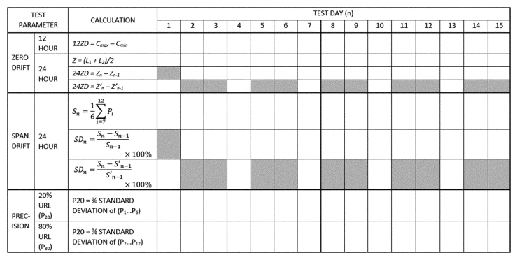
Figure B–5 to Appendix A to Subpart B of Part 53—Form for Calculating Zero Drift, Span Drift and Precision (see §53.23(e))
Calculation of Zero Drift, Span Drift, and Precision
Applicant _________________
Analyzer _________________
Date _________________
Pollutant _________________
§53.35 Test procedure for Class II and Class III methods for PM2.5 and PM10−2.5.
* * * *
(b)(1)(ii)(D) Site D shall be in a large city east of the Mississippi River, having characteristically high humidity levels.
Table C-4 to Subpart C of Part 53—Test Specifications for PM10, PM2.5, and PM10–2.5 Candidate Equivalent Methodss
| Specification | PM 10 | PM 2.5 | PM 10–2.5 | |||
|---|---|---|---|---|---|---|
| Class I | Class II | Class III | Class II | Class III | ||
| 1 Some missing daily measurement values may be permitted; see test procedure. | ||||||
| 2 Calculated as the root mean square over all measurement sets. | ||||||
| Acceptable concentration range (R j), µg/m 3 | 5–300 | 3–200 | 3–200 | 3–200 | 3–200 | 3–200. |
| Minimum number of test sites | 2 | 1 | 2 | 4 | 2 | 4. |
| Minimum number of candidate method samplers or analyzers per site | 3 | 3 | 3 1 | 3 1 | 3 1 | 3. 1 |
| Number of reference method samplers per site | 3 | 3 | 3 1 | 3 1 | 3 1 | 3. 1 |
| Minimum number of acceptable sample sets per site for PM 10 methods: | ||||||
| R j < 20 µg/m 3 | 3 | |||||
| R j > 20 µg/m 3 | 3 | |||||
| Total | 10 | |||||
| Minimum number of acceptable sample sets per site for PM 2.5 and PM 10–2.5 candidate equivalent methods: | ||||||
| R j < 15 µg/m 3 for 24-hr or R j < 8 µg/m 3 for 48-hr samples. | 3 | 3 | 3 | 3 | 3. | |
| Rj > 15 µg/m 3 for 24-hr or R j > 8 µg/m 3 for 48-hr samples | 3 | 3 | 3 | 3 | 3. | |
| Each season | 10 | 23 | 23 | 23 | 23. | |
| Total, each site | 10 | 23 | 23 (46 for two-season sites) | 23 | 23 (46 for two-season sites). | |
| Precision of replicate reference method measurements, P Rj or RP Rj , respectively; RP for Class II or III PM 2.5 or PM 10–2.5 , maximum | 5 μg/m 3 or 7%. | 2 μg/m 3 or 5%. | 10% 2 | 10% 2 | 10% 2 | 10%. 2 |
| Precision of PM 2.5 or PM 10–2.5 candidate method, CP, each site | 10% 2 | 15% 2 | 15% 2 | 15%. 2 | ||
| Slope of regression relationship | 1 ±0.10 | 1 ±0.05 | 1 ±0.10 | 1 ±0.10 | 1 ±0.10 | 1 ±0.12. |
| Intercept of regression relationship, µg/m 3 | 0 ±5 | 0 ±1 | Between: 13.55—(15.05 × slope), but not less than—1.5; and 16.56—(15.05 × slope), but not more than +1.5 | Between: 15.05—(17.32 × slope), but not less than—2.0; and 15.05—(13.20 × slope), but not more than +2.0 | Between: 62.05—(70.5 × slope), but not less than—3.5; and 78.95—(70.5 × slope), but not more than +3.5 | Between: 70.50—(82.93 × slope), but not less than—7.0; and 70.50—(61.16 × slope), but not more than +7.0. |
| Correlation of reference method and candidate method measurements | ≥ 0.97 | ≥ 0.97 | ≥ 0.93—for CCV ≤ 0.4; ≥ 0.85 + 0.2 × CCV—for 0.4 ≤ CCV ≤ 0.5; ≥ 0.95—for CCV ≥ 0.5 | |||
§53.43 Test procedures.
(a)(2)(xvi)
(c)(2)(iv) * * *
if C j is below 80 µg/m 3 , or
if C j is above 80 µg/m 3 .
§53.51 Demonstration of compliance with design specifications and manufacturing and test requirements.
* * * *
(d)(2) VSCC and TE–PM2.5C separators. For samplers and monitors utilizing the BGI VSCC or Tisch TE–PM 2.5 C particle size separators specified in sections 7.3.4.4 and 7.3.4.5 of appendix L to part 50 of this chapter, respectively, the respective manufacturers shall identify the critical dimensions and manufacturing tolerances for the separator, devise appropriate test procedures to verify that the critical dimensions and tolerances are maintained during the manufacturing process, and carry out those procedures on each separator manufactured to verify conformance of the manufactured products. The manufacturer shall also maintain records of these tests and their test results and submit evidence that this procedure is incorporated into the manufacturing procedure, that the test is or will be routinely implemented, and that an appropriate procedure is in place for the disposition of units that fail this tolerance tests.
§53.61 Test conditions.
(g) Vibrating Orifice Aerosol Generator (VOAG) and Flow-Focusing Monodisperse Aerosol Generator (FMAG) conventions. This section prescribes conventions regarding the use of the vibrating orifice aerosol generator (VOAG) and the flow-focusing monodisperse aerosol generator (FMAG) for the size-selective performance tests outlined in §§53.62, 53.63, 53.64, and 53.65.
(1) Particle aerodynamic diameter. The VOAG and FMAG produce near-monodisperse droplets through the controlled breakup of a liquid jet. When the liquid solution consists of a non-volatile solute dissolved in a volatile solvent, the droplets dry to form particles of near-monodisperse size.
(i) The physical diameter of a generated spherical particle can be calculated from the operational parameters of the VOAG and FMAG as:
Equation 1
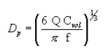
where:
Dp = particle physical diameter, µm;
Q = liquid volumetric flow rate, µm 3/sec;
Cvol = volume concentration (particle volume produced per drop volume), dimensionless; and
f = frequency of applied vibrational signal, 1/sec.
(ii) A given particle's aerodynamic behavior is a function of its physical particle size, particle shape, and density. Aerodynamic diameter is defined as the diameter of a unit density (ρo = 1g/cm 3) sphere having the same settling velocity as the particle under consideration. For converting a spherical particle of known density to aerodynamic diameter, the governing relationship is:
Equation 2
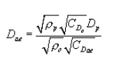
where:
Dae = particle aerodynamic diameter, µm;
ρp = particle density, g/cm 3;
ρo = aerodynamic particle density = 1 g/cm 3;
CDp = Cunningham's slip correction factor for physical particle diameter, dimensionless; and
CDae = Cunningham's slip correction factor for aerodynamic particle diameter, dimensionless.
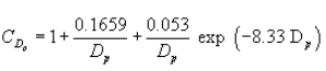
(iii) At room temperature and standard pressure, the Cunningham's slip correction factor is solely a function of particle diameter:
Equation 3
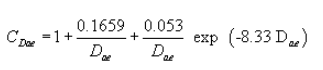
or
Equation 4
(iv) Since the slip correction factor is itself a function of particle diameter, the aerodynamic diameter in equation 2 of paragraph (g)(1)(ii) of this section cannot be solved directly but must be determined by iteration.
(2) Solid particle generation. (i) Solid particle tests performed in this subpart shall be conducted using particles composed of ammonium fluorescein. For use in the VOAG or FMAG, liquid solutions of known volumetric concentration can be prepared by diluting fluorescein powder (C 2 OH 12 O 5 , FW = 332.31, CAS 2321–07–5) with aqueous ammonia. Guidelines for preparation of fluorescein solutions of the desired volume concentration (C vol) are presented in Vanderpool and Rubow (1988) (Reference 2 in appendix A to this subpart). For purposes of converting particle physical diameter to aerodynamic diameter, an ammonium fluorescein particle density of 1.35 g/cm 3 shall be used.
(ii) Mass deposits of ammonium fluorescein shall be extracted and analyzed using solutions of 0.01 N ammonium hydroxide.
(iii) Calculation of the physical diameter of the particles produced by the VOAG and FMAG requires knowledge of the liquid solution's volume concentration (C vol). Because uranine is essentially insoluble in oleic acid, the total particle volume is the sum of the oleic acid volume and the uranine volume. The volume concentration of the liquid solution shall be calculated as:
Where:
V u = uranine volume, ml;
V oleic = oleic acid volume, ml;
V sol = total solution volume, ml;
M u = uranine mass, g;
P u = uranine density, g/cm 3 ;
M oleic = oleic acid mass, g; and
P oleic = oleic acid density, g/cm 3 .
(3) Liquid particle generation. (i) Tests prescribed in §53.63 for inlet aspiration require the use of liquid particle tests composed of oleic acid tagged with uranine to enable subsequent fluorometric quantitation of collected aerosol mass deposits. Oleic acid (C18H34O2, FW = 282.47, CAS 112-80-1) has a density of 0.8935 g/cm 3. Because the viscosity of oleic acid is relatively high, significant errors can occur when dispensing oleic acid using volumetric pipettes. For this reason, it is recommended that oleic acid solutions be prepared by quantifying dispensed oleic acid gravimetrically. The volume of oleic acid dispensed can then be calculated simply by dividing the dispensed mass by the oleic acid density.
(ii) Oleic acid solutions tagged with uranine shall be prepared as follows. A known mass of oleic acid shall first be diluted using absolute ethanol. The desired mass of the uranine tag should then be diluted in a separate container using absolute ethanol. Uranine (C20H10O5Na2, FW = 376.3, CAS 518-47-8) is the disodium salt of fluorescein and has a density of 1.53 g/cm 3. In preparing uranine tagged oleic acid particles, the uranine content shall not exceed 20 percent on a mass basis. Once both oleic acid and uranine solutions are properly prepared, they can then be combined and diluted to final volume using absolute ethanol.
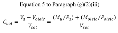
(iii) Calculation of the physical diameter of the particles produced by the VOAG requires knowledge of the liquid solution's volume concentration (Cvol). Because uranine is essentially insoluble in oleic acid, the total particle volume is the sum of the oleic acid volume and the uranine volume. The volume concentration of the liquid solution shall be calculated as:
Equation 5
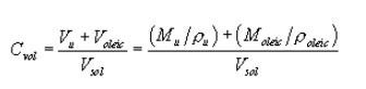
where:
Vu = uranine volume, ml;
Voleic = oleic acid volume, ml;
Vsol = total solution volume, ml;
Mu = uranine mass, g;
ρu = uranine density, g/cm 3;
Moleic = oleic acid mass, g; and
ρoleic = oleic acid density, g/cm. 3
(iv) For purposes of converting the particles' physical diameter to aerodynamic diameter, the density of the generated particles shall be calculated as:
Equation 6

(v) Mass deposits of oleic acid shall be extracted and analyzed using solutions of 0.01 N sodium hydroxide.
§58.1 Definitions.
* * * *
Traceable means a measurement result from a local standard whereby the result can be related to the International System of Units (SI) through a documented unbroken chain of calibrations, each contributing to the measurement uncertainty. Traceable measurement results must be compared and certified, either directly or via not more than one intermediate standard, to a National Institute of Standards and Technology (NIST)-certified reference standard. Examples include but are not limited to NIST Standard Reference Material (SRM), NIST-traceable Reference Material (NTRM), or a NIST-certified Research Gas Mixture (RGM). Traceability to the SI through other National Metrology Institutes (NMIs) in addition to NIST is allowed if a Declaration of Equivalence (DoE) exists between NIST and that NMI.
§58.10 Annual monitoring network plan and periodic network assessment.
* * * *
(a)(1) Beginning July 1, 2007, the State, or where applicable local, agency shall submit to the Regional Administrator an annual monitoring network plan which shall provide for the documentation of the establishment and maintenance of an air quality surveillance system that consists of a network of SLAMS monitoring stations that can include FRM and FEM monitors that are part of SLAMS, NCore, CSN, PAMS, and SPM stations. The plan shall include a statement of whether the operation of each monitor meets the requirements of appendices A, B, C, D, and E to this part, where applicable. The Regional Administrator may require additional information in support of this statement. The annual monitoring network plan must be made available for public inspection and comment for at least 30 days prior to submission to the EPA and the submitted plan shall include and address, as appropriate, any received comments.
* * * * *
(b)(10) Any monitors for which a waiver has been requested or granted by the EPA Regional Administrator as allowed for under appendix D or appendix E to this part. For those monitors where a waiver has been approved, the annual monitoring network plan shall include the date the waiver was approved.
* * * * *
(b)(13) The identification of any PM 2.5 FEMs used in the monitoring agency's network where the data are not of sufficient quality such that data are not to be compared to the national ambient air quality standards (NAAQS). For required SLAMS where the agency identifies that the PM 2.5 Class III FEM does not produce data of sufficient quality for comparison to the NAAQS, the monitoring agency must ensure that an operating FRM or filter-based FEM meeting the sample frequency requirements described in §58.12 or other Class III PM 2.5 FEM with data of sufficient quality is operating and reporting data to meet the network design criteria described in appendix D to this part.
* * * * *
(d) The State, or where applicable local, agency shall perform and submit to the EPA Regional Administrator an assessment of the air quality surveillance system every 5 years to determine, at a minimum, if the network meets the monitoring objectives defined in appendix D to this part, whether new sites are needed, whether existing sites are no longer needed and can be terminated, and whether new technologies are appropriate for incorporation into the ambient air monitoring network. The network assessment must consider the ability of existing and proposed sites to support air quality characterization for areas with relatively high populations of susceptible individuals (e.g., children with asthma) and other at-risk populations, and, for any sites that are being proposed for discontinuance, the effect on data users other than the agency itself, such as nearby States and Tribes or health effects studies. The State, or where applicable local, agency must submit a copy of this 5-year assessment, along with a revised annual network plan, to the Regional Administrator. The assessments are due every 5 years beginning July 1, 2010.
§58.11 Network technical requirements.
* * * *
(a)(2) Beginning January 1, 2009, State and local governments shall follow the quality assurance criteria contained in appendix A to this part that apply to SPM sites when operating any SPM site which uses an FRM or an FEM and meets the requirements of appendix E to this part, unless the Regional Administrator approves an alternative to the requirements of appendix A with respect to such SPM sites because meeting those requirements would be physically and/or financially impractical due to physical conditions at the monitoring site and the requirements are not essential to achieving the intended data objectives of the SPM site. Alternatives to the requirements of appendix A may be approved for an SPM site as part of the approval of the annual monitoring plan, or separately.
* * * *
(e) State and local governments must assess data from Class III PM 2.5 FEM monitors operated within their network using the performance criteria described in table C–4 to subpart C of part 53 of this chapter, for cases where the data are identified as not of sufficient comparability to a collocated FRM, and the monitoring agency requests that the FEM data should not be used in comparison to the NAAQS. These assessments are required in the monitoring agency's annual monitoring network plan described in §58.10(b) for cases where the FEM is identified as not of sufficient comparability to a collocated FRM. For these collocated PM 2.5 monitors, the performance criteria apply with the following additional provisions:
(1) The acceptable concentration range (Rj), µg/m 3 may include values down to 0 µg/m 3 .
(2) The minimum number of test sites shall be at least one; however, the number of test sites will generally include all locations within an agency's network with collocated FRMs and FEMs.
(3) The minimum number of methods shall include at least one FRM and at least one FEM.
(4) Since multiple FRMs and FEMs may not be present at each site, the precision statistic requirement does not apply, even if precision data are available.
(5) All seasons must be covered with no more than 36 consecutive months of data in total aggregated together.
(6) The key statistical metric to include in an assessment is the bias (both additive and multiplicative) of the PM 2.5 continuous FEM(s) compared to a collocated FRM(s). Correlation is required to be reported in the assessment, but failure to meet the correlation criteria, by itself, is not cause to exclude data from a continuous FEM monitor.
§58.12 Operating schedules.
* * * *
(1)(i) Manual PM 2.5 samplers at required SLAMS stations without a collocated continuously operating PM 2.5 monitor must operate on at least a 1-in-3 day schedule unless a waiver for an alternative schedule has been approved per paragraph (d)(1)(ii) of this section.
(ii) For SLAMS PM 2.5 sites with both manual and continuous PM 2.5 monitors operating, the monitoring agency may request approval for a reduction to 1-in-6 day PM 2.5 sampling or for seasonal sampling from the EPA Regional Administrator. Other requests for a reduction to 1-in-6 day PM 2.5 sampling or for seasonal sampling may be approved on a case-by-case basis. The EPA Regional Administrator may grant sampling frequency reductions after consideration of factors (including but not limited to the historical PM 2.5 data quality assessments, the location of current PM 2.5 design value sites, and their regulatory data needs) if the Regional Administrator determines that the reduction in sampling frequency will not compromise data needed for implementation of the NAAQS. Required SLAMS stations whose measurements determine the design value for their area and that are within plus or minus 10 percent of the annual NAAQS, and all required sites where one or more 24-hour values have exceeded the 24-hour NAAQS each year for a consecutive period of at least 3 years are required to maintain at least a 1-in-3 day sampling frequency until the design value no longer meets the criteria in this paragraph (d)(1)(ii) for 3 consecutive years. A continuously operating FEM PM 2.5 monitor satisfies the requirement in this paragraph (d)(1)(ii) unless it is identified in the monitoring agency's annual monitoring network plan as not appropriate for comparison to the NAAQS and the EPA Regional Administrator has approved that the data from that monitor may be excluded from comparison to the NAAQS.
(iii) Required SLAMS stations whose measurements determine the 24-hour design value for their area and whose data are within plus or minus 5 percent of the level of the 24-hour PM 2.5 NAAQS must have an FRM or FEM operate on a daily schedule if that area's design value for the annual NAAQS is less than the level of the annual PM 2.5 standard. A continuously operating FEM or PM 2.5 monitor satisfies the requirement in this paragraph (d)(1)(iii) unless it is identified in the monitoring agency's annual monitoring network plan as not appropriate for comparison to the NAAQS and the EPA Regional Administrator has approved that the data from that monitor may be excluded from comparison to the NAAQS. The daily schedule must be maintained until the referenced design values no longer meets the criteria in this paragraph (d)(1)(iii) for 3 consecutive years.
(iv) Changes in sampling frequency attributable to changes in design values shall be implemented no later than January 1 of the calendar year following the certification of such data as described in §58.15.
§58.15 Annual air monitoring data certification.
(a) The State, or where appropriate local, agency shall submit to the EPA Regional Administrator an annual air monitoring data certification letter to certify data collected by FRM and FEM monitors at SLAMS and SPM sites that meet criteria in appendix A to this part from January 1 to December 31 of the previous year. The head official in each monitoring agency, or his or her designee, shall certify that the previous year of ambient concentration and quality assurance data are completely submitted to AQS and that the ambient concentration data are accurate to the best of her or his knowledge, taking into consideration the quality assurance findings. The annual data certification letter is due by May 1 of each year.
(b) Along with each certification letter, the State shall submit to the Regional Administrator an annual summary report of all the ambient air quality data collected by FRM and FEM monitors at SLAMS and SPM sites. The annual report(s) shall be submitted for data collected from January 1 to December 31 of the previous year. The annual summary serves as the record of the specific data that is the object of the certification letter.
(c) Along with each certification letter, the State shall submit to the Regional Administrator a summary of the precision and accuracy data for all ambient air quality data collected by FRM and FEM monitors at SLAMS and SPM sites. The summary of precision and accuracy shall be submitted for data collected from January 1 to December 31 of the previous year.
§58.20 Special purpose monitors (SPM).
* * * *
(b) Any SPM data collected by an air monitoring agency using a Federal reference method (FRM) or Federal equivalent method (FEM) must meet the requirements of §§58.11 and 58.12 and appendix A to this part or an approved alternative to appendix A. Compliance with appendix E to this part is optional but encouraged except when the monitoring agency's data objectives are inconsistent with the requirements in appendix E. Data collected at an SPM using a FRM or FEM meeting the requirements of appendix A must be submitted to AQS according to the requirements of §58.16. Data collected by other SPMs may be submitted. The monitoring agency must also submit to AQS an indication of whether each SPM reporting data to AQS monitor meets the requirements of appendices A and E.
(c) All data from an SPM using an FRM or FEM which has operated for more than 24 months are eligible for comparison to the relevant NAAQS, subject to the conditions of §§58.11(e) and 58.30, unless the air monitoring agency demonstrates that the data came from a particular period during which the requirements of appendix A, appendix C, or appendix E to this part were not met, subject to review and EPA Regional Office approval as part of the annual monitoring network plan described in §58.10.
(d) If an SPM using an FRM or FEM is discontinued within 24 months of start-up, the Administrator will not base a NAAQS violation determination for the PM 2.5 or ozone NAAQS solely on data from the SPM.
(e) If an SPM using an FRM or FEM is discontinued within 24 months of start-up, the Administrator will not designate an area as nonattainment for the CO, SO 2 , NO 2 , or 24-hour PM 10 NAAQS solely on the basis of data from the SPM. Such data are eligible for use in determinations of whether a nonattainment area has attained one of these NAAQS.
Appendix A to Part 58 - Quality Assurance Requirements for Monitors used in Evaluations of National Ambient Air Quality Standards
1. General Information
2. Quality System Requirements
3. Measurement Quality Check Requirements
4. Calculations for Data Quality Assessments
5. Reporting Requirements
6. References
1. General Information
1.1 Applicability. (a) This appendix specifies the minimum quality system requirements applicable to SLAMS and other monitor types whose data are intended to be used to determine compliance with the NAAQS (e.g., SPMs, tribal, CASTNET, NCore, industrial, etc.), unless the EPA Regional Administrator has reviewed and approved the monitor for exclusion from NAAQS use and these quality assurance requirements.
(b) Primary quality assurance organizations are encouraged to develop and maintain quality systems more extensive than the required minimums. Additional guidance for the requirements reflected in this appendix can be found in the “Quality Assurance Handbook for Air Pollution Measurement Systems,” Volume II (see reference 10 of this appendix) and at a national level in references 1, 2, and 3 of this appendix.
1.2 Primary Quality Assurance Organization (PQAO). A PQAO is defined as a monitoring organization or a group of monitoring organizations or other organization that is responsible for a set of stations that monitors the same pollutant and for which data quality assessments will be pooled. Each criteria pollutant sampler/monitor must be associated with only one PQAO. In some cases, data quality is assessed at the PQAO level.
1.2.1 Each PQAO shall be defined such that measurement uncertainty among all stations in the organization can be expected to be reasonably homogeneous as a result of common factors. Common factors that should be considered in defining PQAOs include:
(a) Operation by a common team of field operators according to a common set of procedures;
(b) Use of a common quality assurance project plan (QAPP) or standard operating procedures;
(c) Common calibration facilities and standards;
(d) Oversight by a common quality assurance organization; and
(e) Support by a common management organization (i.e., state agency) or laboratory.
Since data quality assessments are made and data certified at the PQAO level, the monitoring organization identified as the PQAO will be responsible for the oversight of the quality of data of all monitoring organizations within the PQAO.
1.2.2 Monitoring organizations having difficulty describing its PQAO or in assigning specific monitors to primary quality assurance organizations should consult with the appropriate EPA Regional Office. Any consolidation of monitoring organizations to PQAOs shall be subject to final approval by the appropriate EPA Regional Office.
1.2.3 Each PQAO is required to implement a quality system that provides sufficient information to assess the quality of the monitoring data. The quality system must, at a minimum, include the specific requirements described in this appendix. Failure to conduct or pass a required check or procedure, or a series of required checks or procedures, does not by itself invalidate data for regulatory decision making. Rather, PQAOs and the EPA shall use the checks and procedures required in this appendix in combination with other data quality information, reports, and similar documentation that demonstrate overall compliance with Part 58. Accordingly, the EPA and PQAOs shall use a “weight of evidence” approach when determining the suitability of data for regulatory decisions. The EPA reserves the authority to use or not use monitoring data submitted by a monitoring organization when making regulatory decisions based on the EPA's assessment of the quality of the data. Consensus built validation templates or validation criteria already approved in QAPPs should be used as the basis for the weight of evidence approach.
1.3 Definitions.
(a) Measurement Uncertainty. A term used to describe deviations from a true concentration or estimate that are related to the measurement process and not to spatial or temporal population attributes of the air being measured.
(b) Precision. A measurement of mutual agreement among individual measurements of the same property usually under prescribed similar conditions, expressed generally in terms of the standard deviation.
(c) Bias. The systematic or persistent distortion of a measurement process which causes errors in one direction.
(d) Accuracy. The degree of agreement between an observed value and an accepted reference value. Accuracy includes a combination of random error (imprecision) and systematic error (bias) components which are due to sampling and analytical operations.
(e) Completeness. A measure of the amount of valid data obtained from a measurement system compared to the amount that was expected to be obtained under correct, normal conditions.
(f) Detection Limit. The lowest concentration or amount of target analyte that can be determined to be different from zero by a single measurement at a stated level of probability.
1.4 Measurement Quality Checks. The measurement quality checks described in section 3 of this appendix shall be reported to AQS and are included in the data required for certification.
1.5 Assessments and Reports. Periodic assessments and documentation of data quality are required to be reported to the EPA. To provide national uniformity in this assessment and reporting of data quality for all networks, specific assessment and reporting procedures are prescribed in detail in sections 3, 4, and 5 of this appendix. On the other hand, the selection and extent of the quality assurance and quality control activities used by a monitoring organization depend on a number of local factors such as field and laboratory conditions, the objectives for monitoring, the level of data quality needed, the expertise of assigned personnel, the cost of control procedures, pollutant concentration levels, etc. Therefore, quality system requirements in section 2 of this appendix are specified in general terms to allow each monitoring organization to develop a quality system that is most efficient and effective for its own circumstances while achieving the data quality objectives described in this appendix.
2. Quality System Requirements
A quality system (reference 1 of this appendix) is the means by which an organization manages the quality of the monitoring information it produces in a systematic, organized manner. It provides a framework for planning, implementing, assessing and reporting work performed by an organization and for carrying out required quality assurance and quality control activities.
2.1 Quality Management Plans and Quality Assurance Project Plans. All PQAOs must develop a quality system that is described and approved in quality management plans (QMP) and QAPPs to ensure that the monitoring results:
(a) Meet a well-defined need, use, or purpose (reference 5 of this appendix);
(b) Provide data of adequate quality for the intended monitoring objectives;
(c) Satisfy stakeholder expectations;
(d) Comply with applicable standards specifications;
(e) Comply with statutory (and other legal) requirements; and
(f) Reflect consideration of cost and economics.
2.1.1 The QMP describes the quality system in terms of the organizational structure, functional responsibilities of management and staff, lines of authority, and required interfaces for those planning, implementing, assessing and reporting activities involving environmental data operations (EDO). The QMP must be suitably documented in accordance with EPA requirements (reference 2 of this appendix), and approved by the appropriate Regional Administrator, or his or her representative. The quality system described in the QMP will be reviewed during the systems audits described in section 2.5 of this appendix. Organizations that implement long-term monitoring programs with EPA funds should have a separate QMP document. Smaller organizations, organizations that do infrequent work with the EPA or have monitoring programs of limited size or scope may combine the QMP with the QAPP if approved by, and subject to any conditions of the EPA. Additional guidance on this process can be found in reference 10 of this appendix. Approval of the recipient's QMP by the appropriate Regional Administrator or his or her representative may allow delegation of authority to the PQAOs independent quality assurance function to review and approve environmental data collection activities adequately described and covered under the scope of the QMP and documented in appropriate planning documents (QAPP). Where a PQAO or monitoring organization has been delegated authority to review and approve their QAPP, an electronic copy must be submitted to the EPA region at the time it is submitted to the PQAO/monitoring organization's QAPP approving authority. The QAPP will be reviewed by the EPA during systems audits or circumstances related to data quality. The QMP submission and approval dates for PQAOs/monitoring organizations must be reported to AQS either by the monitoring organization or the EPA Region.
2.1.2 The QAPP is a formal document describing, in sufficient detail, the quality system that must be implemented to ensure that the results of work performed will satisfy the stated objectives. PQAOs must develop QAPPs that describe how the organization intends to control measurement uncertainty to an appropriate level in order to achieve the data quality objectives for the EDO. The quality assurance policy of the EPA requires every EDO to have a written and approved QAPP prior to the start of the EDO. It is the responsibility of the PQAO/monitoring organization to adhere to this policy. The QAPP must be suitably documented in accordance with EPA requirements (reference 3 of this appendix) and include standard operating procedures for all EDOs either within the document or by appropriate reference. The QAPP must identify each PQAO operating monitors under the QAPP as well as generally identify the sites and monitors to which it is applicable either within the document or by appropriate reference. The QAPP submission and approval dates must be reported to AQS either by the monitoring organization or the EPA Region.
2.1.3 The PQAO/monitoring organization's quality system must have adequate resources both in personnel and funding to plan, implement, assess and report on the achievement of the requirements of this appendix and it's approved QAPP.
2.2 Independence of Quality Assurance. The PQAO must provide for a quality assurance management function, that aspect of the overall management system of the organization that determines and implements the quality policy defined in a PQAO's QMP. Quality management includes strategic planning, allocation of resources and other systematic planning activities (e.g., planning, implementation, assessing and reporting) pertaining to the quality system. The quality assurance management function must have sufficient technical expertise and management authority to conduct independent oversight and assure the implementation of the organization's quality system relative to the ambient air quality monitoring program and should be organizationally independent of environmental data generation activities.
2.3. Data Quality Performance Requirements.
2.3.1 Data Quality Objectives. The DQOs, or the results of other systematic planning processes, are statements that define the appropriate type of data to collect and specify the tolerable levels of potential decision errors that will be used as a basis for establishing the quality and quantity of data needed to support the monitoring objectives (reference 5 of this appendix). The DQOs will be developed by the EPA to support the primary regulatory objectives for each criteria pollutant. As they are developed, they will be added to the regulation. The quality of the conclusions derived from data interpretation can be affected by population uncertainty (spatial or temporal uncertainty) and measurement uncertainty (uncertainty associated with collecting, analyzing, reducing and reporting concentration data). This appendix focuses on assessing and controlling measurement uncertainty.
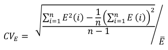
2.3.1.1 Measurement Uncertainty for Automated and Manual PM2.5Methods. The goal for acceptable measurement uncertainty is defined for precision as an upper 90 percent confidence limit for the coefficient of variation (CV) of 10 percent and ±10 percent for total bias.
2.3.1.2 Measurement Uncertainty for Automated O3Methods. The goal for acceptable measurement uncertainty is defined for precision as an upper 90 percent confidence limit for the CV of 7 percent and for bias as an upper 95 percent confidence limit for the absolute bias of 7 percent.
2.3.1.3 Measurement Uncertainty for Pb Methods. The goal for acceptable measurement uncertainty is defined for precision as an upper 90 percent confidence limit for the CV of 20 percent and for bias as an upper 95 percent confidence limit for the absolute bias of 15 percent.
2.3.1.4 Measurement Uncertainty for NO2. The goal for acceptable measurement uncertainty is defined for precision as an upper 90 percent confidence limit for the CV of 15 percent and for bias as an upper 95 percent confidence limit for the absolute bias of 15 percent.
2.3.1.5 Measurement Uncertainty for SO2. The goal for acceptable measurement uncertainty for precision is defined as an upper 90 percent confidence limit for the CV of 10 percent and for bias as an upper 95 percent confidence limit for the absolute bias of 10 percent.
2.4 National Performance Evaluation Programs. The PQAO shall provide for the implementation of a program of independent and adequate audits of all monitors providing data for NAAQS compliance purposes including the provision of adequate resources for such audit programs. A monitoring plan (or QAPP) which provides for PQAO participation in the EPA's National Performance Audit Program (NPAP), the PM2.5 Performance Evaluation Program (PM2.5-PEP) program and the Pb Performance Evaluation Program (Pb-PEP) and indicates the consent of the PQAO for the EPA to apply an appropriate portion of the grant funds, which the EPA would otherwise award to the PQAO for these QA activities, will be deemed by the EPA to meet this requirement. For clarification and to participate, PQAOs should contact either the appropriate EPA regional quality assurance (QA) coordinator at the appropriate EPA Regional Office location, or the NPAP coordinator at the EPA Air Quality Assessment Division, Office of Air Quality Planning and Standards, in Research Triangle Park, North Carolina. The PQAOs that plan to implement these programs (self-implement) rather than use the federal programs must meet the adequacy requirements found in the appropriate sections that follow, as well as meet the definition of independent assessment that follows.
2.4.1 Independent assessment. An assessment performed by a qualified individual, group, or organization that is not part of the organization directly performing and accountable for the work being assessed. This auditing organization must not be involved with the generation of the ambient air monitoring data. An organization can conduct the performance evaluation (PE) if it can meet this definition and has a management structure that, at a minimum, will allow for the separation of its routine sampling personnel from its auditing personnel by two levels of management. In addition, the sample analysis of audit filters must be performed by a laboratory facility and laboratory equipment separate from the facilities used for routine sample analysis. Field and laboratory personnel will be required to meet PE field and laboratory training and certification requirements to establish comparability to federally implemented programs.
2.5 Technical Systems Audit Program. Technical systems audits of each PQAO shall be conducted at least every 3 years by the appropriate EPA Regional Office and reported to the AQS. If a PQAO is made up of more than one monitoring organization, all monitoring organizations in the PQAO should be audited within 6 years (two TSA cycles of the PQAO). As an example, if a state has five local monitoring organizations that are consolidated under one PQAO, all five local monitoring organizations should receive a technical systems audit within a 6-year period. Systems audit programs are described in reference 10 of this appendix.
2.6 Gaseous and Flow Rate Audit Standards.
2.6.1 Gaseous pollutant concentration standards (permeation devices or cylinders of compressed gas) used to obtain test concentrations for CO, SO 2 , NO, and NO 2 must be EPA Protocol Gases certified in accordance with one of the procedures given in Reference 4 of this appendix.
2.6.1.1 The concentrations of EPA Protocol Gas standards used for ambient air monitoring must be certified with a 95-percent confidence interval to have an analytical uncertainty of no more than ±2.0 percent (inclusive) of the certified concentration (tag value) of the gas mixture. The uncertainty must be calculated in accordance with the statistical procedures defined in Reference 4 of this appendix.
2.6.1.2 Specialty gas producers advertising certification with the procedures provided in Reference 4 of this appendix and distributing gases as “EPA Protocol Gas” for ambient air monitoring purposes must adhere to the regulatory requirements specified in 40 CFR 75.21(g) or not use “EPA” in any form of advertising. Monitoring organizations must provide information to the EPA on the specialty gas producers they use on an annual basis. PQAOs, when requested by the EPA, must participate in the EPA Ambient Air Protocol Gas Verification Program at least once every 5 years by sending a new unused standard to a designated verification laboratory.
2.6.2 Test concentrations for O3 must be obtained in accordance with the ultraviolet photometric calibration procedure specified in appendix D to Part 50 of this chapter and by means of a certified NIST-traceable O3 transfer standard. Consult references 7 and 8 of this appendix for guidance on transfer standards for O3.
2.6.3 Flow rate measurements must be made by a flow measuring instrument that is NIST-traceable to an authoritative volume or other applicable standard. Guidance for certifying some types of flowmeters is provided in reference 10 of this appendix.
2.7 Primary Requirements and Guidance. Requirements and guidance documents for developing the quality system are contained in references 1 through 11 of this appendix, which also contain many suggested procedures, checks, and control specifications. Reference 10 describes specific guidance for the development of a quality system for data collected for comparison to the NAAQS. Many specific quality control checks and specifications for methods are included in the respective reference methods described in Part 50 of this chapter or in the respective equivalent method descriptions available from the EPA (reference 6 of this appendix). Similarly, quality control procedures related to specifically designated reference and equivalent method monitors are contained in the respective operation or instruction manuals associated with those monitors.
3. Measurement Quality Check Requirements
This section provides the requirements for PQAOs to perform the measurement quality checks that can be used to assess data quality. Data from these checks are required to be submitted to the AQS within the same time frame as routinely-collected ambient concentration data as described in 40 CFR 58.16. Table A-1 of this appendix provides a summary of the types and frequency of the measurement quality checks that will be described in this section.
3.1. Gaseous Monitors of SO2, NO2, O3, and CO.
3.1.1 One-Point Quality Control (QC) Check for SO2, NO2, O3, and CO. (a) A one-point QC check must be performed at least once every 2 weeks on each automated monitor used to measure SO2, NO2, O3 and CO. With the advent of automated calibration systems, more frequent checking is strongly encouraged. See Reference 10 of this appendix for guidance on the review procedure. The QC check is made by challenging the monitor with a QC check gas of known concentration (effective concentration for open path monitors) between the prescribed range of 0.005 and 0.08 parts per million (ppm) for SO2, NO2, and O3, and between the prescribed range of 0.5 and 5 ppm for CO monitors. The QC check gas concentration selected within the prescribed range should be related to the monitoring objectives for the monitor. If monitoring at an NCore site or for trace level monitoring, the QC check concentration should be selected to represent the mean or median concentrations at the site. If the mean or median concentrations at trace gas sites are below the MDL of the instrument the agency can select the lowest concentration in the prescribed range that can be practically achieved. If the mean or median concentrations at trace gas sites are above the prescribed range the agency can select the highest concentration in the prescribed range. An additional QC check point is encouraged for those organizations that may have occasional high values or would like to confirm the monitors' linearity at the higher end of the operational range or around NAAQS concentrations. If monitoring for NAAQS decisions, the QC concentration can be selected at a higher concentration within the prescribed range but should also consider precision points around mean or median monitor concentrations.
(b) Point analyzers must operate in their normal sampling mode during the QC check and the test atmosphere must pass through all filters, scrubbers, conditioners and other components used during normal ambient sampling and as much of the ambient air inlet system as is practicable. The QC check must be conducted before any calibration or adjustment to the monitor.
(c) Open path monitors are tested by inserting a test cell containing a QC check gas concentration into the optical measurement beam of the instrument. If possible, the normally used transmitter, receiver, and as appropriate, reflecting devices should be used during the test, and the normal monitoring configuration of the instrument should be altered as little as possible to accommodate the test cell for the test. However, if permitted by the associated operation or instruction manual, an alternate local light source or an alternate optical path that does not include the normal atmospheric monitoring path may be used. The actual concentration of the QC check gas in the test cell must be selected to produce an effective concentration in the range specified earlier in this section. Generally, the QC test concentration measurement will be the sum of the atmospheric pollutant concentration and the QC test concentration. As such, the result must be corrected to remove the atmospheric concentration contribution. The corrected concentration is obtained by subtracting the average of the atmospheric concentrations measured by the open path instrument under test immediately before and immediately after the QC test from the QC check gas concentration measurement. If the difference between these before and after measurements is greater than 20 percent of the effective concentration of the test gas, discard the test result and repeat the test. If possible, open path monitors should be tested during periods when the atmospheric pollutant concentrations are relatively low and steady.
(d) Report the audit concentration of the QC gas and the corresponding measured concentration indicated by the monitor to AQS. The percent differences between these concentrations are used to assess the precision and bias of the monitoring data as described in sections 4.1.2 (precision) and 4.1.3 (bias) of this appendix.
3.1.2 Annual performance evaluation for SO2, NO2, O3, or CO. A performance evaluation must be conducted on each primary monitor once a year. This can be accomplished by evaluating 25 percent of the primary monitors each quarter. The evaluation should be conducted by a trained experienced technician other than the routine site operator.
3.1.2.1 The evaluation is made by challenging the monitor with audit gas standards of known concentration from at least three audit levels. One point must be within two to three times the method detection limit of the instruments within the PQAOs network, the second point will be less than or equal to the 99th percentile of the data at the site or the network of sites in the PQAO or the next highest audit concentration level. The third point can be around the primary NAAQS or the highest 3-year concentration at the site or the network of sites in the PQAO. An additional 4th level is encouraged for those agencies that would like to confirm the monitors' linearity at the higher end of the operational range. In rare circumstances, there may be sites measuring concentrations above audit level 10. Notify the appropriate EPA region and the AQS program in order to make accommodations for auditing at levels above level 10.
| Audit level | Concentration Range, ppm | |||
|---|---|---|---|---|
| O3 | SO2 | NO2 | CO | |
| 1 | 0.004-0.0059 | 0.0003-0.0029 | 0.0003-0.0029 | 0.020-0.059 |
| 2 | 0.006-0.019 | 0.0030-0.0049 | 0.0030-0.0049 | 0.060-0.199 |
| 3 | 0.020-0.039 | 0.0050-0.0079 | 0.0050-0.0079 | 0.200-0.899 |
| 4 | 0.040-0.069 | 0.0080-0.0199 | 0.0080-0.0199 | 0.900-2.999 |
| 5 | 0.070-0.089 | 0.0200-0.0499 | 0.0200-0.0499 | 3.000-7.999 |
| 6 | 0.090-0.119 | 0.0500-0.0999 | 0.0500-0.0999 | 8.000-15.999 |
| 7 | 0.120-0.139 | 0.1000-0.1499 | 0.1000-0.2999 | 16.000-30.999 |
| 8 | 0.140-0.169 | 0.1500-0.2599 | 0.3000-0.4999 | 31.000-39.999 |
| 9 | 0.170-0.189 | 0.2600-0.7999 | 0.5000-0.7999 | 40.000-49.999 |
| 10 | 0.190-0.259 | 0.8000-1.000 | 0.8000-1.000 | 50.000-60.000 |
3.1.2.2 The standards from which audit gas test concentrations are obtained must meet the specifications of section 2.6.1 of this appendix. The gas standards and equipment used for the performance evaluation must not be the same as the standards and equipment used for one-point QC, calibrations, span evaluations or NPAP.
3.1.2.3 For point analyzers, the evaluation shall be carried out by allowing the monitor to analyze the audit gas test atmosphere in its normal sampling mode such that the test atmosphere passes through all filters, scrubbers, conditioners, and other sample inlet components used during normal ambient sampling and as much of the ambient air inlet system as is practicable.
3.1.2.4 Open-path monitors are evaluated by inserting a test cell containing the various audit gas concentrations into the optical measurement beam of the instrument. If possible, the normally used transmitter, receiver, and, as appropriate, reflecting devices should be used during the evaluation, and the normal monitoring configuration of the instrument should be modified as little as possible to accommodate the test cell for the evaluation. However, if permitted by the associated operation or instruction manual, an alternate local light source or an alternate optical path that does not include the normal atmospheric monitoring path may be used. The actual concentrations of the audit gas in the test cell must be selected to produce effective concentrations in the evaluation level ranges specified in this section of this appendix. Generally, each evaluation concentration measurement result will be the sum of the atmospheric pollutant concentration and the evaluation test concentration. As such, the result must be corrected to remove the atmospheric concentration contribution. The corrected concentration is obtained by subtracting the average of the atmospheric concentrations measured by the open path instrument under test immediately before and immediately after the evaluation test (or preferably before and after each evaluation concentration level) from the evaluation concentration measurement. If the difference between the before and after measurements is greater than 20 percent of the effective concentration of the test gas standard, discard the test result for that concentration level and repeat the test for that level. If possible, open path monitors should be evaluated during periods when the atmospheric pollutant concentrations are relatively low and steady. Also, if the open-path instrument is not installed in a permanent manner, the monitoring path length must be reverified to be within ±3 percent to validate the evaluation since the monitoring path length is critical to the determination of the effective concentration.
3.1.2.5 Report both the evaluation concentrations (effective concentrations for open-path monitors) of the audit gases and the corresponding measured concentration (corrected concentrations, if applicable, for open path monitors) indicated or produced by the monitor being tested to AQS. The percent differences between these concentrations are used to assess the quality of the monitoring data as described in section 4.1.1 of this appendix.
3.1.3 National Performance Audit Program (NPAP).
The NPAP is a performance evaluation which is a type of audit where quantitative data are collected independently in order to evaluate the proficiency of an analyst, monitoring instrument or laboratory. Due to the implementation approach used in the program, NPAP provides a national independent assessment of performance while maintaining a consistent level of data quality. Details of the program can be found in reference 11 of this appendix. The program requirements include:
3.1.3.1 Performing audits of the primary monitors at 20 percent of monitoring sites per year, and 100 percent of the sites every 6 years. High-priority sites may be audited more frequently. Since not all gaseous criteria pollutants are monitored at every site within a PQAO, it is not required that 20 percent of the primary monitors for each pollutant receive an NPAP audit each year only that 20 percent of the PQAOs monitoring sites receive an NPAP audit. It is expected that over the 6-year period all primary monitors for all gaseous pollutants will receive an NPAP audit.
3.1.3.2 Developing a delivery system that will allow for the audit concentration gasses to be introduced to the probe inlet where logistically feasible.
3.1.3.3 Using audit gases that are verified against the NIST standard reference methods or special review procedures and validated per the certification periods specified in Reference 4 of this appendix (EPA Traceability Protocol for Assay and Certification of Gaseous Calibration Standards) for CO, SO 2 , and NO 2 and using O 3 analyzers that are verified quarterly against a standard reference photometer.
3.1.3.4 As described in section 2.4 of this appendix, the PQAO may elect, on an annual basis, to utilize the federally implemented NPAP program. If the PQAO plans to self-implement NPAP, the EPA will establish training and other technical requirements for PQAOs to establish comparability to federally implemented programs. In addition to meeting the requirements in sections 3.1.3.1 through 3.1.3.3 of this appendix, the PQAO must:
(a) Utilize an audit system equivalent to the federally implemented NPAP audit system and is separate from equipment used in annual performance evaluations.
(b) Perform a whole system check by having the NPAP system tested against an independent and qualified EPA lab, or equivalent.
(c) Evaluate the system with the EPA NPAP program through collocated auditing at an acceptable number of sites each year (at least one for an agency network of five or less sites; at least two for a network with more than five sites).
(d) Incorporate the NPAP in the PQAO's quality assurance project plan.
(e) Be subject to review by independent, EPA-trained personnel.
(f) Participate in initial and update training/certification sessions.
3.1.3.5 OAQPS, in consultation with the relevant EPA Regional Office, may approve the PQAO's plan to self-implement NPAP if the OAQPS determines that the PQAO's self-implementation plan is equivalent to the federal programs and adequate to meet the objectives of national consistency and data quality.
3.2 PM2.5.
3.2.1 Flow Rate Verification for PM2.5. A one-point flow rate verification check must be performed at least once every month (each verification minimally separated by 14 days) on each monitor used to measure PM2.5. The verification is made by checking the operational flow rate of the monitor. If the verification is made in conjunction with a flow rate adjustment, it must be made prior to such flow rate adjustment. For the standard procedure, use a flow rate transfer standard certified in accordance with section 2.6 of this appendix to check the monitor's normal flow rate. Care should be used in selecting and using the flow rate measurement device such that it does not alter the normal operating flow rate of the monitor. Report the flow rate of the transfer standard and the corresponding flow rate measured by the monitor to AQS. The percent differences between the audit and measured flow rates are used to assess the bias of the monitoring data as described in section 4.2.2 of this appendix (using flow rates in lieu of concentrations).
3.2.2 Semi-Annual Flow Rate Audit for PM2.5. Audit the flow rate of the particulate monitor twice a year. The two audits should ideally be spaced between 5 and 7 months apart. The EPA strongly encourages more frequent auditing. The audit should (preferably) be conducted by a trained experienced technician other than the routine site operator. The audit is made by measuring the monitor's normal operating flow rate(s) using a flow rate transfer standard certified in accordance with section 2.6 of this appendix. The flow rate standard used for auditing must not be the same flow rate standard used for verifications or to calibrate the monitor. However, both the calibration standard and the audit standard may be referenced to the same primary flow rate or volume standard. Care must be taken in auditing the flow rate to be certain that the flow measurement device does not alter the normal operating flow rate of the monitor. Report the audit flow rate of the transfer standard and the corresponding flow rate measured by the monitor to AQS. The percent differences between these flow rates are used to evaluate monitor performance.
3.2.3 Collocated Quality Control Sampling Procedures for PM2.5. For each pair of collocated monitors, designate one sampler as the primary monitor whose concentrations will be used to report air quality for the site, and designate the other as the quality control monitor. There can be only one primary monitor at a monitoring site for a given time period.
3.2.3.1 For each distinct monitoring method designation (FRM or FEM) that a PQAO is using for a primary monitor, the PQAO must have 15 percent of the primary monitors of each method designation collocated (values of 0.5 and greater round up); and have at least one collocated quality control monitor (if the total number of monitors is less than three). The first collocated monitor must be a designated FRM monitor.
3.2.3.2 In addition, monitors selected for collocation must also meet the following requirements:
(a) A primary monitor designated as an EPA FRM shall be collocated with a quality control monitor having the same EPA FRM method designation.
(b) For each primary monitor designated as an EPA FEM used by the PQAO, 50 percent of the monitors designated for collocation, or the first if only one collocation is necessary, shall be collocated with a FRM quality control monitor and 50 percent of the monitors shall be collocated with a monitor having the same method designation as the FEM primary monitor. If an odd number of collocated monitors is required, the additional monitor shall be a FRM quality control monitor. An example of the distribution of collocated monitors for each unique FEM is provided below. Table A-2 of this appendix demonstrates the collocation procedure with a PQAO having one type of primary FRM and multiple primary FEMs.
| #Primary FEMS of a unique method
designation | #Collocated | #Collocated with an FRM | #Collocated with same method
designation |
|---|---|---|---|
| 1-9 | 1 | 1 | 0 |
| 10-16 | 2 | 1 | 1 |
| 17-23 | 3 | 2 | 1 |
| 24-29 | 4 | 2 | 2 |
| 30-36 | 5 | 3 | 2 |
| 37-43 | 6 | 3 | 3 |
3.2.3.3 Since the collocation requirements are used to assess precision of the primary monitors and there can only be one primary monitor at a monitoring site, a site can only count for the collocation of the method designation of the primary monitor at that site.
3.2.3.4 The collocated monitors should be deployed according to the following protocol:
(a) Fifty percent of the collocated quality control monitors should be deployed at sites with annual average or daily concentrations estimated to be within plus or minus 20 percent of either the annual or 24-hour NAAQS and the remainder at the PQAOs discretion;
(b) If an organization has no sites with annual average or daily concentrations within ±20 percent of the annual NAAQS or 24-hour NAAQS, 50 percent of the collocated quality control monitors should be deployed at those sites with the annual mean concentrations or 24-hour concentrations among the highest for all sites in the network and the remainder at the PQAOs discretion.
(c) The two collocated monitors must be within 4 meters (inlet to inlet) of each other and at least 2 meters apart for flow rates greater than 200 liters/min or at least 1 meter apart for samplers having flow rates less than 200 liters/min to preclude airflow interference. A waiver allowing up to 10 meters horizontal distance and up to 3 meters vertical distance (inlet to inlet) between a primary and collocated sampler may be approved by the Regional Administrator for sites at a neighborhood or larger scale of representation during the annual network plan approval process. Sampling and analytical methodologies must be the consistently implemented for both primary and collocated quality control samplers and for all other samplers in the network.
(d) Sample the collocated quality control monitor on a 1-in-12 day schedule. Report the measurements from both primary and collocated quality control monitors at each collocated sampling site to AQS. The calculations for evaluating precision between the two collocated monitors are described in section 4.2.1 of this appendix.
3.2.4 PM2.5 Performance Evaluation Program (PEP) Procedures. The PEP is an independent assessment used to estimate total measurement system bias. These evaluations will be performed under the national performance evaluation program (NPEP) as described in section 2.4 of this appendix or a comparable program. A prescribed number of Performance evaluation sampling events will be performed annually within each PQAO. For PQAOs with less than or equal to five monitoring sites, five valid performance evaluation audits must be collected and reported each year. For PQAOs with greater than five monitoring sites, eight valid performance evaluation audits must be collected and reported each year. A valid performance evaluation audit means that both the primary monitor and PEP audit concentrations are valid and equal to or greater than 2 µg/m3. Siting of the PEP monitor must be consistent with section 3.2.3.4(c) of this appendix. However, any horizontal distance greater than 4 meters and any vertical distance greater than one meter must be reported to the EPA regional PEP coordinator. Additionally for every monitor designated as a primary monitor, a primary quality assurance organization must:
3.2.4.1 Have each method designation evaluated each year; and,
3.2.4.2 Have all FRM, FEM or ARM samplers subject to a PEP audit at least once every 6 years, which equates to approximately 15 percent of the monitoring sites audited each year.
3.2.4.3. Additional information concerning the PEP is contained in reference 10 of this appendix. The calculations for evaluating bias between the primary monitor and the performance evaluation monitor for PM2.5 are described in section 4.2.5 of this appendix.
3.3PM10.
3.3.1 Flow Rate Verification for PM10Low Volume Samplers (less than 200 liter/minute). A one-point flow rate verification check must be performed at least once every month (each verification minimally separated by 14 days) on each monitor used to measure PM10. The verification is made by checking the operational flow rate of the monitor. If the verification is made in conjunction with a flow rate adjustment, it must be made prior to such flow rate adjustment. For the standard procedure, use a flow rate transfer standard certified in accordance with section 2.6 of this appendix to check the monitor's normal flow rate. Care should be taken in selecting and using the flow rate measurement device such that it does not alter the normal operating flow rate of the monitor. The percent differences between the audit and measured flow rates are reported to AQS and used to assess the bias of the monitoring data as described in section 4.2.2 of this appendix (using flow rates in lieu of concentrations).
3.3.2 Flow Rate Verification for PM10High Volume Samplers (greater than 200 liters/minute). For PM10 high volume samplers, the verification frequency is one verification every 90 days (quarter) with 4 in a year. Other than verification frequency, follow the same technical procedure as described in section 3.3.1 of this appendix.
3.3.3 Semi-Annual Flow Rate Audit for PM10. Audit the flow rate of the particulate monitor twice a year. The two audits should ideally be spaced between 5 and 7 months apart. The EPA strongly encourages more frequent auditing. The audit should (preferably) be conducted by a trained experienced technician other than the routine site operator. The audit is made by measuring the monitor's normal operating flow rate using a flow rate transfer standard certified in accordance with section 2.6 of this appendix. The flow rate standard used for auditing must not be the same flow rate standard used for verifications or to calibrate the monitor. However, both the calibration standard and the audit standard may be referenced to the same primary flow rate or volume standard. Care must be taken in auditing the flow rate to be certain that the flow measurement device does not alter the normal operating flow rate of the monitor. Report the audit flow rate of the transfer standard and the corresponding flow rate measured by the monitor to AQS. The percent differences between these flow rates are used to evaluate monitor performance.
3.3.4 Collocated Quality Control Sampling Procedures for Manual PM10. Collocated sampling for PM10 is only required for manual samplers. For each pair of collocated monitors, designate one sampler as the primary monitor whose concentrations will be used to report air quality for the site and designate the other as the quality control monitor.
3.3.4.1 For manual PM10 samplers, a PQAO must:
(a) Have 15 percent of the primary monitors collocated (values of 0.5 and greater round up); and
(b) Have at least one collocated quality control monitor (if the total number of monitors is less than three).
3.3.4.2 The collocated quality control monitors should be deployed according to the following protocol:
(a) Fifty percent of the collocated quality control monitors should be deployed at sites with daily concentrations estimated to be within plus or minus 20 percent of the applicable NAAQS and the remainder at the PQAOs discretion;
(b) If an organization has no sites with daily concentrations within plus or minus 20 percent of the NAAQS, 50 percent of the collocated quality control monitors should be deployed at those sites with the daily mean concentrations among the highest for all sites in the network and the remainder at the PQAOs discretion.
(c) The two collocated monitors must be within 4 meters (inlet to inlet) of each other and at least 2 meters apart for flow rates greater than 200 liters/min or at least 1 meter apart for samplers having flow rates less than 200 liters/min to preclude airflow interference. A waiver allowing up to 10 meters horizontal distance and up to 3 meters vertical distance (inlet to inlet) between a primary and collocated sampler may be approved by the Regional Administrator for sites at a neighborhood or larger scale of representation. This waiver may be approved during the annual network plan approval process. Sampling and analytical methodologies must be the consistently implemented for both collocated samplers and for all other samplers in the network.
(d) Sample the collocated quality control monitor on a 1-in-12 day schedule. Report the measurements from both primary and collocated quality control monitors at each collocated sampling site to AQS. The calculations for evaluating precision between the two collocated monitors are described in section 4.2.1 of this appendix.
(e) In determining the number of collocated quality control sites required for PM10, monitoring networks for lead (Pb-PM10) should be treated independently from networks for particulate matter (PM), even though the separate networks may share one or more common samplers. However, a single quality control monitor that meets the collocation requirements for Pb-PM10 and PM10 may serve as a collocated quality control monitor for both networks. Extreme care must be taken when using the filter from a quality control monitor for both PM10 and Pb analysis. A PM10 filter weighing should occur prior to any Pb analysis.
3.4 Pb.
3.4.1 Flow Rate Verification for Pb-PM10Low Volume Samplers (less than 200 liter/minute). A one-point flow rate verification check must be performed at least once every month (each verification minimally separated by 14 days) on each monitor used to measure Pb. The verification is made by checking the operational flow rate of the monitor. If the verification is made in conjunction with a flow rate adjustment, it must be made prior to such flow rate adjustment. For the standard procedure, use a flow rate transfer standard certified in accordance with section 2.6 of this appendix to check the monitor's normal flow rate. Care should be taken in selecting and using the flow rate measurement device such that it does not alter the normal operating flow rate of the monitor. The percent differences between the audit and measured flow rates are reported to AQS and used to assess the bias of the monitoring data as described in section 4.2.2 of this appendix (using flow rates in lieu of concentrations).
3.4.2 Flow Rate Verification for Pb High Volume Samplers (greater than 200 liters/minute). For high volume samplers, the verification frequency is one verification every 90 days (quarter) with four in a year. Other than verification frequency, follow the same technical procedure as described in section 3.4.1 of this appendix.
3.4.3 Semi-Annual Flow Rate Audit for Pb. Audit the flow rate of the particulate monitor twice a year. The two audits should ideally be spaced between 5 and 7 months apart. The EPA strongly encourages more frequent auditing. The audit should (preferably) be conducted by a trained experienced technician other than the routine site operator. The audit is made by measuring the monitor's normal operating flow rate using a flow rate transfer standard certified in accordance with section 2.6 of this appendix. The flow rate standard used for auditing must not be the same flow rate standard used for verifications or to calibrate the monitor. However, both the calibration standard and the audit standard may be referenced to the same primary flow rate or volume standard. Care must be taken in auditing the flow rate to be certain that the flow measurement device does not alter the normal operating flow rate of the monitor. Report the audit flow rate of the transfer standard and the corresponding flow rate measured by the monitor to AQS. The percent differences between these flow rates are used to evaluate monitor performance.
3.4.4 Collocated Quality Control Sampling for TSP Pb for monitoring sites other than non-source oriented NCore. For each pair of collocated monitors for manual TSP Pb samplers, designate one sampler as the primary monitor whose concentrations will be used to report air quality for the site, and designate the other as the quality control monitor.
3.4.4.1 A PQAO must:
(a) Have 15 percent of the primary monitors (not counting non-source oriented NCore sites in PQAO) collocated. Values of 0.5 and greater round up; and
(b) Have at least one collocated quality control monitor (if the total number of monitors is less than three).
3.4.4.2 The collocated quality control monitors should be deployed according to the following protocol:
(a) The first collocated Pb site selected must be the site measuring the highest Pb concentrations in the network. If the site is impractical, alternative sites, approved by the EPA Regional Administrator, may be selected. If additional collocated sites are necessary, collocated sites may be chosen that reflect average ambient air Pb concentrations in the network.
(b) The two collocated monitors must be within 4 meters (inlet to inlet) of each other and at least 2 meters apart for flow rates greater than 200 liters/min or at least 1 meter apart for samplers having flow rates less than 200 liters/min to preclude airflow interference.
(c) Sample the collocated quality control monitor on a 1-in-12 day schedule. Report the measurements from both primary and collocated quality control monitors at each collocated sampling site to AQS. The calculations for evaluating precision between the two collocated monitors are described in section 4.2.1 of this appendix.
3.4.5 Collocated Quality Control Sampling for Pb-PM10 at monitoring sites other than non-source oriented NCore. If a PQAO is monitoring for Pb-PM10 at sites other than at a non-source oriented NCore site then the PQAO must:
3.4.5.1 Have 15 percent of the primary monitors (not counting non-source oriented NCore sites in PQAO) collocated. Values of 0.5 and greater round up; and
3.4.5.2 Have at least one collocated quality control monitor (if the total number of monitors is less than three).
3.4.5.3 The collocated monitors should be deployed according to the following protocol:
(a) Fifty percent of the collocated quality control monitors should be deployed at sites with the highest 3-month average concentrations and the remainder at the PQAOs discretion.
(b) The two collocated monitors must be within 4 meters (inlet to inlet) of each other and at least 2 meters apart for flow rates greater than 200 liters/min or at least 1 meter apart for samplers having flow rates less than 200 liters/min to preclude airflow interference. A waiver allowing up to 10 meters horizontal distance and up to 3 meters vertical distance (inlet to inlet) between a primary and collocated sampler may be approved by the Regional Administrator for sites at a neighborhood or larger scale of representation. This waiver may be approved during the annual network plan approval process. Sampling and analytical methodologies must be the consistently implemented for both collocated samplers and for all other samplers in the network.
(c) Sample the collocated quality control monitor on a 1-in-12 day schedule. Report the measurements from both primary and collocated quality control monitors at each collocated sampling site to AQS. The calculations for evaluating precision between the two collocated monitors are described in section 4.2.1 of this appendix.
(d) In determining the number of collocated quality control sites required for Pb-PM10, monitoring networks for PM10 should be treated independently from networks for Pb-PM10, even though the separate networks may share one or more common samplers. However, a single quality control monitor that meets the collocation requirements for Pb-PM10 and PM10 may serve as a collocated quality control monitor for both networks. Extreme care must be taken when using a using the filter from a quality control monitor for both PM10 and Pb analysis. A PM10 filter weighing should occur prior to any Pb analysis.
3.4.6 Pb Analysis Audits. Each calendar quarter, audit the Pb reference or equivalent method analytical procedure using filters containing a known quantity of Pb. These audit filters are prepared by depositing a Pb standard on unexposed filters and allowing them to dry thoroughly. The audit samples must be prepared using batches of reagents different from those used to calibrate the Pb analytical equipment being audited. Prepare audit samples in the following concentration ranges:
| Range | Equivalent ambient Pb
concentration, µg/m 3 |
|---|---|
| 1 | 30-100% of Pb NAAQS. |
| 2 | 200-300% of Pb NAAQS. |
(a) Extract the audit samples using the same extraction procedure used for exposed filters.
(b) Analyze three audit samples in each of the two ranges each quarter samples are analyzed. The audit sample analyses shall be distributed as much as possible over the entire calendar quarter.
(c) Report the audit concentrations (in µg Pb/filter or strip) and the corresponding measured concentrations (in µg Pb/filter or strip) to AQS using AQS unit code 077. The percent differences between the concentrations are used to calculate analytical accuracy as described in section 4.2.6 of this appendix.
3.4.7 Pb PEP Procedures for monitoring sites other than non-source oriented NCore. The PEP is an independent assessment used to estimate total measurement system bias. These evaluations will be performed under the NPEP described in section 2.4 of this appendix or a comparable program. Each year, one performance evaluation audit must be performed at one Pb site in each primary quality assurance organization that has less than or equal to five sites and two audits at PQAOs with greater than five sites. Non-source oriented NCore sites are not counted. Siting of the PEP monitor must be consistent with section 3.4.5.3(b). However, any horizontal distance greater than 4 meters and any vertical distance greater than 1 meter must be reported to the EPA regional PEP coordinator. In addition, each year, four collocated samples from PQAOs with less than or equal to five sites and six collocated samples at PQAOs with greater than five sites must be sent to an independent laboratory, the same laboratory as the performance evaluation audit, for analysis. The calculations for evaluating bias between the primary monitor and the performance evaluation monitor for Pb are described in section 4.2.4 of this appendix.
4. Calculations for Data Quality Assessments
(a) Calculations of measurement uncertainty are carried out by the EPA according to the following procedures. The PQAOs must report the data to AQS for all measurement quality checks as specified in this appendix even though they may elect to perform some or all of the calculations in this section on their own.
(b) The EPA will provide annual assessments of data quality aggregated by site and PQAO for SO2, NO2, O3 and CO and by PQAO for PM10, PM2.5, and Pb.
(c) At low concentrations, agreement between the measurements of collocated quality control samplers, expressed as relative percent difference or percent difference, may be relatively poor. For this reason, collocated measurement pairs are selected for use in the precision and bias calculations only when both measurements are equal to or above the following limits:
(1) Pb: 0.002 µg/m 3 (Methods approved after 3/04/2010, with exception of manual equivalent method EQLA-0813-803).
(2) Pb: 0.02 µg/m 3 (Methods approved before 3/04/2010, and manual equivalent method EQLA-0813-803).
(3) PM10 (Hi-Vol): 15 µg/m 3.
(4) PM10 (Lo-Vol): 3 µg/m 3.
(5) PM2.5: 3 µg/m 3.
4.1 Statistics for the Assessment of QC Checks for SO2, NO2, O3 and CO.
4.1.1 Percent Difference. Many of the measurement quality checks start with a comparison of an audit concentration or value (flow rate) to the concentration/value measured by the monitor and use percent difference as the comparison statistic as described in equation 1 of this section. For each single point check, calculate the percent difference, di, as follows:
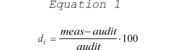
where meas is the concentration indicated by the PQAO's instrument and audit is the audit concentration of the standard used in the QC check being measured.
4.1.2 Precision Estimate. The precision estimate is used to assess the one-point QC checks for SO2, NO2, O3, or CO described in section 3.1.1 of this appendix. The precision estimator is the coefficient of variation upper bound and is calculated using equation 2 of this section:
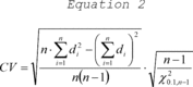
where n is the number of single point checks being aggregated; X 20.1,n-1 is the 10th percentile of a chi-squared distribution with n-1 degrees of freedom.
4.1.3 Bias Estimate. The bias estimate is calculated using the one-point QC checks for SO2, NO2, O3, or CO described in section 3.1.1 of this appendix. The bias estimator is an upper bound on the mean absolute value of the percent differences as described in equation 3 of this section:
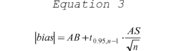
where n is the number of single point checks being aggregated; t0.95,n-1 is the 95th quantile of a t-distribution with n-1 degrees of freedom; the quantity AB is the mean of the absolute values of the di ′ s and is calculated using equation 4 of this section:

and the quantity AS is the standard deviation of the absolute value of the di ′ s and is calculated using equation 5 of this section:

4.1.3.1 Assigning a sign (positive/negative) to the bias estimate. Since the bias statistic as calculated in equation 3 of this appendix uses absolute values, it does not have a tendency (negative or positive bias) associated with it. A sign will be designated by rank ordering the percent differences of the QC check samples from a given site for a particular assessment interval.
4.1.3.2 Calculate the 25th and 75th percentiles of the percent differences for each site. The absolute bias upper bound should be flagged as positive if both percentiles are positive and negative if both percentiles are negative. The absolute bias upper bound would not be flagged if the 25th and 75th percentiles are of different signs.
4.2 Statistics for the Assessment of PM10, PM2.5, and Pb.
4.2.1 Collocated Quality Control Sampler Precision Estimate for PM10, PM2.5, and Pb . Precision is estimated via duplicate measurements from collocated samplers. It is recommended that the precision be aggregated at the PQAO level quarterly, annually, and at the 3-year level. The data pair would only be considered valid if both concentrations are greater than or equal to the minimum values specified in section 4(c) of this appendix. For each collocated data pair, calculate ti, using equation 6 to this appendix:
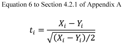
Where Xi is the concentration from the primary sampler and Yi is the concentration value from the audit sampler. The coefficient of variation upper bound is calculated using equation 7 to this appendix:
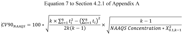
Where k is the number of valid data pairs being aggregated, and X 20.1,k-1 is the 10th percentile of a chi-squared distribution with k-1 degrees of freedom. The factor of 2 in the denominator adjusts for the fact that each ti is calculated from two values with error.
4.2.2 One-Point Flow Rate Verification Bias Estimate forPM10,PM2.5and Pb. For each one-point flow rate verification, calculate the percent difference in volume using equation 1 of this appendix where meas is the value indicated by the sampler's volume measurement and audit is the actual volume indicated by the auditing flow meter. The absolute volume bias upper bound is then calculated using equation 3, where n is the number of flow rate audits being aggregated; t0.95,n-1 is the 95th quantile of a t-distribution with n-1 degrees of freedom, the quantity AB is the mean of the absolute values of the di′s and is calculated using equation 4 of this appendix, and the quantity AS in equation 3 of this appendix is the standard deviation of the absolute values if the di′s and is calculated using equation 5 of this appendix.
4.2.3 Semi-Annual Flow Rate Audit Bias Estimate forPM10,PM2.5and Pb. Use the same procedure described in section 4.2.2 for the evaluation of flow rate audits.
4.2.4 Performance Evaluation Programs Bias Estimate for Pb. The Pb bias estimate is calculated using the paired routine and the PEP monitor as described in section 3.4.7. Use the same procedures as described in section 4.1.3 of this appendix.
4.2.5 Performance Evaluation Programs Bias Estimate for PM2.5 . The bias estimate is calculated using the PEP audits described in section 3.2.4. of this appendix. The bias estimator is based on, s i , the absolute difference in concentrations divided by the square root of the PEP concentration.
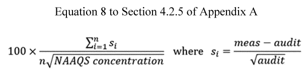
4.2.6 PbAnalysis Audit Bias Estimate. The bias estimate is calculated using the analysis audit data described in section 3.4.6. Use the same bias estimate procedure as described in section 4.1.3 of this appendix.
5. Reporting Requirements
5.1 Reporting Requirements. For each pollutant, prepare a list of all monitoring sites and their AQS site identification codes in each PQAO and submit the list to the appropriate EPA Regional Office, with a copy to AQS. Whenever there is a change in this list of monitoring sites in a PQAO, report this change to the EPA Regional Office and to AQS.
5.1.1 Quarterly Reports. For each quarter, each PQAO shall report to AQS directly (or via the appropriate EPA Regional Office for organizations not direct users of AQS) the results of all valid measurement quality checks it has carried out during the quarter. The quarterly reports must be submitted consistent with the data reporting requirements specified for air quality data as set forth in 40 CFR 58.16. The EPA strongly encourages early submission of the quality assurance data in order to assist the PQAOs ability to control and evaluate the quality of the ambient air data.
5.1.2 Annual Reports.
5.1.2.1 When the PQAO has certified relevant data for the calendar year, the EPA will calculate and report the measurement uncertainty for the entire calendar year.
6. References
(1) American National Standard Institute—Quality Management Systems For Environmental Information And Technology Programs—Requirements With Guidance For Use. ASQ/ANSI E4–2014. February 2014. Available from ANSI Webstore https://webstore.ansi.org/.
(2) EPA Requirements for Quality Management Plans. EPA QA/R-2. EPA/240/B-01/002. March 2001, Reissue May 2006. Office of Environmental Information, Washington DC 20460. http://www.epa.gov/quality/agency-wide-quality-system-documents.
(3) EPA Requirements for Quality Assurance Project Plans for Environmental Data Operations. EPA QA/R-5. EPA/240/B-01/003. March 2001, Reissue May 2006. Office of Environmental Information, Washington DC 20460. http://www.epa.gov/quality/agency-wide-quality-system-documents.
(4) EPA Traceability Protocol for Assay and Certification of Gaseous Calibration Standards. EPA–600/R–12/531. May, 2012. Available from U.S. Environmental Protection Agency, National Risk Management Research Laboratory, Research Triangle Park NC 27711. https://www.epa.gov/nscep.
(5) Guidance for the Data Quality Objectives Process. EPA QA/G-4. EPA/240/B-06/001. February, 2006. Office of Environmental Information, Washington DC 20460. http://www.epa.gov/quality/agency-wide-quality-system-documents.
(6) List of Designated Reference and Equivalent Methods. Available from U.S. Environmental Protection Agency, Center for Environmental Measurements and Modeling, Air Methods and Characterization Division, MD–D205–03, Research Triangle Park, NC 27711. https://www.epa.gov/amtic/air-monitoring-methods-criteria-pollutants.
(7) Transfer Standards for the Calibration of Ambient Air Monitoring Analyzers for Ozone. EPA–454/B–13–004 U.S. Environmental Protection Agency, Research Triangle Park, NC 27711, October, 2013. https://www.epa.gov/sites/default/files/2020-09/documents/ozonetransferstandardguidance.pdf.
(8) Paur, R.J. and F.F. McElroy. Technical Assistance Document for the Calibration of Ambient Ozone Monitors. EPA-600/4-79-057. U.S. Environmental Protection Agency, Research Triangle Park, NC 27711, September, 1979. http://www.epa.gov/ttn/amtic/cpreldoc.html.
(9) Quality Assurance Handbook for Air Pollution Measurement Systems, Volume 1—A Field Guide to Environmental Quality Assurance. EPA–600/R–94/038a. April 1994. Available from U.S. Environmental Protection Agency, ORD Publications Office, Center for Environmental Research Information (CERI), 26 W. Martin Luther King Drive, Cincinnati, OH 45268. https://www.epa.gov/amtic/ambient-air-monitoring-quality-assurance#documents.
(10) Quality Assurance Handbook for Air Pollution Measurement Systems, Volume II: Ambient Air Quality Monitoring Program Quality System Development. EPA–454/B–13–003. https://www.epa.gov/amtic/ambient-air-monitoring-quality-assurance#documents.
(11) National Performance Evaluation Program Standard Operating Procedures. https://www.epa.gov/amtic/ambient-air-monitoring-quality-assurance#npep.
| Method | Assessment method | Coverage | Minimum frequency | Parameters reported | AQS assessment type |
|---|---|---|---|---|---|
| 1 Effective concentration for open path analyzers. | |||||
| 2 Corrected concentration, if applicable for open path analyzers. | |||||
| 3 Both primary and collocated sampler values are reported as raw data. | |||||
| 4 PM 2.5 is the only particulate criteria pollutant requiring collocation of continuous and manual primary monitors. | |||||
| 5 EPA's recommended maximum number of days that should exist between checks to ensure that the checks are routinely conducted over time and to limit data impacts resulting from a failed check. | |||||
| Gaseous Methods (CO, NO 2 , SO 2 , O 3): | |||||
| One-Point QC for SO 2 , NO 2 , O 3 , CO | Response check at concentration 0.005–0.08 ppm SO 2 , NO 2 , O 3 , and 0.5 and 5 ppm CO | Each analyzer | Once per 2 weeks 5 | Audit concentration 1 and measured concentration. 2 | One-Point QC. |
| Annual performance evaluation for SO 2 , NO 2 , O 3 , CO | See section 3.1.2 of this appendix | Each analyzer | Once per year | Audit concentration 1 and measured concentration 2 for each level | Annual PE. |
| NPAP for SO 2 , NO 2 , O 3 , CO | Independent Audit | 20% of sites each year | Once per year | Audit concentration 1 and measured concentration 2 for each level | NPAP. |
| Particulate Methods: | |||||
| Continuous 4 method—collocated quality control sampling PM 2.5 | Collocated samplers | 15% | 1-in-12 days | Primary sampler concentration and duplicate sampler concentration. 3 | No Transaction reported as raw data. |
| Manual method—collocated quality control sampling PM 10 , PM 2.5 , Pb-TSP, Pb-PM 10 | Collocated samplers | 15% | 1-in-12 days | Primary sampler concentration and duplicate sampler concentration. 3 | No Transaction reported as raw data. |
| Flow rate verification PM 10 (low Vol) PM 2.5 , Pb-PM 10 | Check of sampler flow rate | Each sampler | Once every month 5 | Audit flow rate and measured flow rate indicated by the sampler | Flow Rate Verification. |
| Flow rate verification PM 10 (High-Vol), Pb-TSP | Check of sampler flow rate | Each sampler | Once every quarter 5 | Audit flow rate and measured flow rate indicated by the sampler | Flow Rate Verification. |
| Semi-annual flow rate audit PM 10 , TSP, PM 10 –2.5, PM 2.5 , Pb-TSP, Pb-PM 10 | Check of sampler flow rate using independent standard | Each sampler | Once every 6 months 5 | Audit flow rate and measured flow rate indicated by the sampler | Semi Annual Flow Rate Audit. |
| Pb analysis audits Pb-TSP, Pb-PM 10 | Check of analytical system with Pb audit strips/filters | Analytical | Once each quarter 5 | Measured value and audit value (ug Pb/filter) using AQS unit code 077 | Pb Analysis Audits. |
| Performance Evaluation Program PM 2.5 | Collocated samplers | (1) 5 valid audits for primary QA orgs, with ≤5 sites (2) 8 valid audits for primary QA orgs, with >5 sites (3) All samplers in 6 years | Distributed over all 4 quarters 5 | Primary sampler concentration and performance evaluation sampler concentration | PEP. |
| Performance Evaluation Program Pb-TSP, Pb-PM 10 | Collocated samplers | (1) 1 valid audit and 4 collocated samples for primary QA orgs, with ≤5 sites (2) 2 valid audits and 6 collocated samples for primary QA orgs with >5 sites | Distributed over all 4 quarters 5 | Primary sampler concentration and performance evaluation sampler concentration. Primary sampler concentration and duplicate sampler concentration | PEP. |
| Primary sampler method designation | Total No. of monitors | Total No. of collocated | No. of
collocated with FRM | No. of
collocated with same method designation as primary |
|---|---|---|---|---|
| FRM | 20 | 3 | 3 | 3 |
| FEM (A) | 20 | 3 | 2 | 1 |
| FEM (B) | 2 | 1 | 1 | 0 |
| FEM (C) | 12 | 2 | 1 | 1 |
Appendix B to Part 58 - Quality Assurance Requirements for Prevention of Significant Deterioration (PSD) Air Monitoring
1. General Information
2. Quality System Requirements
3. Measurement Quality Check Requirements
4. Calculations for Data Quality Assessments
5. Reporting Requirements
6. References
1. General Information
1.1 Applicability.
(a) This appendix specifies the minimum quality assurance requirements for the control and assessment of the quality of the ambient air monitoring data submitted to a PSD reviewing authority or the EPA by an organization operating an air monitoring station, or network of stations, operated in order to comply with Part 51 New Source Review - Prevention of Significant Deterioration (PSD). Such organizations are encouraged to develop and maintain quality assurance programs more extensive than the required minimum. Additional guidance for the requirements reflected in this appendix can be found in the “Quality Assurance Handbook for Air Pollution Measurement Systems,” Volume II (Ambient Air) and “Quality Assurance Handbook for Air Pollution Measurement Systems,” Volume IV (Meteorological Measurements) and at a national level in references 1, 2, and 3 of this appendix.
(b) It is not assumed that data generated for PSD under this appendix will be used in making NAAQS decisions. However, if all the requirements in this appendix are followed (including the NPEP programs) and reported to AQS, with review and concurrence from the EPA region, data may be used for NAAQS decisions. With the exception of the NPEP programs (NPAP, PM2.5 PEP, Pb-PEP), for which implementation is at the discretion of the PSD reviewing authority, all other quality assurance and quality control requirements found in the appendix must be met.
1.2 PSD Primary Quality Assurance Organization (PQAO). A PSD PQAO is defined as a monitoring organization or a coordinated aggregation of such organizations that is responsible for a set of stations within one PSD reviewing authority that monitors the same pollutant and for which data quality assessments will be pooled. Each criteria pollutant sampler/monitor must be associated with only one PSD PQAO.
1.2.1 Each PSD PQAO shall be defined such that measurement uncertainty among all stations in the organization can be expected to be reasonably homogeneous, as a result of common factors. A PSD PQAO must be associated with only one PSD reviewing authority. Common factors that should be considered in defining PSD PQAOs include:
(a) Operation by a common team of field operators according to a common set of procedures;
(b) Use of a common QAPP and/or standard operating procedures;
(c) Common calibration facilities and standards;
(d) Oversight by a common quality assurance organization; and
(e) Support by a common management organization or laboratory.
1.2.2 PSD monitoring organizations having difficulty describing its PQAO or in assigning specific monitors to a PSD PQAO should consult with the PSD reviewing authority. Any consolidation of PSD PQAOs shall be subject to final approval by the PSD reviewing authority.
1.2.3 Each PSD PQAO is required to implement a quality system that provides sufficient information to assess the quality of the monitoring data. The quality system must, at a minimum, include the specific requirements described in this appendix. Failure to conduct or pass a required check or procedure, or a series of required checks or procedures, does not by itself invalidate data for regulatory decision making. Rather, PSD PQAOs and the PSD reviewing authority shall use the checks and procedures required in this appendix in combination with other data quality information, reports, and similar documentation that demonstrate overall compliance with parts 51, 52 and 58 of this chapter. Accordingly, the PSD reviewing authority shall use a “weight of evidence” approach when determining the suitability of data for regulatory decisions. The PSD reviewing authority reserves the authority to use or not use monitoring data submitted by a PSD monitoring organization when making regulatory decisions based on the PSD reviewing authority's assessment of the quality of the data. Generally, consensus built validation templates or validation criteria already approved in quality assurance project plans (QAPPs) should be used as the basis for the weight of evidence approach.
1.3 Definitions.
(a) Measurement Uncertainty. A term used to describe deviations from a true concentration or estimate that are related to the measurement process and not to spatial or temporal population attributes of the air being measured.
(b) Precision. A measurement of mutual agreement among individual measurements of the same property usually under prescribed similar conditions, expressed generally in terms of the standard deviation.
(c) Bias. The systematic or persistent distortion of a measurement process which causes errors in one direction.
(d) Accuracy. The degree of agreement between an observed value and an accepted reference value. Accuracy includes a combination of random error (imprecision) and systematic error (bias) components which are due to sampling and analytical operations.
(e) Completeness. A measure of the amount of valid data obtained from a measurement system compared to the amount that was expected to be obtained under correct, normal conditions.
(f) Detectability. The low critical range value of a characteristic that a method specific procedure can reliably discern.
1.4 Measurement Quality Check Reporting. The measurement quality checks described in section 3 of this appendix, are required to be submitted to the PSD reviewing authority within the same time frame as routinely-collected ambient concentration data as described in 40 CFR 58.16. The PSD reviewing authority may as well require that the measurement quality check data be reported to AQS.
1.5 Assessments and Reports. Periodic assessments and documentation of data quality are required to be reported to the PSD reviewing authority. To provide national uniformity in this assessment and reporting of data quality for all networks, specific assessment and reporting procedures are prescribed in detail in sections 3, 4, and 5 of this appendix.
2. Quality System Requirements
A quality system (reference 1 of this appendix) is the means by which an organization manages the quality of the monitoring information it produces in a systematic, organized manner. It provides a framework for planning, implementing, assessing and reporting work performed by an organization and for carrying out required quality assurance and quality control activities.
2.1 Quality Assurance Project Plans. All PSD PQAOs must develop a quality system that is described and approved in quality assurance project plans (QAPP) to ensure that the monitoring results:
(a) Meet a well-defined need, use, or purpose (reference 5 of this appendix);
(b) Provide data of adequate quality for the intended monitoring objectives;
(c) Satisfy stakeholder expectations;
(d) Comply with applicable standards specifications;
(e) Comply with statutory (and other legal) requirements; and
(f) Assure quality assurance and quality control adequacy and independence.
2.1.1 The QAPP is a formal document that describes these activities in sufficient detail and is supported by standard operating procedures. The QAPP must describe how the organization intends to control measurement uncertainty to an appropriate level in order to achieve the objectives for which the data are collected. The QAPP must be documented in accordance with EPA requirements (reference 3 of this appendix).
2.1.2 The PSD PQAO's quality system must have adequate resources both in personnel and funding to plan, implement, assess and report on the achievement of the requirements of this appendix and it's approved QAPP.
2.1.3 Incorporation of quality management plan (QMP) elements into the QAPP. The QMP describes the quality system in terms of the organizational structure, functional responsibilities of management and staff, lines of authority, and required interfaces for those planning, implementing, assessing and reporting activities involving environmental data operations (EDO). The PSD PQAOs may combine pertinent elements of the QMP into the QAPP rather than requiring the submission of both QMP and QAPP documents separately, with prior approval of the PSD reviewing authority. Additional guidance on QMPs can be found in reference 2 of this appendix.
2.2 Independence of Quality Assurance Management. The PSD PQAO must provide for a quality assurance management function for its PSD data collection operation, that aspect of the overall management system of the organization that determines and implements the quality policy defined in a PSD PQAO's QAPP. Quality management includes strategic planning, allocation of resources and other systematic planning activities (e.g., planning, implementation, assessing and reporting) pertaining to the quality system. The quality assurance management function must have sufficient technical expertise and management authority to conduct independent oversight and assure the implementation of the organization's quality system relative to the ambient air quality monitoring program and should be organizationally independent of environmental data generation activities.
2.3 Data Quality Performance Requirements.
2.3.1 Data Quality Objectives (DQOs). The DQOs, or the results of other systematic planning processes, are statements that define the appropriate type of data to collect and specify the tolerable levels of potential decision errors that will be used as a basis for establishing the quality and quantity of data needed to support air monitoring objectives (reference 5 of the appendix). The DQOs have been developed by the EPA to support attainment decisions for comparison to national ambient air quality standards (NAAQS). The PSD reviewing authority and the PSD monitoring organization will be jointly responsible for determining whether adherence to the EPA developed NAAQS DQOs specified in appendix A of this part are appropriate or if DQOs from a project-specific systematic planning process are necessary.
2.3.1.1 Measurement Uncertainty for Automated and Manual PM2.5Methods. The goal for acceptable measurement uncertainty for precision is defined as an upper 90 percent confidence limit for the coefficient of variation (CV) of 10 percent and plus or minus 10 percent for total bias.
2.3.1.2 Measurement Uncertainty for Automated Ozone Methods. The goal for acceptable measurement uncertainty is defined for precision as an upper 90 percent confidence limit for the CV of 7 percent and for bias as an upper 95 percent confidence limit for the absolute bias of 7 percent.
2.3.1.3 Measurement Uncertainty for Pb Methods. The goal for acceptable measurement uncertainty is defined for precision as an upper 90 percent confidence limit for the CV of 20 percent and for bias as an upper 95 percent confidence limit for the absolute bias of 15 percent.
2.3.1.4 Measurement Uncertainty for NO2. The goal for acceptable measurement uncertainty is defined for precision as an upper 90 percent confidence limit for the CV of 15 percent and for bias as an upper 95 percent confidence limit for the absolute bias of 15 percent.
2.3.1.5 Measurement Uncertainty for SO2. The goal for acceptable measurement uncertainty for precision is defined as an upper 90 percent confidence limit for the CV of 10 percent and for bias as an upper 95 percent confidence limit for the absolute bias of 10 percent.
2.4 National Performance Evaluation Program. Organizations operating PSD monitoring networks are required to implement the EPA's national performance evaluation program (NPEP) if the data will be used for NAAQS decisions and at the discretion of the PSD reviewing authority if PSD data are not used for NAAQS decisions. The NPEP includes the National Performance Audit Program (NPAP), the PM2.5 Performance Evaluation Program (PM2.5-PEP) and the Pb Performance Evaluation Program (Pb-PEP). The PSD QAPP shall provide for the implementation of NPEP including the provision of adequate resources for such NPEP if the data will be used for NAAQS decisions or if required by the PSD reviewing authority. Contact the PSD reviewing authority to determine the best procedure for implementing the audits which may include an audit by the PSD reviewing authority, a contractor certified for the activity, or through self-implementation which is described in sections below. A determination of which entity will be performing this audit program should be made as early as possible and during the QAPP development process. The PSD PQAOs, including contractors that plan to implement these programs on behalf of PSD PQAOs, that plan to implement these programs (self-implement) rather than use the federal programs, must meet the adequacy requirements found in the appropriate sections that follow, as well as meet the definition of independent assessment that follows.
2.4.1 Independent Assessment. An assessment performed by a qualified individual, group, or organization that is not part of the organization directly performing and accountable for the work being assessed. This auditing organization must not be involved with the generation of the routinely-collected ambient air monitoring data. An organization can conduct the performance evaluation (PE) if it can meet this definition and has a management structure that, at a minimum, will allow for the separation of its routine sampling personnel from its auditing personnel by two levels of management. In addition, the sample analysis of audit filters must be performed by a laboratory facility and laboratory equipment separate from the facilities used for routine sample analysis. Field and laboratory personnel will be required to meet the performance evaluation field and laboratory training and certification requirements. The PSD PQAO will be required to participate in the centralized field and laboratory standards certification and comparison processes to establish comparability to federally implemented programs.
2.5 Technical Systems Audit Program. The PSD reviewing authority or the EPA may conduct system audits of the ambient air monitoring programs or organizations operating PSD networks. The PSD monitoring organizations shall consult with the PSD reviewing authority to verify the schedule of any such technical systems audit. Systems audit programs are described in reference 10 of this appendix.
2.6 Gaseous and Flow Rate Audit Standards.
2.6.1 Gaseous pollutant concentration standards (permeation devices or cylinders of compressed gas) used to obtain test concentrations for CO, SO 2 , NO, and NO 2 must be EPA Protocol Gases certified in accordance with one of the procedures given in Reference 4 of this appendix.
2.6.1.1 The concentrations of EPA Protocol Gas standards used for ambient air monitoring must be certified with a 95-percent confidence interval to have an analytical uncertainty of no more than ±2.0 percent (inclusive) of the certified concentration (tag value) of the gas mixture. The uncertainty must be calculated in accordance with the statistical procedures defined in Reference 4 of this appendix.
2.6.1.2 Specialty gas producers advertising certification with the procedures provided in Reference 4 of this appendix and distributing gases as “EPA Protocol Gas” for ambient air monitoring purposes must adhere to the regulatory requirements specified in 40 CFR 75.21(g) or not use “EPA” in any form of advertising. The PSD PQAOs must provide information to the PSD reviewing authority on the specialty gas producers they use (or will use) for the duration of the PSD monitoring project. This information can be provided in the QAPP or monitoring plan but must be updated if there is a change in the specialty gas producers used.
2.6.2 Test concentrations for ozone (O3) must be obtained in accordance with the ultraviolet photometric calibration procedure specified in appendix D to Part 50, and by means of a certified NIST-traceable O3 transfer standard. Consult references 7 and 8 of this appendix for guidance on transfer standards for O3.
2.6.3 Flow rate measurements must be made by a flow measuring instrument that is NIST-traceable to an authoritative volume or other applicable standard. Guidance for certifying some types of flow-meters is provided in reference 10 of this appendix.
2.7 Primary Requirements and Guidance. Requirements and guidance documents for developing the quality system are contained in references 1 through 11 of this appendix, which also contain many suggested procedures, checks, and control specifications. Reference 10 describes specific guidance for the development of a quality system for data collected for comparison to the NAAQS. Many specific quality control checks and specifications for methods are included in the respective reference methods described in Part 50 or in the respective equivalent method descriptions available from the EPA (reference 6 of this appendix). Similarly, quality control procedures related to specifically designated reference and equivalent method monitors are contained in the respective operation or instruction manuals associated with those monitors. For PSD monitoring, the use of reference and equivalent method monitors are required.
3. Measurement Quality Check Requirements
This section provides the requirements for PSD PQAOs to perform the measurement quality checks that can be used to assess data quality. Data from these checks are required to be submitted to the PSD reviewing authority within the same time frame as routinely-collected ambient concentration data as described in 40 CFR 58.16. Table B-1 of this appendix provides a summary of the types and frequency of the measurement quality checks that are described in this section. Reporting these results to AQS may be required by the PSD reviewing authority.
3.1 Gaseous monitors of SO2, NO2, O3, and CO.
3.1.1 One-Point Quality Control (QC) Check for SO2,NO2, O3, andCO. (a) A one-point QC check must be performed at least once every 2 weeks on each automated monitor used to measure SO2, NO2, O3 and CO. With the advent of automated calibration systems, more frequent checking is strongly encouraged and may be required by the PSD reviewing authority. See Reference 10 of this appendix for guidance on the review procedure. The QC check is made by challenging the monitor with a QC check gas of known concentration (effective concentration for open path monitors) between the prescribed range of 0.005 and 0.08 parts per million (ppm) for SO2, NO2, and O3, and between the prescribed range of 0.5 and 5 ppm for CO monitors. The QC check gas concentration selected within the prescribed range should be related to monitoring objectives for the monitor. If monitoring for trace level monitoring, the QC check concentration should be selected to represent the mean or median concentrations at the site. If the mean or median concentrations at trace gas sites are below the MDL of the instrument the agency can select the lowest concentration in the prescribed range that can be practically achieved. If the mean or median concentrations at trace gas sites are above the prescribed range the agency can select the highest concentration in the prescribed range. The PSD monitoring organization will consult with the PSD reviewing authority on the most appropriate one-point QC concentration based on the objectives of the monitoring activity. An additional QC check point is encouraged for those organizations that may have occasional high values or would like to confirm the monitors' linearity at the higher end of the operational range or around NAAQS concentrations. If monitoring for NAAQS decisions the QC concentration can be selected at a higher concentration within the prescribed range but should also consider precision points around mean or median concentrations.
(b) Point analyzers must operate in their normal sampling mode during the QC check and the test atmosphere must pass through all filters, scrubbers, conditioners and other components used during normal ambient sampling and as much of the ambient air inlet system as is practicable. The QC check must be conducted before any calibration or adjustment to the monitor.
(c) Open-path monitors are tested by inserting a test cell containing a QC check gas concentration into the optical measurement beam of the instrument. If possible, the normally used transmitter, receiver, and as appropriate, reflecting devices should be used during the test and the normal monitoring configuration of the instrument should be altered as little as possible to accommodate the test cell for the test. However, if permitted by the associated operation or instruction manual, an alternate local light source or an alternate optical path that does not include the normal atmospheric monitoring path may be used. The actual concentration of the QC check gas in the test cell must be selected to produce an effective concentration in the range specified earlier in this section. Generally, the QC test concentration measurement will be the sum of the atmospheric pollutant concentration and the QC test concentration. As such, the result must be corrected to remove the atmospheric concentration contribution. The corrected concentration is obtained by subtracting the average of the atmospheric concentrations measured by the open path instrument under test immediately before and immediately after the QC test from the QC check gas concentration measurement. If the difference between these before and after measurements is greater than 20 percent of the effective concentration of the test gas, discard the test result and repeat the test. If possible, open path monitors should be tested during periods when the atmospheric pollutant concentrations are relatively low and steady.
(d) Report the audit concentration of the QC gas and the corresponding measured concentration indicated by the monitor. The percent differences between these concentrations are used to assess the precision and bias of the monitoring data as described in sections 4.1.2 (precision) and 4.1.3 (bias) of this appendix.
3.1.2 Quarterly performance evaluation for SO2,NO2, O3, or CO. Evaluate each primary monitor each monitoring quarter (or 90 day frequency) during which monitors are operated or a least once (if operated for less than one quarter). The quarterly performance evaluation (quarterly PE) must be performed by a qualified individual, group, or organization that is not part of the organization directly performing and accountable for the work being assessed. The person or entity performing the quarterly PE must not be involved with the generation of the routinely-collected ambient air monitoring data. A PSD monitoring organization can conduct the quarterly PE itself if it can meet this definition and has a management structure that, at a minimum, will allow for the separation of its routine sampling personnel from its auditing personnel by two levels of management. The quarterly PE also requires a set of equipment and standards independent from those used for routine calibrations or zero, span or precision checks.
3.1.2.1 The evaluation is made by challenging the monitor with audit gas standards of known concentration from at least three audit levels. One point must be within two to three times the method detection limit of the instruments within the PQAOs network, the second point will be less than or equal to the 99th percentile of the data at the site or the network of sites in the PQAO or the next highest audit concentration level. The third point can be around the primary NAAQS or the highest 3-year concentration at the site or the network of sites in the PQAO. An additional 4th level is encouraged for those PSD organizations that would like to confirm the monitor's linearity at the higher end of the operational range. In rare circumstances, there may be sites measuring concentrations above audit level 10. These sites should be identified to the PSD reviewing authority.
| Audit level | Concentration range, ppm | |||
|---|---|---|---|---|
| O3 | SO2 | NO2 | CO | |
| 1 | 0.004-0.0059 | 0.0003-0.0029 | 0.0003-0.0029 | 0.020-0.059 |
| 2 | 0.006-0.019 | 0.0030-0.0049 | 0.0030-0.0049 | 0.060-0.199 |
| 3 | 0.020-0.039 | 0.0050-0.0079 | 0.0050-0.0079 | 0.200-0.899 |
| 4 | 0.040-0.069 | 0.0080-0.0199 | 0.0080-0.0199 | 0.900-2.999 |
| 5 | 0.070-0.089 | 0.0200-0.0499 | 0.0200-0.0499 | 3.000-7.999 |
| 6 | 0.090-0.119 | 0.0500-0.0999 | 0.0500-0.0999 | 8.000-15.999 |
| 7 | 0.120-0.139 | 0.1000-0.1499 | 0.1000-0.2999 | 16.000-30.999 |
| 8 | 0.140-0.169 | 0.1500-0.2599 | 0.3000-0.4999 | 31.000-39.999 |
| 9 | 0.170-0.189 | 0.2600-0.7999 | 0.5000-0.7999 | 40.000-49.999 |
| 10 | 0.190-0.259 | 0.8000-1.000 | 0.8000-1.000 | 50.000-60.000 |
3.1.2.2 [Reserved]
3.1.2.3 The standards from which audit gas test concentrations are obtained must meet the specifications of section 2.6.1 of this appendix.
3.1.2.4 For point analyzers, the evaluation shall be carried out by allowing the monitor to analyze the audit gas test atmosphere in its normal sampling mode such that the test atmosphere passes through all filters, scrubbers, conditioners, and other sample inlet components used during normal ambient sampling and as much of the ambient air inlet system as is practicable.
3.1.2.5 Open-path monitors are evaluated by inserting a test cell containing the various audit gas concentrations into the optical measurement beam of the instrument. If possible, the normally used transmitter, receiver, and, as appropriate, reflecting devices should be used during the evaluation, and the normal monitoring configuration of the instrument should be modified as little as possible to accommodate the test cell for the evaluation. However, if permitted by the associated operation or instruction manual, an alternate local light source or an alternate optical path that does not include the normal atmospheric monitoring path may be used. The actual concentrations of the audit gas in the test cell must be selected to produce effective concentrations in the evaluation level ranges specified in this section of this appendix. Generally, each evaluation concentration measurement result will be the sum of the atmospheric pollutant concentration and the evaluation test concentration. As such, the result must be corrected to remove the atmospheric concentration contribution. The corrected concentration is obtained by subtracting the average of the atmospheric concentrations measured by the open-path instrument under test immediately before and immediately after the evaluation test (or preferably before and after each evaluation concentration level) from the evaluation concentration measurement. If the difference between the before and after measurements is greater than 20 percent of the effective concentration of the test gas standard, discard the test result for that concentration level and repeat the test for that level. If possible, open-path monitors should be evaluated during periods when the atmospheric pollutant concentrations are relatively low and steady. Also, if the open-path instrument is not installed in a permanent manner, the monitoring path length must be reverified to be within ±3 percent to validate the evaluation, since the monitoring path length is critical to the determination of the effective concentration.
3.1.2.6 Report both the evaluation concentrations (effective concentrations for open-path monitors) of the audit gases and the corresponding measured concentration (corrected concentrations, if applicable, for open-path monitors) indicated or produced by the monitor being tested. The percent differences between these concentrations are used to assess the quality of the monitoring data as described in section 4.1.1 of this appendix.
3.1.3 National Performance Audit Program (NPAP). As stated in sections 1.1 and 2.4, PSD monitoring networks may be subject to the NPEP, which includes the NPAP. The NPAP is a performance evaluation which is a type of audit where quantitative data are collected independently in order to evaluate the proficiency of an analyst, monitoring instrument and laboratory. Due to the implementation approach used in this program, NPAP provides for a national independent assessment of performance with a consistent level of data quality. The NPAP should not be confused with the quarterly PE program described in section 3.1.2. The PSD organizations shall consult with the PSD reviewing authority or the EPA regarding whether the implementation of NPAP is required and the implementation options available. Details of the EPA NPAP can be found in reference 11 of this appendix. The program requirements include:
3.1.3.1 Performing audits on 100 percent of monitors and sites each year including monitors and sites that may be operated for less than 1 year. The PSD reviewing authority has the authority to require more frequent audits at sites they consider to be high priority.
3.1.3.2 Developing a delivery system that will allow for the audit concentration gasses to be introduced at the probe inlet where logistically feasible.
3.1.3.3 Using audit gases that are verified against the NIST standard reference methods or special review procedures and validated per the certification periods specified in Reference 4 of this appendix (EPA Traceability Protocol for Assay and Certification of Gaseous Calibration Standards) for CO, SO 2 , and NO 2 and using O 3 analyzers that are verified quarterly against a standard reference photometer.
3.1.3.4 The PSD PQAO may elect to self-implement NPAP. In these cases, the PSD reviewing authority will work with those PSD PQAOs to establish training and other technical requirements to establish comparability to federally implemented programs. In addition to meeting the requirements in sections 3.1.1.3 through 3.1.3.3, the PSD PQAO must:
(a) Ensure that the PSD audit system is equivalent to the EPA NPAP audit system and is an entirely separate set of equipment and standards from the equipment used for quarterly performance evaluations. If this system does not generate and analyze the audit concentrations, as the EPA NPAP system does, its equivalence to the EPA NPAP system must be proven to be as accurate under a full range of appropriate and varying conditions as described in section 3.1.3.6.
(b) Perform a whole system check by having the PSD audit system tested at an independent and qualified EPA lab, or equivalent.
(c) Evaluate the system with the EPA NPAP program through collocated auditing at an acceptable number of sites each year (at least one for a PSD network of five or less sites; at least two for a network with more than five sites).
(d) Incorporate the NPAP into the PSD PQAO's QAPP.
(e) Be subject to review by independent, EPA-trained personnel.
(f) Participate in initial and update training/certification sessions.
3.2 PM2.5.
3.2.1 Flow Rate Verification for PM2.5. A one-point flow rate verification check must be performed at least once every month (each verification minimally separated by 14 days) on each monitor used to measure PM2.5. The verification is made by checking the operational flow rate of the monitor. If the verification is made in conjunction with a flow rate adjustment, it must be made prior to such flow rate adjustment. For the standard procedure, use a flow rate transfer standard certified in accordance with section 2.6 of this appendix to check the monitor's normal flow rate. Care should be used in selecting and using the flow rate measurement device such that it does not alter the normal operating flow rate of the monitor. Flow rate verification results are to be reported to the PSD reviewing authority quarterly as described in section 5.1. Reporting these results to AQS is encouraged. The percent differences between the audit and measured flow rates are used to assess the bias of the monitoring data as described in section 4.2.2 of this appendix (using flow rates in lieu of concentrations).
3.2.2 Semi-Annual Flow Rate Audit for PM2.5. Every 6 months, audit the flow rate of the PM2.5 particulate monitors. For short-term monitoring operations (those less than 1 year), the flow rate audits must occur at start up, at the midpoint, and near the completion of the monitoring project. The audit must be conducted by a trained technician other than the routine site operator. The audit is made by measuring the monitor's normal operating flow rate using a flow rate transfer standard certified in accordance with section 2.6 of this appendix. The flow rate standard used for auditing must not be the same flow rate standard used for verifications or to calibrate the monitor. However, both the calibration standard and the audit standard may be referenced to the same primary flow rate or volume standard. Care must be taken in auditing the flow rate to be certain that the flow measurement device does not alter the normal operating flow rate of the monitor. Report the audit flow rate of the transfer standard and the corresponding flow rate measured by the monitor. The percent differences between these flow rates are used to evaluate monitor performance.
3.2.3 Collocated Sampling Procedures for PM2.5. A PSD PQAO must have at least one collocated monitor for each PSD monitoring network.
3.2.3.1 For each pair of collocated monitors, designate one sampler as the primary monitor whose concentrations will be used to report air quality for the site, and designate the other as the QC monitor. There can be only one primary monitor at a monitoring site for a given time period.
(a) If the primary monitor is a FRM, then the quality control monitor must be a FRM of the same method designation.
(b) If the primary monitor is a FEM, then the quality control monitor must be a FRM unless the PSD PQAO submits a waiver for this requirement, provides a specific reason why a FRM cannot be implemented, and the waiver is approved by the PSD reviewing authority. If the waiver is approved, then the quality control monitor must be the same method designation as the primary FEM monitor.
3.2.3.2 In addition, the collocated monitors should be deployed according to the following protocol:
(a) The collocated quality control monitor(s) should be deployed at sites with the highest predicted daily PM2.5 concentrations in the network. If the highest PM2.5 concentration site is impractical for collocation purposes, alternative sites approved by the PSD reviewing authority may be selected. If additional collocated sites are necessary, the PSD PQAO and the PSD reviewing authority should determine the appropriate location(s) based on data needs.
(b) The two collocated monitors must be within 4 meters of each other and at least 2 meters apart for flow rates greater than 200 liters/min or at least 1 meter apart for samplers having flow rates less than 200 liters/min to preclude airflow interference. A waiver allowing up to 10 meters horizontal distance and up to 3 meters vertical distance (inlet to inlet) between a primary and collocated quality control monitor may be approved by the PSD reviewing authority for sites at a neighborhood or larger scale of representation. This waiver may be approved during the QAPP review and approval process. Sampling and analytical methodologies must be the consistently implemented for both collocated samplers and for all other samplers in the network.
(c) Sample the collocated quality control monitor on a 6-day schedule for sites not requiring daily monitoring and on a 3-day schedule for any site requiring daily monitoring. Report the measurements from both primary and collocated quality control monitors at each collocated sampling site. The calculations for evaluating precision between the two collocated monitors are described in section 4.2.1 of this appendix.
3.2.4 PM2.5 Performance Evaluation Program (PEP) Procedures. The PEP is an independent assessment used to estimate total measurement system bias. These evaluations will be performed under the NPEP as described in section 2.4 of this appendix or a comparable program. Performance evaluations will be performed annually within each PQAO. For PQAOs with less than or equal to five monitoring sites, five valid performance evaluation audits must be collected and reported each year. For PQAOs with greater than five monitoring sites, eight valid performance evaluation audits must be collected and reported each year. A valid performance evaluation audit means that both the primary monitor and PEP audit concentrations are valid and equal to or greater than 2 µg/m3. Siting of the PEP monitor must be consistent with section 3.2.3.4(c) of this appendix. However, any horizontal distance greater than 4 meters and any vertical distance greater than one meter must be reported to the EPA regional PEP coordinator. Additionally for every monitor designated as a primary monitor, a primary quality assurance organization must:
3.2.4.1 Have each method designation evaluated each year; and,
3.2.4.2 Have all FRM and FEM samplers subject to a PEP audit at least once every 6 years, which equates to approximately 15 percent of the monitoring sites audited each year.
3.2.4.3 Additional information concerning the PEP is contained in Reference 10 of this appendix. The calculations for evaluating bias between the primary monitor and the performance evaluation monitor for PM 2.5 are described in section 4.2.5 of this appendix.
3.3 PM10.
3.3.1 Flow Rate Verification for PM10. A one-point flow rate verification check must be performed at least once every month (each verification minimally separated by 14 days) on each monitor used to measure PM10. The verification is made by checking the operational flow rate of the monitor. If the verification is made in conjunction with a flow rate adjustment, it must be made prior to such flow rate adjustment. For the standard procedure, use a flow rate transfer standard certified in accordance with section 2.6 of this appendix to check the monitor's normal flow rate. Care should be taken in selecting and using the flow rate measurement device such that it does not alter the normal operating flow rate of the monitor. The percent differences between the audit and measured flow rates are used to assess the bias of the monitoring data as described in section 4.2.2 of this appendix (using flow rates in lieu of concentrations).
3.3.2 Semi-Annual Flow Rate Audit for PM10. Every 6 months, audit the flow rate of the PM10 particulate monitors. For short-term monitoring operations (those less than 1 year), the flow rate audits must occur at start up, at the midpoint, and near the completion of the monitoring project. Where possible, the EPA strongly encourages more frequent auditing. The audit must be conducted by a trained technician other than the routine site operator. The audit is made by measuring the monitor's normal operating flow rate using a flow rate transfer standard certified in accordance with section 2.6 of this appendix. The flow rate standard used for auditing must not be the same flow rate standard used for verifications or to calibrate the monitor. However, both the calibration standard and the audit standard may be referenced to the same primary flow rate or volume standard. Care must be taken in auditing the flow rate to be certain that the flow measurement device does not alter the normal operating flow rate of the monitor. Report the audit flow rate of the transfer standard and the corresponding flow rate measured by the monitor. The percent differences between these flow rates are used to evaluate monitor performance
3.3.3 Collocated Sampling Procedures for Manual PM10. A PSD PQAO must have at least one collocated monitor for each PSD monitoring network.
3.3.3.1 For each pair of collocated monitors, designate one sampler as the primary monitor whose concentrations will be used to report air quality for the site, and designate the other as the quality control monitor.
3.3.3.2 In addition, the collocated monitors should be deployed according to the following protocol:
(a) The collocated quality control monitor(s) should be deployed at sites with the highest predicted daily PM10 concentrations in the network. If the highest PM10 concentration site is impractical for collocation purposes, alternative sites approved by the PSD reviewing authority may be selected.
(b) The two collocated monitors must be within 4 meters of each other and at least 2 meters apart for flow rates greater than 200 liters/min or at least 1 meter apart for samplers having flow rates less than 200 liters/min to preclude airflow interference. A waiver allowing up to 10 meters horizontal distance and up to 3 meters vertical distance (inlet to inlet) between a primary and collocated sampler may be approved by the PSD reviewing authority for sites at a neighborhood or larger scale of representation. This waiver may be approved during the QAPP review and approval process. Sampling and analytical methodologies must be the consistently implemented for both collocated samplers and for all other samplers in the network.
(c) Sample the collocated quality control monitor on a 6-day schedule or 3-day schedule for any site requiring daily monitoring. Report the measurements from both primary and collocated quality control monitors at each collocated sampling site. The calculations for evaluating precision between the two collocated monitors are described in section 4.2.1 of this appendix.
(d) In determining the number of collocated sites required for PM10, PSD monitoring networks for Pb-PM10 should be treated independently from networks for particulate matter (PM), even though the separate networks may share one or more common samplers. However, a single quality control monitor that meets the collocation requirements for Pb-PM10 and PM10 may serve as a collocated quality control monitor for both networks. Extreme care must be taken if using the filter from a quality control monitor for both PM10 and Pb analysis. PM10 filter weighing should occur prior to any Pb analysis.
3.4 Pb.
3.4.1 Flow Rate Verification for Pb. A one-point flow rate verification check must be performed at least once every month (each verification minimally separated by 14 days) on each monitor used to measure Pb. The verification is made by checking the operational flow rate of the monitor. If the verification is made in conjunction with a flow rate adjustment, it must be made prior to such flow rate adjustment. Use a flow rate transfer standard certified in accordance with section 2.6 of this appendix to check the monitor's normal flow rate. Care should be taken in selecting and using the flow rate measurement device such that it does not alter the normal operating flow rate of the monitor. The percent differences between the audit and measured flow rates are used to assess the bias of the monitoring data as described in section 4.2.2 of this appendix (using flow rates in lieu of concentrations).
3.4.2 Semi-Annual Flow Rate Audit for Pb. Every 6 months, audit the flow rate of the Pb particulate monitors. For short-term monitoring operations (those less than 1 year), the flow rate audits must occur at start up, at the midpoint, and near the completion of the monitoring project. Where possible, the EPA strongly encourages more frequent auditing. The audit must be conducted by a trained technician other than the routine site operator. The audit is made by measuring the monitor's normal operating flow rate using a flow rate transfer standard certified in accordance with section 2.6 of this appendix. The flow rate standard used for auditing must not be the same flow rate standard used to in verifications or to calibrate the monitor. However, both the calibration standard and the audit standard may be referenced to the same primary flow rate or volume standard. Great care must be taken in auditing the flow rate to be certain that the flow measurement device does not alter the normal operating flow rate of the monitor. Report the audit flow rate of the transfer standard and the corresponding flow rate measured by the monitor. The percent differences between these flow rates are used to evaluate monitor performance.
3.4.3 Collocated Sampling for Pb. A PSD PQAO must have at least one collocated monitor for each PSD monitoring network.
3.4.3.1 For each pair of collocated monitors, designate one sampler as the primary monitor whose concentrations will be used to report air quality for the site, and designate the other as the quality control monitor.
3.4.3.2 In addition, the collocated monitors should be deployed according to the following protocol:
(a) The collocated quality control monitor(s) should be deployed at sites with the highest predicted daily Pb concentrations in the network. If the highest Pb concentration site is impractical for collocation purposes, alternative sites approved by the PSD reviewing authority may be selected.
(b) The two collocated monitors must be within 4 meters of each other and at least 2 meters apart for flow rates greater than 200 liters/min or at least 1 meter apart for samplers having flow rates less than 200 liters/min to preclude airflow interference. A waiver allowing up to 10 meters horizontal distance and up to 3 meters vertical distance (inlet to inlet) between a primary and collocated sampler may be approved by the PSD reviewing authority for sites at a neighborhood or larger scale of representation. This waiver may be approved during the QAPP review and approval process. Sampling and analytical methodologies must be the consistently implemented for both collocated samplers and all other samplers in the network.
(c) Sample the collocated quality control monitor on a 6-day schedule if daily monitoring is not required or 3-day schedule for any site requiring daily monitoring. Report the measurements from both primary and collocated quality control monitors at each collocated sampling site. The calculations for evaluating precision between the two collocated monitors are described in section 4.2.1 of this appendix.
(d) In determining the number of collocated sites required for Pb-PM10, PSD monitoring networks for PM10 should be treated independently from networks for Pb-PM10, even though the separate networks may share one or more common samplers. However, a single quality control monitor that meets the collocation requirements for Pb-PM10 and PM10 may serve as a collocated quality control monitor for both networks. Extreme care must be taken if using a using the filter from a quality control monitor for both PM10 and Pb analysis. The PM10 filter weighing should occur prior to any Pb analysis.
3.4.4 Pb Analysis Audits. Each calendar quarter, audit the Pb reference or equivalent method analytical procedure using filters containing a known quantity of Pb. These audit filters are prepared by depositing a Pb standard on unexposed filters and allowing them to dry thoroughly. The audit samples must be prepared using batches of reagents different from those used to calibrate the Pb analytical equipment being audited. Prepare audit samples in the following concentration ranges:
| Range | Equivalent ambient
Pb concentration, µg/m 3 |
|---|---|
| 1 | 30-100% of Pb NAAQS. |
| 2 | 200-300% of Pb NAAQS. |
(a) Audit samples must be extracted using the same extraction procedure used for exposed filters.
(b) Analyze three audit samples in each of the two ranges each quarter samples are analyzed. The audit sample analyses shall be distributed as much as possible over the entire calendar quarter.
(c) Report the audit concentrations (in µg Pb/filter or strip) and the corresponding measured concentrations (in µg Pb/filter or strip) using AQS unit code 077 (if reporting to AQS). The percent differences between the concentrations are used to calculate analytical accuracy as described in section 4.2.5 of this appendix.
3.4.5 Pb Performance Evaluation Program (PEP) Procedures. As stated in sections 1.1 and 2.4, PSD monitoring networks may be subject to the NPEP, which includes the Pb PEP. The PSD monitoring organizations shall consult with the PSD reviewing authority or the EPA regarding whether the implementation of Pb-PEP is required and the implementation options available for the Pb-PEP. The PEP is an independent assessment used to estimate total measurement system bias. Each year, one PE audit must be performed at one Pb site in each PSD PQAO network that has less than or equal to five sites and two audits for PSD PQAO networks with greater than five sites. In addition, each year, four collocated samples from PSD PQAO networks with less than or equal to five sites and six collocated samples from PSD PQAO networks with greater than five sites must be sent to an independent laboratory for analysis. The calculations for evaluating bias between the primary monitor and the PE monitor for Pb are described in section 4.2.4 of this appendix.
4. Calculations for Data Quality Assessments
(a) Calculations of measurement uncertainty are carried out by PSD PQAO according to the following procedures. The PSD PQAOs should report the data for all appropriate measurement quality checks as specified in this appendix even though they may elect to perform some or all of the calculations in this section on their own.
(b) At low concentrations, agreement between the measurements of collocated samplers, expressed as relative percent difference or percent difference, may be relatively poor. For this reason, collocated measurement pairs will be selected for use in the precision and bias calculations only when both measurements are equal to or above the following limits:
(1) Pb: 0.002 µg/m 3 (Methods approved after 3/04/2010, with exception of manual equivalent method EQLA-0813-803).
(2) Pb: 0.02 µg/m 3 (Methods approved before 3/04/2010, and manual equivalent method EQLA-0813-803).
(3) PM10 (Hi-Vol): 15 µg/m 3.
(4) PM10 (Lo-Vol): 3 µg/m 3.
(5) PM2.5: 3 µg/m 3.
(c) The PM2.5 3 µg/m 3 limit for the PM2.5−PEP may be superseded by mutual agreement between the PSD PQAO and the PSD reviewing authority as specified in section 3.2.4 of the appendix and detailed in the approved QAPP.
4.1 Statistics for the Assessment of QC Checks for SO2, NO2, O3and CO.
4.1.1 Percent Difference. Many of the measurement quality checks start with a comparison of an audit concentration or value (flow-rate) to the concentration/value measured by the monitor and use percent difference as the comparison statistic as described in equation 1 of this section. For each single point check, calculate the percent difference, di, as follows:
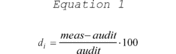
where meas is the concentration indicated by the PQAO's instrument and audit is the audit concentration of the standard used in the QC check being measured.
4.1.2 Precision Estimate. The precision estimate is used to assess the one-point QC checks for SO2, NO2, O3, or CO described in section 3.1.1 of this appendix. The precision estimator is the coefficient of variation upper bound and is calculated using equation 2 of this section:
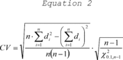
where n is the number of single point checks being aggregated; X 20.1,n-1 is the 10th percentile of a chi-squared distribution with n-1 degrees of freedom.
4.1.3 Bias Estimate. The bias estimate is calculated using the one-point QC checks for SO2, NO2, O3, or CO described in section 3.1.1 of this appendix. The bias estimator is an upper bound on the mean absolute value of the percent differences as described in equation 3 of this section:
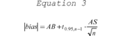
where n is the number of single point checks being aggregated; t0.95,n-1 is the 95th quantile of a t-distribution with n-1 degrees of freedom; the quantity AB is the mean of the absolute values of the di′s and is calculated using equation 4 of this section:

and the quantity AS is the standard deviation of the absolute value of the di′s and is calculated using equation 5 of this section:
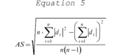
4.1.3.1 Assigning a sign (positive/negative) to the bias estimate. Since the bias statistic as calculated in equation 3 of this appendix uses absolute values, it does not have a tendency (negative or positive bias) associated with it. A sign will be designated by rank ordering the percent differences of the QC check samples from a given site for a particular assessment interval.
4.1.3.2 Calculate the 25th and 75th percentiles of the percent differences for each site. The absolute bias upper bound should be flagged as positive if both percentiles are positive and negative if both percentiles are negative. The absolute bias upper bound would not be flagged if the 25th and 75th percentiles are of different signs.
4.2 Statistics for the Assessment of PM10,PM2.5, and Pb.
4.2.1 Collocated Quality Control Sampler Precision Estimate for PM10, PM2.5, and Pb . Precision is estimated via duplicate measurements from collocated samplers. It is recommended that the precision be aggregated at the PQAO level quarterly, annually, and at the 3-year level. The data pair would only be considered valid if both concentrations are greater than or equal to the minimum values specified in section 4(c) of this appendix. For each collocated data pair, calculate ti, using equation 6 to this appendix:
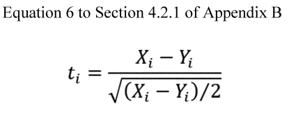
Where Xi is the concentration from the primary sampler and Yi is the concentration value from the audit sampler. The coefficient of variation upper bound is calculated using equation 7 to this appendix:
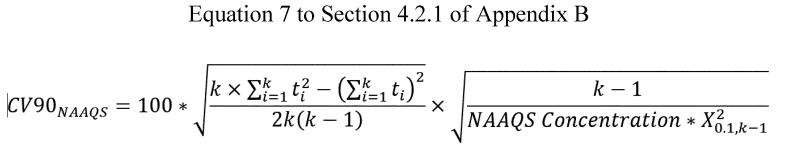
Where k is the number of valid data pairs being aggregated, and X 20.1,k-1 is the 10th percentile of a chi-squared distribution with k-1 degrees of freedom. The factor of 2 in the denominator adjusts for the fact that each ti is calculated from two values with error.
4.2.2 One-Point Flow Rate Verification Bias Estimate for PM10, PM2.5and Pb. For each one-point flow rate verification, calculate the percent difference in volume using equation 1 of this appendix where meas is the value indicated by the sampler's volume measurement and audit is the actual volume indicated by the auditing flow meter. The absolute volume bias upper bound is then calculated using equation 3, where n is the number of flow rate audits being aggregated; t0.95,n-1 is the 95th quantile of a t-distribution with n-1 degrees of freedom, the quantity AB is the mean of the absolute values of the di′s and is calculated using equation 4 of this appendix, and the quantity AS in equation 3 of this appendix is the standard deviation of the absolute values if the di′s and is calculated using equation 5 of this appendix.
4.2.3 Semi-Annual Flow Rate Audit Bias Estimate for PM10, PM2.5and Pb. Use the same procedure described in section 4.2.2 for the evaluation of flow rate audits.
4.2.4 Performance Evaluation Programs Bias Estimate for Pb. The Pb bias estimate is calculated using the paired routine and the PEP monitor as described in section 3.4.5. Use the same procedures as described in section 4.1.3 of this appendix.
4.2.5 Performance Evaluation Programs Bias Estimate for PM2.5 . The bias estimate is calculated using the PEP audits described in section 3.2.4. of this appendix. The bias estimator is based on, s i , the absolute difference in concentrations divided by the square root of the PEP concentration.
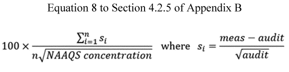
4.2.6 Pb Analysis Audit Bias Estimate. The bias estimate is calculated using the analysis audit data described in section 3.4.4. Use the same bias estimate procedure as described in section 4.1.3 of this appendix.
5. Reporting Requirements
5.1. Quarterly Reports. For each quarter, each PSD PQAO shall report to the PSD reviewing authority (and AQS if required by the PSD reviewing authority) the results of all valid measurement quality checks it has carried out during the quarter. The quarterly reports must be submitted consistent with the data reporting requirements specified for air quality data as set forth in 40 CFR 58.16 and pertain to PSD monitoring.
6. References
(1) American National Standard Institute—Quality Management Systems For Environmental Information And Technology Programs—Requirements With Guidance For Use. ASQ/ANSI E4–2014. February 2014. Available from ANSI Webstore https://webstore.ansi.org/.
(2) EPA Requirements for Quality Management Plans. EPA QA/R-2. EPA/240/B-01/002. March 2001, Reissue May 2006. Office of Environmental Information, Washington, DC 20460. http://www.epa.gov/quality/agency-wide-quality-system-documents.
(3) EPA Requirements for Quality Assurance Project Plans for Environmental Data Operations. EPA QA/R-5. EPA/240/B-01/003. March 2001, Reissue May 2006. Office of Environmental Information, Washington, DC 20460. http://www.epa.gov/quality/agency-wide-quality-system-documents.
(4) EPA Traceability Protocol for Assay and Certification of Gaseous Calibration Standards. EPA–600/R–12/531. May, 2012. Available from U.S. Environmental Protection Agency, National Risk Management Research Laboratory, Research Triangle Park NC 27711. https://www.epa.gov/nscep.
(5) Guidance for the Data Quality Objectives Process. EPA QA/G-4. EPA/240/B-06/001. February, 2006. Office of Environmental Information, Washington, DC 20460. http://www.epa.gov/quality/agency-wide-quality-system-documents.
(6) List of Designated Reference and Equivalent Methods. Available from U.S. Environmental Protection Agency, Center for Environmental Measurements and Modeling, Air Methods and Characterization Division, MD–D205–03, Research Triangle Park, NC 27711. https://www.epa.gov/amtic/air-monitoring-methods-criteria-pollutants.
(7) Transfer Standards for the Calibration of Ambient Air Monitoring Analyzers for Ozone. EPA–454/B–13–004 U.S. Environmental Protection Agency, Research Triangle Park, NC 27711, October, 2013. https://www.epa.gov/sites/default/files/2020-09/documents/ozonetransferstandardguidance.pdf.
(8) Paur, R.J. and F.F. McElroy. Technical Assistance Document for the Calibration of Ambient Ozone Monitors. EPA-600/4-79-057. U.S. Environmental Protection Agency, Research Triangle Park, NC 27711, September, 1979. http://www.epa.gov/ttn/amtic/cpreldoc.html.
(9) Quality Assurance Handbook for Air Pollution Measurement Systems, Volume 1—A Field Guide to Environmental Quality Assurance. EPA–600/R–94/038a. April 1994. Available from U.S. Environmental Protection Agency, ORD Publications Office, Center for Environmental Research Information (CERI), 26 W. Martin Luther King Drive, Cincinnati, OH 45268. https://www.epa.gov/amtic/ambient-air-monitoring-quality-assurance#documents.
(10) Quality Assurance Handbook for Air Pollution Measurement Systems, Volume II: Ambient Air Quality Monitoring Program Quality System Development. EPA–454/B–13–003. https://www.epa.gov/amtic/ambient-air-monitoring-quality-assurance#documents.
(11) National Performance Evaluation Program Standard Operating Procedures. https://www.epa.gov/amtic/ambient-air-monitoring-quality-assurance#npep.
| Method | Assessment method | Coverage | Minimum frequency | Parameters reported | AQS Assessment type |
|---|---|---|---|---|---|
| 1 Effective concentration for open path analyzers. | |||||
| 2 Corrected concentration, if applicable for open path analyzers. | |||||
| 3 NPAP, PM 2.5 , PEP, and Pb-PEP must be implemented if data is used for NAAQS decisions otherwise implementation is at PSD reviewing authority discretion. | |||||
| 4 Both primary and collocated sampler values are reported as raw data | |||||
| 5 A maximum number of days should be between these checks to ensure the checks are routinely conducted over time and to limit data impacts resulting from a failed check. | |||||
| Gaseous Methods (CO, NO 2 , SO 2 , O 3): | |||||
| One-Point QC for SO 2 , NO 2 , O 3 , CO | Response check at concentration 0.005–0.08 ppm SO 2 , NO 2 , O 3 , & 0.5 and 5 ppm CO | Each analyzer | Once per 2 weeks 5 | Audit concentration 1 and measured concentration 2 | One-Point QC. |
| Quarterly performance evaluation for SO 2 , NO 2 , O 3 , CO | See section 3.1.2 of this appendix | Each analyzer | Once per quarter 5 | Audit concentration 1 and measured concentration 2 for each level | Annual PE. |
| NPAP for SO 2 , NO 2 , O 3 , CO 3 | Independent Audit | Each primary monitor | Once per year | Audit concentration 1 and measured concentration 2 for each level | NPAP. |
| Particulate Methods: | |||||
| Collocated sampling PM 10 , PM 2.5 , Pb | Collocated samplers | 1 per PSD Network per pollutant | Every 6 days or every 3 days if daily monitoring required | Primary sampler concentration and duplicate sampler concentration 4 | No Transaction reported as raw data. |
| Flow rate verification PM 10 , PM 2.5 , Pb | Check of sampler flow rate | Each sampler | Once every month 5 | Audit flow rate and measured flow rate indicated by the sampler | Flow Rate Verification. |
| Semi-annual flow rate audit PM 10 , PM 2.5 , Pb | Check of sampler flow rate using independent standard | Each sampler | Once every 6 months or beginning, middle and end of monitoring 5 | Audit flow rate and measured flow rate indicated by the sampler | Semi Annual Flow Rate Audit. |
| Pb analysis audits Pb-TSP, Pb-PM 10 | Check of analytical system with Pb audit strips/filters | Analytical | Each quarter 5 | Measured value and audit value (ug Pb/filter) using AQS unit code 077 for parameters: 14129—Pb (TSP) LC FRM/FEM 85129—Pb (TSP) LC Non-FRM/FEM. | Pb Analysis Audits. |
| Performance Evaluation Program PM 2.53 | Collocated samplers | (1) 5 valid audits for PQAOs with <= 5 sites. (2) 8 valid audits for PQAOs with > 5 sites. (3) All samplers in 6 years | Over all 4 quarters 5 | Primary sampler concentration and performance evaluation sampler concentration | PEP. |
| Performance Evaluation Program Pb 3 | Collocated samplers | (1) 1 valid audit and 4 collocated samples for PQAOs, with <=5 sites. (2) 2 valid audits and 6 collocated samples for PQAOs with >5 sites. | Over all 4 quarters 5 | Primary sampler concentration and performance evaluation sampler concentration. Primary sampler concentration and duplicate sampler concentration | PEP. |
Appendix C to Part 58—Ambient Air Quality Monitoring Methodology
* * * *
2.0 SLAMS Ambient Air Monitoring Network
2.1 Except as otherwise provided in this appendix, a criteria pollutant monitoring method used for making NAAQS decisions at a SLAMS site must be a reference or equivalent method as defined in §50.1 of this chapter.
2.1.1 Any NO2 FRM or FEM used for making primary NAAQS decisions must be capable of providing hourly averaged concentration data.
2.2 PM 10 , PM 2.5 , or PM 10–2.5 continuous FEMs with existing valid designations may be calibrated using network data from collocated FRM and continuous FEM data under the following provisions:
2.2.1 Data to demonstrate a calibration may include valid data from State, local, or Tribal air agencies or data collected by instrument manufacturers in accordance with 40 CFR 53.35 or other data approved by the Administrator.
2.2.2 A request to update a designated methods calibration may be initiated by the instrument manufacturer of record or the EPA Administrator. State, local, Tribal, and multijusistincional organizations of these entities may work with an instrument manufacture to update a designated method calibration.
2.2.3 Requests for approval of an updated PM 10 , PM 2.5 , or PM 10–2.5 continuous FEM calibration must meet the general submittal requirements of section 2.7 of this appendix.
2.2.4 Data included in the request should represent a subset of representative locations where the method is operational. For cases with a small number of collocated FRMs and continuous FEMs sites, an updated candidate calibration may be limited to the sites where both methods are in use.
2.2.5 Data included in a candidate method updated calibration may include a subset of sites where there is a large grouping of sites in one part of the country such that the updated calibration would be representative of the country as a whole.
2.2.6 Improvements should be national in scope and ideally implemented through a firmware change.
2.2.7 The goal of a change to a methods calibration is to increase the number of sites meeting measurements quality objectives of the method as identified in section 2.3.1.1 of appendix A to this part.
2.2.8 For meeting measurement quality objectives (MQOs), the primary objective is to meet the bias goal as this statistic will likely have the most influence on improving the resultant data collected.
2.2.9 Precision data are to be included, but so long as precision data are at least as good as existing network data or meet the MQO referenced in section 2.2.8 of this appendix, no further work is necessary with precision.
2.2.10 Data available to use may include routine primary and collocated data.
2.2.11 Audit data may be useful to confirm the performance of a candidate updated calibration but should not be used as the basis of the calibration to keep the independence of the audit data.
2.2.12 Data utilized as the basis of the updated calibration may be obtained by accessing EPA's AQS database or future analogous EPA database.
2.2.13 Years of data to use in a candidate method calibration should include two recent years where we are past the certification period for the previous year's data, which is May 1 of each year.
2.2.14 Data from additional years is to be used to test an updated calibration such that the calibration is independent of the test years of interest. Data from these additional years need to minimally demonstrate that a larger number of sites are expected to meet bias MQO especially at sites near the level of the NAAQS for the PM indicator of interest.
2.2.15 Outliers may be excluded using routine outlier tests.
2.2.16 The range of data used in a calibration may include all data available or alternatively use data in the range from the lowest measured data available up to 125% of the 24-hour NAAQS for the PM indicator of interest.
2.2.17 Other improvements to a PM continuous method may be included as part of a recommended update so long as appropriate testing is conducted with input from EPA's Office of Research and Development (ORD) Reference and Equivalent (R&E) Methods Designation program.
2.2.18 EPA encourages early communication by instrument manufacturers considering an update to a PM method. Instrument companies should initiate such dialogue by contacting EPA's ORD R&E Methods Designation program. The contact information for this can be found at 40 CFR 53.4.
2.2.19 Manufacturers interested in improving instrument's performance through an updated factory calibration must submit a written modification request to EPA with supporting rationale. Because the testing requirements and acceptance criteria of any field and/or lab tests can depend upon the nature and extent of the intended modification, applicants should contact EPA's R&E Methods Designation program for guidance prior to development of the modification request.
2.3 Any manual method or analyzer purchased prior to cancellation of its reference or equivalent method designation under §53.11 or §53.16 of this chapter may be used at a SLAMS site following cancellation for a reasonable period of time to be determined by the Administrator.
2.4 [Reserved]
2.4.1 [Reserved]
2.4.2 The monitoring agency wishing to use an ARM must develop and implement appropriate quality assurance procedures for the method. Additionally, the following procedures are required for the method:
2.4.2.1 The ARM must be consistently operated throughout the network. Exceptions to a consistent operation must be approved according to section 2.8 of this appendix;
2.4.2.2 The ARM must be operated on an hourly sampling frequency capable of providing data suitable for aggregation into daily 24-hour average measurements;
2.4.2.3 The ARM must use an inlet and separation device, as needed, that are already approved in either the reference method identified in appendix L to part 50 of this chapter or under part 53 of this chapter as approved for use on a PM 2.5 reference or equivalent method. The only exceptions to this requirement are those methods that by their inherent measurement principle may not need an inlet or separation device that segregates the aerosol; and
2.4.2.4 The ARM must be capable of providing for flow audits, unless by its inherent measurement principle, measured flow is not required. These flow audits are to be performed on the frequency identified in appendix A to this part.
2.4.2.5 If data transformations are used, they must be described in the monitoring agencies Quality Assurance Project plan (or addendum to QAPP). The QAPP shall describe how often (e.g., quarterly, yearly) and under what provisions the data transformation will be updated. For example, not meeting the data quality objectives for a site over a season or year may be cause for recalculating a data transformation, but by itself would not be cause for invalidating the data. Data transformations must be applied prospectively, i.e., in real-time or near real-time, to the data output from the PM 2.5 continuous method. See reference 7 of this appendix.
2.4.3 The monitoring agency wishing to use the method must develop and implement appropriate procedures for assessing and reporting the precision and accuracy of the method comparable to the procedures set forth in appendix A of this part for designated reference and equivalent methods.
2.4.4 Assessments of data quality shall follow the same frequencies and calculations as required under section 3 of appendix A to this part with the following exceptions:
2.4.4.1 Collocation of ARM with FRM/FEM samplers must be maintained at a minimum of 30 percent of the required SLAMS sites with a minimum of 1 per network;
2.4.4.2 All collocated FRM/FEM samplers must maintain a sample frequency of at least 1 in 6 sample days;
2.4.4.3 Collocated FRM/FEM samplers shall be located at the design value site, with the required FRM/FEM samplers deployed among the largest MSA/CSA in the network, until all required FRM/FEM are deployed; and
2.4.4.4 Data from collocated FRM/FEM are to be substituted for any calendar quarter that an ARM method has incomplete data.
2.4.4.5 Collocation with an ARM under this part for purposes of determining the coefficient of variation of the method shall be conducted at a minimum of 7.5 percent of the sites with a minimum of 1 per network. This is consistent with the requirements in appendix A to this part for one-half of the required collocation of FRM/FEM (15 percent) to be collocated with the same method.
2.4.4.6 Assessments of bias with an independent audit of the total measurement system shall be conducted with the same frequency as an FEM as identified in appendix A to this part.
2.4.5 Request for approval of a candidate ARM, that is not already approved in another agency's network under this section, must meet the general submittal requirements of section 2.7 of this appendix. Requests for approval under this section when an ARM is already approved in another agency's network are to be submitted to the EPA Regional Administrator. Requests for approval under section 2.4 of this appendix must include the following requirements:
2.4.5.1 A clear and unique description of the site(s) at which the candidate ARM will be used and tested, and a description of the nature or character of the site and the particulate matter that is expected to occur there.
2.4.5.2 A detailed description of the method and the nature of the sampler or analyzer upon which it is based.
2.4.5.3 A brief statement of the reason or rationale for requesting the approval.
2.4.5.4 A detailed description of the quality assurance procedures that have been developed and that will be implemented for the method.
2.4.5.5 A detailed description of the procedures for assessing the precision and accuracy of the method that will be implemented for reporting to AQS.
2.4.5.6 Test results from the comparability tests as required in section 2.4.1 through 2.4.1.4 of this appendix.
2.4.5.7 Such further supplemental information as may be necessary or helpful to support the required statements and test results.
2.4.6 Within 120 days after receiving a request for approval of the use of an ARM at a particular site or network of sites under section 2.4 of this appendix, the Administrator will approve or disapprove the method by letter to the person or agency requesting such approval. When appropriate for methods that are already approved in another SLAMS network, the EPA Regional Administrator has approval/disapproval authority. In either instance, additional information may be requested to assist with the decision.
2.5 [Reserved]
2.6 Use of Methods With Higher, Nonconforming Ranges in Certain Geographical Areas.
2.6.1 [Reserved]
2.6.2 An analyzer may be used (indefinitely) on a range which extends to concentrations higher than two times the upper limit specified in table B-1 of part 53 of this chapter if:
2.6.2.1 The analyzer has more than one selectable range and has been designated as a reference or equivalent method on at least one of its ranges, or has been approved for use under section 2.5 (which applies to analyzers purchased before February 18, 1975);
2.6.2.2 The pollutant intended to be measured with the analyzer is likely to occur in concentrations more than two times the upper range limit specified in table B-1 of part 53 of this chapter in the geographical area in which use of the analyzer is proposed; and
2.6.2.3 The Administrator determines that the resolution of the range or ranges for which approval is sought is adequate for its intended use. For purposes of this section (2.6), “resolution” means the ability of the analyzer to detect small changes in concentration.
2.6.3 Requests for approval under section 2.6.2 of this appendix must meet the submittal requirements of section 2.7. Except as provided in section 2.7.3 of this appendix, each request must contain the information specified in section 2.7.2 in addition to the following:
2.6.3.1 The range or ranges proposed to be used;
2.6.3.2 Test data, records, calculations, and test results as specified in section 2.7.2.2 of this appendix for each range proposed to be used;
2.6.3.3 An identification and description of the geographical area in which use of the analyzer is proposed;
2.6.3.4 Data or other information demonstrating that the pollutant intended to be measured with the analyzer is likely to occur in concentrations more than two times the upper range limit specified in table B-1 of part 53 of this chapter in the geographical area in which use of the analyzer is proposed; and
2.6.3.5 Test data or other information demonstrating the resolution of each proposed range that is broader than that permitted by section 2.5 of this appendix.
2.6.4 Any person who has obtained approval of a request under this section (2.6.2) shall assure that the analyzer for which approval was obtained is used only in the geographical area identified in the request and only while operated in the range or ranges specified in the request.
2.7 Requests for Approval; Withdrawal of Approval.
2.7.1 Requests for approval under sections 2.2, 2.4, 2.6.2, or 2.8 of this appendix must be submitted to: Director, Center for Environmental Measurement and Modeling, Reference and Equivalent Methods Designation Program (MD–D205–03), U.S. Environmental Protection Agency, P.O. Box 12055, Research Triangle Park, North Carolina 27711.
2.7.2 Except as provided in section 2.7.3 of this appendix, each request must contain:
2.7.2.1 A statement identifying the analyzer (e.g., by serial number) and the method of which the analyzer is representative (e.g., by manufacturer and model number); and
2.7.2.2 Test data, records, calculations, and test results for the analyzer (or the method of which the analyzer is representative) as specified in subpart B, subpart C, or both (as applicable) of part 53 of this chapter.
2.7.3 A request may concern more than one analyzer or geographical area and may incorporate by reference any data or other information known to EPA from one or more of the following:
2.7.3.1 An application for a reference or equivalent method determination submitted to EPA for the method of which the analyzer is representative, or testing conducted by the applicant or by EPA in connection with such an application;
2.7.3.2 Testing of the method of which the analyzer is representative at the initiative of the Administrator under §53.7 of this chapter; or
2.7.3.3 A previous or concurrent request for approval submitted to EPA under this section (2.7).
2.7.4 To the extent that such incorporation by reference provides data or information required by this section (2.7) or by sections 2.4, 2.5, or 2.6 of this appendix, independent data or duplicative information need not be submitted.
2.7.5 After receiving a request under this section (2.7), the Administrator may request such additional testing or information or conduct such tests as may be necessary in his judgment for a decision on the request.
2.7.6 If the Administrator determines, on the basis of any available information, that any of the determinations or statements on which approval of a request under this section was based are invalid or no longer valid, or that the requirements of section 2.4, 2.5, or 2.6, as applicable, have not been met, he/she may withdraw the approval after affording the person who obtained the approval an opportunity to submit information and arguments opposing such action.
2.8 Modifications of Methods by Users.
2.8.1 Except as otherwise provided in this section, no reference method, equivalent method, or ARM may be used in a SLAMS network if it has been modified in a manner that could significantly alter the performance characteristics of the method without prior approval by the Administrator. For purposes of this section, “alternative method” means an analyzer, the use of which has been approved under section 2.4, 2.5, or 2.6 of this appendix or some combination thereof.
2.8.2 Requests for approval under this section (2.8) must meet the submittal requirements of sections 2.7.1 and 2.7.2.1 of this appendix.
2.8.3 Each request submitted under this section (2.8) must include:
2.8.3.1 A description, in such detail as may be appropriate, of the desired modification;
2.8.3.2 A brief statement of the purpose(s) of the modification, including any reasons for considering it necessary or advantageous;
2.8.3.3 A brief statement of belief concerning the extent to which the modification will or may affect the performance characteristics of the method; and
2.8.3.4 Such further information as may be necessary to explain and support the statements required by sections 2.8.3.2 and 2.8.3.3.
2.8.4 The Administrator will approve or disapprove the modification by letter to the person or agency requesting such approval within 75 days after receiving a request for approval under this section and any further information that the applicant may be asked to provide.
2.8.5 A temporary modification that could alter the performance characteristics of a reference, equivalent, or ARM may be made without prior approval under this section if the method is not functioning or is malfunctioning, provided that parts necessary for repair in accordance with the applicable operation manual cannot be obtained within 45 days. Unless such temporary modification is later approved under section 2.8.4 of this appendix, the temporarily modified method shall be repaired in accordance with the applicable operation manual as quickly as practicable but in no event later than 4 months after the temporary modification was made, unless an extension of time is granted by the Administrator. Unless and until the temporary modification is approved, air quality data obtained with the method as temporarily modified must be clearly identified as such when submitted in accordance with §58.16 and must be accompanied by a report containing the information specified in section 2.8.3 of this appendix. A request that the Administrator approve a temporary modification may be submitted in accordance with sections 2.8.1 through 2.8.4 of this appendix. In such cases the request will be considered as if a request for prior approval had been made.
2.9 Use of IMPROVE Samplers at a SLAMS Site. “IMPROVE” samplers may be used in SLAMS for monitoring of regional background and regional transport concentrations of fine particulate matter. The IMPROVE samplers were developed for use in the Interagency Monitoring of Protected Visual Environments (IMPROVE) network to characterize all of the major components and many trace constituents of the particulate matter that impair visibility in Federal Class I Areas. Descriptions of the IMPROVE samplers and the data they collect are available in references 4, 5, and 6 of this appendix.
2.10 Use of Pb-PM10at SLAMS Sites.
2.10.1 The EPA Regional Administrator may approve the use of a Pb-PM 10 FRM or Pb-PM 10 FEM sampler in lieu of a Pb-TSP sampler as part of the network plan required under part 58.10(a)(4) in the following cases.
2.10.1.1 Pb-PM 10 samplers can be approved for use at the non-source-oriented sites required under paragraph 4.5(b) of Appendix D to part 58 if there is no existing monitoring data indicating that the maximum arithmetic 3-month mean Pb concentration (either Pb-TSP or Pb-PM 10) at the site was equal to or greater than 0.10 micrograms per cubic meter during the previous 3 years.
2.10.1.2 Pb-PM 10 samplers can be approved for use at source-oriented sites required under paragraph 4.5(a) if the monitoring agency can demonstrate (through modeling or historic monitoring data from the last 3 years) that Pb concentrations (either Pb-TSP or Pb-PM 10) will not equal or exceed 0.10 micrograms per cubic meter on an arithmetic 3-month mean and the source is expected to emit a substantial majority of its Pb in the fraction of PM with an aerodynamic diameter of less than or equal to 10 micrometers.
2.10.2 The approval of a Pb-PM 10 sampler in lieu of a Pb-TSP sampler as allowed for in paragraph 2.10.1 above will be revoked if measured Pb-PM 10 concentrations equal or exceed 0.10 micrograms per cubic meter on an arithmetic 3-month mean. Monitoring agencies will have up to 6 months from the end of the 3-month period in which the arithmetic 3-month Pb-PM 10 mean concentration equaled or exceeded 0.10 micrograms per cubic meter to install and begin operation of a Pb-TSP sampler at the site.
Appendix D to Part 58—Network Design Criteria for Ambient Air Quality Monitoring
1. Monitoring Objectives and Spatial Scales
The purpose of this appendix is to describe monitoring objectives and general criteria to be applied in establishing the required SLAMS ambient air quality monitoring stations and for choosing general locations for additional monitoring sites. This appendix also describes specific requirements for the number and location of FRM and FEM sites for specific pollutants, NCore multipollutant sites, PM 10 mass sites, PM 2.5 mass sites, chemically-speciated PM 2.5 sites, and O 3 precursor measurements sites (PAMS). These criteria will be used by EPA in evaluating the adequacy of the air pollutant monitoring networks.
1.1 (b) Support compliance with ambient air quality standards and emissions strategy development. Data from FRM and FEM monitors for NAAQS pollutants will be used for comparing an area's air pollution levels against the NAAQS. Data from monitors of various types can be used in the development of attainment and maintenance plans. SLAMS, and especially NCore station data, will be used to evaluate the regional air quality models used in developing emission strategies, and to track trends in air pollution abatement control measures' impact on improving air quality. In monitoring locations near major air pollution sources, source-oriented monitoring data can provide insight into how well industrial sources are controlling their pollutant emissions.
* * * * *
4.7.1 (a) State and where applicable, local, agencies must operate the minimum number of required PM 2.5 SLAMS sites listed in table D–5 to this appendix. The NCore sites are expected to complement the PM 2.5 data collection that takes place at non-NCore SLAMS sites, and both types of sites can be used to meet the minimum PM 2.5 network requirements. For many State and local networks, the total number of PM 2.5 sites needed to support the basic monitoring objectives of providing air pollution data to the general public in a timely manner, support compliance with ambient air quality standards and emission strategy development, and support for air pollution research studies will include more sites than the minimum numbers required in table D–5 to this appendix. Deviations from these PM 2.5 monitoring requirements must be approved by the EPA Regional Administrator.
* * * * *
(b)(3) For areas with additional required SLAMS, a monitoring station is to be sited in an at-risk community with poor air quality, particularly where there are anticipated effects from sources in the area (e.g., a major industrial area, point source(s), port, rail yard, airport, or other transportation facility or corridor).
* * * * *
4.7.2 Requirement for Continuous PM 2.5 Monitoring. The State, or where appropriate, local agencies must operate continuous PM 2.5 analyzers equal to at least one-half (round up) the minimum required sites listed in table D–5 to this appendix. At least one required continuous analyzer in each MSA must be collocated with one of the required FRM/FEM monitors, unless at least one of the required FRM/FEM monitors is itself a continuous FEM monitor in which case no collocation requirement applies. State and local air monitoring agencies must use methodologies and quality assurance/quality control (QA/QC) procedures approved by the EPA Regional Administrator for these required continuous analyzers.
Appendix E to Part 58—Probe and Monitoring Path Siting Criteria for Ambient Air Quality Monitoring
1. Introduction
2. Monitors and Samplers with Probe Inlets
3. Open Path Analyzers
4. Waiver Provisions
5. References
1. Introduction
1.1 Applicability
(a) This appendix contains specific location criteria applicable to ambient air quality monitoring probes, inlets, and optical paths of SLAMS, NCore, PAMS, and other monitor types whose data are intended to be used to determine compliance with the NAAQS. These specific location criteria are relevant after the general location has been selected based on the monitoring objectives and spatial scale of representation discussed in appendix D to this part. Monitor probe material and sample residence time requirements are also included in this appendix. Adherence to these siting criteria is necessary to ensure the uniform collection of compatible and comparable air quality data.
(b) The probe and monitoring path siting criteria discussed in this appendix must be followed to the maximum extent possible. It is recognized that there may be situations where some deviation from the siting criteria may be necessary. In any such case, the reasons must be thoroughly documented in a written request for a waiver that describes whether the resulting monitoring data will be representative of the monitoring area and how and why the proposed or existing siting must deviate from the criteria. This documentation should help to avoid later questions about the validity of the resulting monitoring data. Conditions under which the EPA would consider an application for waiver from these siting criteria are discussed in section 4 of this appendix.
(c) The pollutant-specific probe and monitoring path siting criteria generally apply to all spatial scales except where noted otherwise. Specific siting criteria that are phrased with “shall” or “must” are defined as requirements and exceptions must be granted through the waiver provisions. However, siting criteria that are phrased with “should” are defined as goals to meet for consistency but are not requirements.
2. Monitors and Samplers with Probe Inlets
2.1 Horizontal and Vertical Placement
(a) For O 3 and SO 2 monitoring, and for neighborhood or larger spatial scale Pb, PM 10 , PM 10–2.5 , PM 2.5 , NO 2 , and CO sites, the probe must be located greater than or equal to 2.0 meters and less than or equal to 15 meters above ground level.
(b) Middle scale CO and NO 2 monitors must have sampler inlets greater than or equal to 2.0 meters and less than or equal to 15 meters above ground level.
(c) Middle scale PM 10–2.5 sites are required to have sampler inlets greater than or equal to 2.0 meters and less than or equal to 7.0 meters above ground level.
(d) Microscale Pb, PM 10 , PM 10–2.5 , and PM 2.5 sites are required to have sampler inlets greater than or equal to 2.0 meters and less than or equal to 7.0 meters above ground level.
(e) Microscale near-road NO 2 monitoring sites are required to have sampler inlets greater than or equal to 2.0 meters and less than or equal to 7.0 meters above ground level.
(f) The probe inlets for microscale carbon monoxide monitors that are being used to measure concentrations near roadways must be greater than or equal to 2.0 meters and less than or equal to 7.0 meters above ground level. Those probe inlets for microscale carbon monoxide monitors measuring concentrations near roadways in downtown areas or urban street canyons must be greater than or equal to 2.5 meters and less than or equal to 3.5 meters above ground level. The probe must be at least 1.0 meter vertically or horizontally away from any supporting structure, walls, parapets, penthouses, etc ., and away from dusty or dirty areas. If the probe is located near the side of a building or wall, then it should be located on the windward side of the building relative to the prevailing wind direction during the season of highest concentration potential for the pollutant being measured.
2.2 Spacing From Minor Sources
(a) It is important to understand the monitoring objective for a particular site in order to interpret this requirement. Local minor sources of a primary pollutant, such as SO 2 , lead, or particles, can cause high concentrations of that particular pollutant at a monitoring site. If the objective for that monitoring site is to investigate these local primary pollutant emissions, then the site will likely be properly located nearby. This type of monitoring site would, in all likelihood, be a microscale-type of monitoring site. If a monitoring site is to be used to determine air quality over a much larger area, such as a neighborhood or city, a monitoring agency should avoid placing a monitor probe inlet near local, minor sources, because a plume from a local minor source should not be allowed to inappropriately impact the air quality data collected at a site. Particulate matter sites should not be located in an unpaved area unless there is vegetative ground cover year-round, so that the impact of windblown dusts will be kept to a minimum.
(b) Similarly, local sources of nitric oxide (NO) and ozone-reactive hydrocarbons can have a scavenging effect causing unrepresentatively low concentrations of O 3 in the vicinity of probes for O 3 . To minimize these potential interferences from nearby minor sources, the probe inlet should be placed at a distance from furnace or incineration flues or other minor sources of SO 2 or NO. The separation distance should take into account the heights of the flues, type of waste or fuel burned, and the sulfur content of the fuel.
2.3 Spacing From Obstructions
(a) Obstacles may scavenge SO 2 , O 3 , or NO 2 , and can act to restrict airflow for any pollutant. To avoid this interference, the probe inlet must have unrestricted airflow pursuant to paragraph (b) of this section and should be located at a distance from obstacles. The horizontal distance from the obstacle to the probe inlet must be at least twice the height that the obstacle protrudes above the probe inlet. An obstacle that does not meet the minimum distance requirement is considered an obstruction that restricts airflow to the probe inlet. The EPA does not generally consider objects or obstacles such as flag poles or site towers used for NOy convertors and meteorological sensors, etc. to be deemed obstructions.
(b) A probe inlet located near or along a vertical wall is undesirable because air moving along the wall may be subject to removal mechanisms. A probe inlet must have unrestricted airflow with no obstructions (as defined in paragraph (a) of this section) in a continuous arc of at least 270 degrees. An unobstructed continuous arc of 180 degrees is allowable when the applicable network design criteria specified in appendix D of this part require monitoring in street canyons and the probe is located on the side of a building. This arc must include the predominant wind direction for the season of greatest pollutant concentration potential. For particle sampling, there must be a minimum of 2.0 meters of horizontal separation from walls, parapets, and structures for rooftop site placement.
(c) A sampling station with a probe inlet located closer to an obstacle than required by the criteria in this section should be classified as middle scale or microscale, rather than neighborhood or urban scale, since the measurements from such a station would more closely represent these smaller scales.
(d) For near-road monitoring stations, the monitor probe shall have an unobstructed air flow, where no obstacles exist at or above the height of the monitor probe, between the monitor probe and the outside nearest edge of the traffic lanes of the target road segment.
2.4 Spacing From Trees
(a) Trees can provide surfaces for SO 2 , O 3 , or NO 2 adsorption or reactions and surfaces for particle deposition. Trees can also act as obstructions in locations where the trees are between the air pollutant sources or source areas and the monitoring site and where the trees are of a sufficient height and leaf canopy density to interfere with the normal airflow around the probe inlet. To reduce this possible interference/obstruction, the probe inlet should be 20 meters or more from the drip line of trees and must be at least 10 meters from the drip line of trees. If a tree or group of trees is an obstacle, the probe inlet must meet the distance requirements of section 2.3 of this appendix.
(b) The scavenging effect of trees is greater for O 3 than for other criteria pollutants. Monitoring agencies must take steps to consider the impact of trees on ozone monitoring sites and take steps to avoid this problem.
(c) Beginning January 1, 2024, microscale sites of any air pollutant shall have no trees or shrubs located at or above the line-of-sight fetch between the probe and the source under investigation, e.g., a roadway or a stationary source.
2.5 Spacing From Roadways
| Roadway average daily traffic, vehicles per day | Minimum distance 1 3 (meters) | Minimum distance 1 2 3 (meters) |
|---|---|---|
| 1 Distance from the edge of the nearest traffic lane. The distance for intermediate traffic counts should be interpolated from the table values based on the actual traffic count./TNOTE> | ||
| 2 Applicable for ozone monitors whose placement was not approved as of December 18, 2006. | ||
| 3 All distances listed are expressed as having 2 significant figures. When rounding is performed to assess compliance with these siting requirements, the distance measurements will be rounded such as to retain at least two significant figures. | ||
| ≤1,000 | 10 | 10 |
| 10,000 | 10 | 20 |
| 15,000 | 20 | 30 |
| 20,000 | 30 | 40 |
| 40,000 | 50 | 60 |
| 70,000 | 100 | 100 |
| ≥110,000 | 250 | 250 |
2.5.1 Spacing for Ozone Probes
In siting an O 3 monitor, it is important to minimize destructive interferences from sources of NO, since NO readily reacts with O 3 . Table E–1 of this appendix provides the required minimum separation distances between a roadway and a probe inlet for various ranges of daily roadway traffic. A sampling site with a monitor probe located closer to a roadway than allowed by the Table E–1 requirements should be classified as middle scale or microscale, rather than neighborhood or urban scale, since the measurements from such a site would more closely represent these smaller scales.
2.5.2 Spacing for Carbon Monoxide Probes
(a) Near-road microscale CO monitoring sites, including those located in downtown areas, urban street canyons, and other near-road locations such as those adjacent to highly trafficked roads, are intended to provide a measurement of the influence of the immediate source on the pollution exposure on the adjacent area.
(b) Microscale CO monitor probe inlets in downtown areas or urban street canyon locations shall be located a minimum distance of 2.0 meters and a maximum distance of 10 meters from the edge of the nearest traffic lane.
(c) Microscale CO monitor probe inlets in downtown areas or urban street canyon locations shall be located at least 10 meters from an intersection, preferably at a midblock location. Midblock locations are preferable to intersection locations because intersections represent a much smaller portion of downtown space than do the streets between them. Pedestrian exposure is probably also greater in street canyon/corridors than at intersections.
(d) Neighborhood scale CO monitor probe inlets in downtown areas or urban street canyon locations shall be located according to the requirements in Table E–2 of this appendix.
| Roadway average daily traffic, vehicles per day | Minimum distance (meters) |
|---|---|
| Distance from the edge of the nearest traffic lane. The distance for intermediate traffic counts should be interpolated from the table values based on the actual traffic count. | |
| All distances listed are expressed as having 2 significant figures. When rounding is performed to assess compliance with these siting requirements, the distance measurements will be rounded such as to retain at least two significant figures. | |
| ≤10,000 | 10 |
| 15,000 | 25 |
| 20,000 | 45 |
| 30,000 | 80 |
| 40,000 | 115 |
| 50,000 | 135 |
| ≥60,000 | 150 |
2.5.3 Spacing for Particulate Matter (PM , PM , PM , Pb) Inlets
(a) Since emissions associated with the operation of motor vehicles contribute to urban area particulate matter ambient levels, spacing from roadway criteria are necessary for ensuring national consistency in PM sampler siting.
(b) The intent is to locate localized hot-spot sites in areas of highest concentrations, whether it be caused by mobile or multiple stationary sources. If the area is primarily affected by mobile sources and the maximum concentration area(s) is judged to be a traffic corridor or street canyon location, then the monitors should be located near roadways with the highest traffic volume and at separation distances most likely to produce the highest concentrations. For microscale traffic corridor sites, the location must be greater than or equal 5.0 meters and less than or equal to 15 meters from the major roadway. For the microscale street canyon site, the location must be greater than or equal 2.0 meters and less than or equal to 10 meters from the roadway. For the middle scale site, a range of acceptable distances from the roadway is shown in Figure E–1 of this appendix. This figure also includes separation distances between a roadway and neighborhood or larger scale sites by default. Any PM probe inlet at a site, 2.0 to 15 meters high, and further back than the middle scale requirements will generally be neighborhood, urban or regional scale. For example, according to Figure E–1 of this appendix, if a PM sampler is primarily influenced by roadway emissions and that sampler is set back 10 meters from a 30,000 ADT (average daily traffic) road, the site should be classified as microscale, if the sampler's inlet height is between 2.0 and 7.0 meters. If the sampler's inlet height is between 7.0 and 15 meters, the site should be classified as middle scale. If the sampler is 20 meters from the same road, it will be classified as middle scale; if 40 meters, neighborhood scale; and if 110 meters, an urban scale.
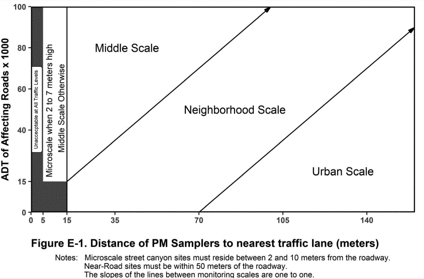
2.5.4 Spacing for Nitrogen Dioxide (NO) Probes
(a) In siting near-road NO 2 monitors as required in section 4.3.2 of appendix D of this part, the monitor probe shall be as near as practicable to the outside nearest edge of the traffic lanes of the target road segment but shall not be located at a distance greater than 50 meters, in the horizontal, from the outside nearest edge of the traffic lanes of the target road segment. Where possible, the near-road NO 2 monitor probe should be within 20 meters of the target road segment.
(b) In siting NO 2 monitors for neighborhood and larger scale monitoring, it is important to minimize near-road influences. Table E–1 of this appendix provides the required minimum separation distances between a roadway and a probe inlet for various ranges of daily roadway traffic. A site with a monitor probe located closer to a roadway than allowed by the Table E–1 requirements should be classified as microscale or middle scale rather than neighborhood or urban scale.
2.6 Probe Material and Pollutant Sampler Residence Time
(a) For the reactive gases (SO 2 , NO 2 , and O 3), approved probe materials must be used for monitors. Studies 25 34 have been conducted to determine the suitability of materials such as polypropylene, polyethylene, polyvinyl chloride, Tygon®, aluminum, brass, stainless steel, copper, borosilicate glass, polyvinylidene fluoride (PVDF), polytetrafluoroethylene (PTFE), perfluoroalkoxy (PFA), and fluorinated ethylene propylene (FEP) for use as intake sampling lines. Of the above materials, only borosilicate glass, PVDF, PTFE, PFA, and FEP have been found to be acceptable for use as intake sampling lines for all the reactive gaseous pollutants. Furthermore, the EPA 25 has specified borosilicate glass, FEP Teflon®, or their equivalents as the only acceptable probe materials for delivering test atmospheres in the determination of reference or equivalent methods. Therefore, borosilicate glass, PVDF, PTFE, PFA, FEP, or their equivalents must be the only material in the sampling train (from probe inlet to the back of the monitor) that can be in contact with the ambient air sample for reactive gas monitors. Nafion TM , which is composed primarily of PTFE, can be considered equivalent to PTFE; it has been shown in tests to exhibit virtually no loss of ozone at 20-second residence times. 35
(b) For volatile organic compound (VOC) monitoring at PAMS, FEP Teflon® is unacceptable as the probe material because of VOC adsorption and desorption reactions on the FEP Teflon®. Borosilicate glass, stainless steel, or their equivalents are the acceptable probe materials for VOC and carbonyl sampling. Care must be taken to ensure that the sample residence time is kept to 20 seconds or less.
(c) No matter how nonreactive the sampling probe material is initially, after a period of use, reactive particulate matter is deposited on the probe walls. Therefore, the time it takes the gas to transfer from the probe inlet to the sampling device is critical. Ozone in the presence of nitrogen oxide (NO) will show significant losses, even in the most inert probe material, when the residence time exceeds 20 seconds. 26 Other studies 27 28 indicate that a 10-second or less residence time is easily achievable. Therefore, sampling probes for all reactive gas monitors for SO 2 , NO 2 , and O 3 must have a sample residence time less than 20 seconds.
2.7 Summary
Table E–3 of this appendix presents a summary of the general requirements for probe siting criteria with respect to distances and heights. Table E–3 requires different elevation distances above the ground for the various pollutants. The discussion in this appendix for each of the pollutants describes reasons for elevating the monitor or probe inlet. The differences in the specified range of heights are based on the vertical concentration gradients. For source oriented and near-road monitors, the gradients in the vertical direction are very large for the microscale, so a small range of heights are used. The upper limit of 15 meters is specified for the consistency between pollutants and to allow the use of a single manifold for monitoring more than one pollutant.
| Pollutant | Scale 9 | Height from ground to probe 8 (meters) | Horizontal or vertical distance from supporting structures 18 to probe inlet (meters) | Distance from drip line of trees to probe 8 (meters) | Distance from roadways to probe 8 (meters) |
|---|---|---|---|---|---|
| N/A—Not applicable. | |||||
| 1 When a probe is located on a rooftop, this separation distance is in reference to walls, parapets, or penthouses located on the roof. | |||||
| 2 Should be greater than 20 meters from the dripline of tree(s) and must be 10 meters from the dripline. | |||||
| 3 Distance from sampler or probe inlet to obstacle, such as a building, must be at least twice the height the obstacle protrudes above the sampler or probe inlet. Sites not meeting this criterion may be classified as microscale or middle scale (see paragraphs 2.3(a) and 2.3(c)). | |||||
| 4 Must have unrestricted airflow in a continuous arc of at least 270 degrees around the probe or sampler; 180 degrees if the probe is on the side of a building or a wall for street canyon monitoring. | |||||
| 5 The probe or sampler should be away from minor sources, such as furnace or incineration flues. The separation distance is dependent on the height of the minor source emission point(s), the type of fuel or waste burned, and the quality of the fuel (sulfur, ash, or lead content). This criterion is designed to avoid undue influences from minor sources. | |||||
| 6 For microscale CO monitoring sites, the probe must be ≥10 meters from a street intersection and preferably at a midblock location. | |||||
| 7 Collocated monitor inlets must be within 4.0 meters of each other and at least 2.0 meters apart for flow rates greater than 200 liters/min or at least 1.0 meter apart for samplers having flow rates less than 200 liters/min to preclude airflow interference, unless a waiver has been granted by the Regional Administrator pursuant to paragraph 3.3.4.2(c) of appendix A of part 58. For PM 2.5 , collocated monitor inlet heights should be within 1.0 meter of each other vertically. | |||||
| 8 All distances listed are expressed as having 2 significant figures. When rounding is performed to assess compliance with these siting requirements, the distance measurements will be rounded such as to retain at least two significant figures. | |||||
| 9 See section 1.2 of appendix D for definitions of monitoring scales. | |||||
| SO 22 3 4 5 | Middle, Neighborhood, Urban, and Regional | 2.0–15 | ≥1.0 | ≥10 | N/A. |
| CO | Micro [downtown or street canyon sites] | 2.5–3.5 | 2.0–10 for downtown areas or street canyon microscale. | ||
| Micro [Near-Road sites] | 2.0–7.0 | ≥1.0 | ≥10 | ≤50 for near-road microscale. | |
| Middle and Neighborhood | 2.0–15 | See Table E–2 of this appendix for middle and neighborhood scales. | |||
| O 3 | Middle, Neighborhood, Urban, and Regional | 2.0–15 | ≥1.0 | ≥10 | See Table E–1. |
| Micro | 2.0–7.0 | ≤50 for near-road micro-scale. | |||
| NO 2 | Middle, Neighborhood, Urban, and Regional | 2.0–15 | ≥1.0 | ≥10 | See Table E–1. |
| PAMS Ozone precursors | Neighborhood and Urban | 2.0–15 | ≥1.0 | ≥10 | See Table E–1. |
| PM, Pb | Micro | 2.0–7.0 | |||
| Middle, Neighborhood, Urban and Regional | 2.0–15 | ≥2.0 (horizontal distance only) | ≥10 | See Figure E–1. | |
3. Open Path Analyzers
3.1 Horizontal and Vertical Placement
(a) For all O 3 and SO 2 monitoring sites and for neighborhood or larger spatial scale NO 2 , and CO sites, at least 80 percent of the monitoring path must be located greater than or equal 2.0 meters and less than or equal to 15 meters above ground level.
(b) Middle scale CO and NO 2 sites must have monitoring paths greater than or equal 2.0 meters and less than or equal to 15 meters above ground level.
(c) Microscale near-road monitoring sites are required to have monitoring paths greater than or equal 2.0 meters and less than or equal to 7.0 meters above ground level.
(d) For microscale carbon monoxide monitors that are being used to measure concentrations near roadways, the monitoring path must be greater than or equal 2.0 meters and less than or equal to 7.0 meters above ground level. If the microscale carbon monoxide monitors measuring concentrations near roadways are in downtown areas or urban street canyons, the monitoring path must be greater than or equal 2.5 meters and less than or equal to 3.5 meters above ground level and at least 90 percent of the monitoring path must be at least 1.0 meter vertically or horizontally away from any supporting structure, walls, parapets, penthouses, etc., and away from dusty or dirty areas. If a significant portion of the monitoring path is located near the side of a building or wall, then it should be located on the windward side of the building relative to the prevailing wind direction during the season of highest concentration potential for the pollutant being measured.
3.2 Spacing From Minor Sources
(a) It is important to understand the monitoring objective for a particular site in order to interpret this requirement. Local minor sources of a primary pollutant, such as SO 2 can cause high concentrations of that particular pollutant at a monitoring site. If the objective for that monitoring site is to investigate these local primary pollutant emissions, then the site will likely be properly located nearby. This type of monitoring site would, in all likelihood, be a microscale type of monitoring site. If a monitoring site is to be used to determine air quality over a much larger area, such as a neighborhood or city, a monitoring agency should avoid placing a monitoring path near local, minor sources, because a plume from a local minor source should not be allowed to inappropriately impact the air quality data collected at a site.
(b) Similarly, local sources of nitric oxide (NO) and ozone-reactive hydrocarbons can have a scavenging effect causing unrepresentatively low concentrations of O 3 in the vicinity of monitoring paths for O 3 . To minimize these potential interferences from nearby minor sources, at least 90 percent of the monitoring path should be at a distance from furnace or incineration flues or other minor sources of SO 2 or NO. The separation distance should take into account the heights of the flues, type of waste or fuel burned, and the sulfur content of the fuel.
3.3 Spacing From Obstructions
(a) Obstacles may scavenge SO 2 , O 3 , or NO 2 , and can act to restrict airflow for any pollutant. To avoid this interference, at least 90 percent of the monitoring path must have unrestricted airflow and should be located at a distance from obstacles. The horizontal distance from the obstacle to the monitoring path must be at least twice the height that the obstacle protrudes above the monitoring path. An obstacle that does not meet the minimum distance requirement is considered an obstruction that restricts airflow to the monitoring path. The EPA does not generally consider objects or obstacles such as flag poles or site towers used for NOy convertors and meteorological sensors, etc. to be deemed obstructions.
(b) A monitoring path located near or along a vertical wall is undesirable because air moving along the wall may be subject to removal mechanisms. At least 90 percent of the monitoring path for open path analyzers must have unrestricted airflow with no obstructions (as defined in paragraph (a) of this section) in a continuous arc of at least 270 degrees. An unobstructed continuous arc of 180 degrees is allowable when the applicable network design criteria specified in appendix D of this part require monitoring in street canyons and the monitoring path is located on the side of a building. This arc must include the predominant wind direction for the season of greatest pollutant concentration potential.
(c) Special consideration must be given to the use of open path analyzers given their inherent potential sensitivity to certain types of interferences and optical obstructions. A monitoring path must be clear of all trees, brush, buildings, plumes, dust, or other optical obstructions, including potential obstructions that may move due to wind, human activity, growth of vegetation, etc. Temporary optical obstructions, such as rain, particles, fog, or snow, should be considered when siting an open path analyzer. Any of these temporary obstructions that are of sufficient density to obscure the light beam will negatively affect the ability of the open path analyzer to continuously measure pollutant concentrations. Transient, but significant obscuration of especially longer measurement paths, could occur as a result of certain meteorological conditions (e.g., heavy fog, rain, snow) and/or aerosol levels that are of a sufficient density to prevent the open path analyzer's light transmission. If certain compensating measures are not otherwise implemented at the onset of monitoring (e.g., shorter path lengths, higher light source intensity), data recovery during periods of greatest primary pollutant potential could be compromised. For instance, if heavy fog or high particulate levels are coincident with periods of projected NAAQS-threatening pollutant potential, the representativeness of the resulting data record in reflecting maximum pollution concentrations may be substantially impaired despite the fact that the site may otherwise exhibit an acceptable, even exceedingly high, overall valid data capture rate.
(d) A sampling station with a monitoring path located closer to an obstacle than required by the criteria in this section should be classified as middle scale or microscale, rather than neighborhood or urban scale, since the measurements from such a station would more closely represent these smaller scales.
(e) For near-road monitoring stations, the monitoring path shall have an unobstructed air flow, where no obstacles exist at or above the height of the monitoring path, between the monitoring path and the outside nearest edge of the traffic lanes of the target road segment.
3.4 Spacing From Trees
(a) Trees can provide surfaces for SO 2 , O 3 , or NO 2 adsorption or reactions. Trees can also act as obstructions in locations where the trees are located between the air pollutant sources or source areas and the monitoring site, and where the trees are of a sufficient height and leaf canopy density to interfere with the normal airflow around the monitoring path. To reduce this possible interference/obstruction, at least 90 percent of the monitoring path should be 20 meters or more from the drip line of trees and must be at least 10 meters from the drip line of trees. If a tree or group of trees could be considered an obstacle, the monitoring path must meet the distance requirements of section 3.3 of this appendix.
(b) The scavenging effect of trees is greater for O 3 than for other criteria pollutants. Monitoring agencies must take steps to consider the impact of trees on ozone monitoring sites and take steps to avoid this problem.
(c) Beginning January 1, 2024, microscale sites of any air pollutant shall have no trees or shrubs located at or above the line-of-sight fetch between the monitoring path and the source under investigation, e.g., a roadway or a stationary source.
3.5 Spacing from Roadways
| Roadway average daily traffic, vehicles per day | Minimum distance 1 3 (meters) | Minimum distance 1 2 3 (meters) |
|---|---|---|
| 1 Distance from the edge of the nearest traffic lane. The distance for intermediate traffic counts should be interpolated from the table values based on the actual traffic count. | ||
| 2 Applicable for ozone open path monitors whose placement was not approved as of December 18, 2006. | ||
| 3 All distances listed are expressed as having 2 significant figures. When rounding is performed to assess compliance with these siting requirements, the distance measurements will be rounded such as to retain at least two significant figures. | ||
| ≤1,000 | 10 | 10 |
| 10,000 | 10 | 20 |
| 15,000 | 20 | 30 |
| 20,000 | 30 | 40 |
| 40,000 | 50 | 60 |
| 70,000 | 100 | 100 |
| ≥110,000 | 250 | 250 |
3.5.1 Spacing for Ozone Monitoring Paths
In siting an O 3 open path analyzer, it is important to minimize destructive interferences form sources of NO, since NO readily reacts with O 3 . Table E–4 of this appendix provides the required minimum separation distances between a roadway and at least 90 percent of a monitoring path for various ranges of daily roadway traffic. A monitoring site with a monitoring path located closer to a roadway than allowed by the Table E–4 requirements should be classified as microscale or middle scale, rather than neighborhood or urban scale, since the measurements from such a site would more closely represent these smaller scales. The monitoring path(s) must not cross over a roadway with an average daily traffic count of 10,000 vehicles per day or more. For locations where a monitoring path crosses a roadway with fewer than 10,000 vehicles per day, monitoring agencies must consider the entire segment of the monitoring path in the area of potential atmospheric interference from automobile emissions. Therefore, this calculation must include the length of the monitoring path over the roadway plus any segments of the monitoring path that lie in the area between the roadway and minimum separation distance, as determined from Table E–4 of this appendix. The sum of these distances must not be greater than 10 percent of the total monitoring path length.
3.5.2 Spacing for Carbon Monoxide Monitoring Paths
(a) Near-road microscale CO monitoring sites, including those located in downtown areas, urban street canyons, and other near-road locations such as those adjacent to highly trafficked roads, are intended to provide a measurement of the influence of the immediate source on the pollution exposure on the adjacent area.
(b) Microscale CO monitoring paths in downtown areas or urban street canyon locations shall be located a minimum distance of 2.0 meters and a maximum distance of 10 meters from the edge of the nearest traffic lane.
(c) Microscale CO monitoring paths in downtown areas or urban street canyon locations shall be located at least 10 meters from an intersection, preferably at a midblock location. Midblock locations are preferable to intersection locations because intersections represent a much smaller portion of downtown space than do the streets between them. Pedestrian exposure is probably also greater in street canyon/corridors than at intersections.
(d) Neighborhood scale CO monitoring paths in downtown areas or urban street canyon locations shall be located according to the requirements in Table E–5 of this appendix.
| Roadway average daily traffic, vehicles per day | Minimum distance 1 2 (meters) |
|---|---|
| 1 Distance from the edge of the nearest traffic lane. The distance for intermediate traffic counts should be interpolated from the table values based on the actual traffic count. | |
| 2 All distances listed are expressed as having 2 significant figures. When rounding is performed to assess compliance with these siting requirements, the distance measurements will be rounded such as to retain at least two significant figures. | |
| ≤10,000 | 10 |
| 15,000 | 25 |
| 20,000 | 45 |
| 30,000 | 80 |
| 40,000 | 115 |
| 50,000 | 135 |
| ≥60,000 | 150 |
3.5.3 Spacing for Nitrogen Dioxide (NO 2) Monitoring Paths
(a) In siting near-road NO 2 monitors as required in section 4.3.2 of appendix D of this part, the monitoring path shall be as near as practicable to the outside nearest edge of the traffic lanes of the target road segment but shall not be located at a distance greater than 50 meters, in the horizontal, from the outside nearest edge of the traffic lanes of the target road segment.
(b) In siting NO 2 open path monitors for neighborhood and larger scale monitoring, it is important to minimize near-road influences. Table E–5 of this appendix provides the required minimum separation distances between a roadway and at least 90 percent of a monitoring path for various ranges of daily roadway traffic. A site with a monitoring path located closer to a roadway than allowed by the Table E–4 requirements should be classified as microscale or middle scale rather than neighborhood or urban scale. The monitoring path(s) must not cross over a roadway with an average daily traffic count of 10,000 vehicles per day or more. For locations where a monitoring path crosses a roadway with fewer than 10,000 vehicles per day, monitoring agencies must consider the entire segment of the monitoring path in the area of potential atmospheric interference form automobile emissions. Therefore, this calculation must include the length of the monitoring path over the roadway plus any segments of the monitoring path that lie in the area between the roadway and minimum separation distance, as determined from Table E–5 of this appendix. The sum of these distances must not be greater than 10 percent of the total monitoring path length.
3.6 Cumulative Interferences on a Monitoring Path
The cumulative length or portion of a monitoring path that is affected by minor sources, trees, or roadways must not exceed 10 percent of the total monitoring path length.
3.7 Maximum Monitoring Path Length
The monitoring path length must not exceed 1.0 kilometer for open path analyzers in neighborhood, urban, or regional scale. For middle scale monitoring sites, the monitoring path length must not exceed 300 meters. In areas subject to frequent periods of dust, fog, rain, or snow, consideration should be given to a shortened monitoring path length to minimize loss of monitoring data due to these temporary optical obstructions. For certain ambient air monitoring scenarios using open path analyzers, shorter path lengths may be needed in order to ensure that the monitoring site meets the objectives and spatial scales defined in appendix D to this part. The Regional Administrator may require shorter path lengths, as needed on an individual basis, to ensure that the SLAMS sites meet the appendix D requirements. Likewise, the Administrator may specify the maximum path length used at NCore monitoring sites.
3.8 Summary
Table E–6 of this appendix presents a summary of the general requirements for monitoring path siting criteria with respect to distances and heights. Table E–6 requires different elevation distances above the ground for the various pollutants. The discussion in this appendix for each of the pollutants describes reasons for elevating the monitoring path. The differences in the specified range of heights are based on the vertical concentration gradients. For source oriented and near-road monitors, the gradients in the vertical direction are very large for the microscale, so a small range of heights are used. The upper limit of 15 meters is specified for the consistency between pollutants and to allow the use of a monitoring path for monitoring more than one pollutant.
| Pollutant | Maximum monitoring path length | Height from ground to 80% of monitoring path (meters) | Horizontal or vertical distance from supporting structures to 90% of monitoring path (meters) | Distance from trees to 90% of monitoring path (meters) | Distance from roadways to monitoring path (meters) |
|---|---|---|---|---|---|
| N/A—Not applicable. | |||||
| 1 Monitoring path for open path analyzers is applicable only to middle or neighborhood scale CO monitoring, middle, neighborhood, urban, and regional scale NO 2 monitoring, and all applicable scales for monitoring SO 2 , O 3 , and O 3 precursors. | |||||
| 2 When the monitoring path is located on a rooftop, this separation distance is in reference to walls, parapets, or penthouses located on roof. | |||||
| 3 At least 90 percent of the monitoring path should be greater than 20 meters from the dripline of tree(s) and must be 10-meters from the dripline. | |||||
| 4 Distance from 90 percent of monitoring path to obstacle, such as a building, must be at least twice the height the obstacle protrudes above the monitoring path. Sites not meeting this criterion may be classified as microscale or middle scale (see text). | |||||
| 5 Must have unrestricted airflow 270 degrees around at least 90 percent of the monitoring path; 180 degrees if the monitoring path is adjacent to the side of a building or a wall for street canyon monitoring. | |||||
| 6 The monitoring path should be away from minor sources, such as furnace or incineration flues. The separation distance is dependent on the height of the minor source's emission point (such as a flue), the type of fuel or waste burned, and the quality of the fuel (sulfur, ash, or lead content). This criterion is designed to avoid undue influences from minor sources. | |||||
| 7 For microscale CO monitoring sites, the monitoring path must be ≥10. meters from a street intersection and preferably at a midblock location. | |||||
| 8 All distances listed are expressed as having 2 significant figures. When rounding is performed to assess compliance with these siting requirements, the distance measurements will be rounded such as to retain at least two significant figures. | |||||
| 9 See section 1.2 of appendix D for definitions of monitoring scales. | |||||
| 10 See section 3.7 of this appendix. | |||||
| SO 2 3456 | <= 300 m for Middle <= 1.0 km for Neighborhood, Urban, and Regional | 2.0–15 | ≥1.0 | ≥10 | N/A. |
| CO457 | <= 300 m for Micro [downtown or street canyon sites] | 2.5–3.5 | ≥1.0 | ≥10 | 2.0–10 for downtown areas or street canyon microscale. |
| <= 300 m for Micro [Near-Road sites] | 2.0–7.0 | ≤50 for near-road microscale. | |||
| <= 300 m for Middle | 2.0–15 | See Table E–5 of this appendix for middle and neighborhood scales. | |||
| <= 1.0 km for Neighborhood | |||||
| O 3345 | <= 300 m for Middle | ||||
| <= 1.0 km for Neighborhood, Urban, and Regional | 2.0–15 | ≥1.0 | ≥10 | See Table E–4. | |
| NO 2345 | Between 50 m–300 m for Micro (Near-Road) | 2.0–7.0 | ≤50 for near-road micro-scale. | ||
| <= 300 m for Middle | ≥1.0 | ≥10 | |||
| <= 1.0 km for Neighborhood, Urban, and Regional | 2.0–15 | See Table E–4. | |||
| PAMS Ozone precursors 345 | <= 1.0 km for Neighborhood and Urban | 2.0–15 | ≥1.0 | ≥10 | See Table E–4. |
4. Waiver Provisions
Most sampling probes or monitors can be located so that they meet the requirements of this appendix. New sites, with rare exceptions, can be located within the limits of this appendix. However, some existing sites may not meet these requirements and may still produce useful data for some purposes. The EPA will consider a written request from the State, or where applicable local, agency to waive one or more siting criteria for some monitoring sites providing that the State or their designee can adequately demonstrate the need (purpose) for monitoring or establishing a monitoring site at that location.
4.1 For a proposed new site, a waiver may be granted only if both the following criteria are met:
4.1.1 The proposed new site can be demonstrated to be as representative of the monitoring area as it would be if the siting criteria were being met.
4.1.2 The monitor or probe cannot reasonably be located so as to meet the siting criteria because of physical constraints (e.g., inability to locate the required type of site the necessary distance from roadways or obstructions).
4.2 For an existing site, a waiver may be granted if either the criterion in section 4.1.1 or the criterion in 4.1.2 of this appendix is met.
4.3 Cost benefits, historical trends, and other factors may be used to add support to the criteria in sections 4.1.1 and 4.1.2 of this appendix; however, by themselves, they will not be acceptable reasons for the EPA to grant a waiver. Written requests for waivers must be submitted to the Regional Administrator. Granted waivers must be renewed minimally every 5 years and ideally as part of the network assessment as defined in §58.10(d). The approval date of the waiver must be documented in the annual monitoring network plan to support the requirements of §58.10(a)(1) and 58.10(b)(10).
5. References
1. Bryan, R.J., R.J. Gordon, and H. Menck. Comparison of High Volume Air Filter Samples at Varying Distances from Los Angeles Freeway. University of Southern California, School of Medicine, Los Angeles, CA. (Presented at 66th Annual Meeting of Air Pollution Control Association. Chicago, IL. June 24–28, 1973. APCA 73–158.)
2. Teer, E.H. Atmospheric Lead Concentration Above an Urban Street. Master of Science Thesis, Washington University, St. Louis, MO. January 1971.
3. Bradway, R.M., F.A. Record, and W.E. Belanger. Monitoring and Modeling of Resuspended Roadway Dust Near Urban Arterials. GCA Technology Division, Bedford, MA. (Presented at 1978 Annual Meeting of Transportation Research Board, Washington, DC. January 1978.)
4. Pace, T.G., W.P. Freas, and E.M. Afify. Quantification of Relationship Between Monitor Height and Measured Particulate Levels in Seven U.S. Urban Areas. U.S. Environmental Protection Agency, Research Triangle Park, NC. (Presented at 70th Annual Meeting of Air Pollution Control Association, Toronto, Canada. June 20–24, 1977. APCA 77–13.4.)
5. Harrison, P.R. Considerations for Siting Air Quality Monitors in Urban Areas. City of Chicago, Department of Environmental Control, Chicago, IL. (Presented at 66th Annual Meeting of Air Pollution Control Association, Chicago, IL. June 24–28, 1973. APCA 73–161.)
6. Study of Suspended Particulate Measurements at Varying Heights Above Ground. Texas State Department of Health, Air Control Section, Austin, TX. 1970. p.7.
7. Rodes, C.E. and G.F. Evans. Summary of LACS Integrated Pollutant Data. In: Los Angeles Catalyst Study Symposium. U.S. Environmental Protection Agency, Research Triangle Park, NC. EPA Publication No. EPA–600/4–77–034. June 1977.
8. Lynn, D.A. et al. National Assessment of the Urban Particulate Problem: Volume 1, National Assessment. GCA Technology Division, Bedford, MA. U.S. Environmental Protection Agency, Research Triangle Park, NC. EPA Publication No. EPA–450/3–75–024. June 1976.
9. Pace, T.G. Impact of Vehicle-Related Particulates on TSP Concentrations and Rationale for Siting Hi-Vols in the Vicinity of Roadways. OAQPS, U.S. Environmental Protection Agency, Research Triangle Park, NC. April 1978.
10. Ludwig, F.L., J.H. Kealoha, and E. Shelar. Selecting Sites for Monitoring Total Suspended Particulates. Stanford Research Institute, Menlo Park, CA. Prepared for U.S. Environmental Protection Agency, Research Triangle Park, NC. EPA Publication No. EPA–450/3–77–018. June 1977, revised December 1977.
11. Ball, R.J. and G.E. Anderson. Optimum Site Exposure Criteria for SO 2 Monitoring. The Center for the Environment and Man, Inc., Hartford, CT. Prepared for U.S. Environmental Protection Agency, Research Triangle Park, NC. EPA Publication No. EPA–450/3–77–013. April 1977.
12. Ludwig, F.L. and J.H.S. Kealoha. Selecting Sites for Carbon Monoxide Monitoring. Stanford Research Institute, Menlo Park, CA. Prepared for U.S. Environmental Protection Agency, Research Triangle Park, NC. EPA Publication No. EPA–450/3–75–077. September 1975.
13. Ludwig, F.L. and E. Shelar. Site Selection for the Monitoring of Photochemical Air Pollutants. Stanford Research Institute, Menlo Park, CA. Prepared for U.S. Environmental Protection Agency, Research Triangle Park, NC. EPA Publication No. EPA–450/3–78–013. April 1978.
14. Lead Analysis for Kansas City and Cincinnati, PEDCo Environmental, Inc., Cincinnati, OH. Prepared for U.S. Environmental Protection Agency, Research Triangle Park, NC. EPA Contract No. 66–02–2515, June 1977.
15. Barltrap, D. and C.D. Strelow. Westway Nursery Testing Project. Report to the Greater London Council. August 1976.
16. Daines, R. H., H. Moto, and D. M. Chilko. Atmospheric Lead: Its Relationship to Traffic Volume and Proximity to Highways. Environ. Sci. and Technol., 4:318, 1970.
17. Johnson, D. E., et al. Epidemiologic Study of the Effects of Automobile Traffic on Blood Lead Levels, Southwest Research Institute, Houston, TX. Prepared for U.S. Environmental Protection Agency, Research Triangle Park, NC. EPA–600/1–78–055, August 1978.
18. Air Quality Criteria for Lead. Office of Research and Development, U.S. Environmental Protection Agency, Washington, DC EPA–600/8–83–028 aF–dF, 1986, and supplements EPA–600/8–89/049F, August 1990. (NTIS document numbers PB87–142378 and PB91–138420.)
19. Lyman, D. R. The Atmospheric Diffusion of Carbon Monoxide and Lead from an Expressway, Ph.D. Dissertation, University of Cincinnati, Cincinnati, OH. 1972.
20. Wechter, S.G. Preparation of Stable Pollutant Gas Standards Using Treated Aluminum Cylinders. ASTM STP. 598:40–54, 1976.
21. Wohlers, H.C., H. Newstein and D. Daunis. Carbon Monoxide and Sulfur Dioxide Adsorption On and Description From Glass, Plastic and Metal Tubings. J. Air Poll. Con. Assoc. 17:753, 1976.
22. Elfers, L.A. Field Operating Guide for Automated Air Monitoring Equipment. U.S. NTIS. p. 202, 249, 1971.
23. Hughes, E.E. Development of Standard Reference Material for Air Quality Measurement. ISA Transactions, 14:281–291, 1975.
24. Altshuller, A.D. and A.G. Wartburg. The Interaction of Ozone with Plastic and Metallic Materials in a Dynamic Flow System. Intern. Jour. Air and Water Poll., 4:70–78, 1961.
25. Code of Federal Regulations. 40 CFR 53.22, July 1976.
26. Butcher, S.S. and R.E. Ruff. Effect of Inlet Residence Time on Analysis of Atmospheric Nitrogen Oxides and Ozone, Anal. Chem., 43:1890, 1971.
27. Slowik, A.A. and E.B. Sansone. Diffusion Losses of Sulfur Dioxide in Sampling Manifolds. J. Air. Poll. Con. Assoc., 24:245, 1974.
28. Yamada, V.M. and R.J. Charlson. Proper Sizing of the Sampling Inlet Line for a Continuous Air Monitoring Station. Environ. Sci. and Technol., 3:483, 1969.
29. Koch, R.C. and H.E. Rector. Optimum Network Design and Site Exposure Criteria for Particulate Matter, GEOMET Technologies, Inc., Rockville, MD. Prepared for U.S. Environmental Protection Agency, Research Triangle Park, NC. EPA Contract No. 68–02–3584. EPA 450/4–87–009. May 1987.
30. Burton, R.M. and J.C. Suggs. Philadelphia Roadway Study. Environmental Monitoring Systems Laboratory, U.S. Environmental Protection Agency, Research Triangle Park, N.C. EPA–600/4–84–070 September 1984.
31. Technical Assistance Document for Sampling and Analysis of Ozone Precursors. Atmospheric Research and Exposure Assessment Laboratory, U.S. Environmental Protection Agency, Research Triangle Park, NC 27711. EPA 600/8–91–215. October 1991.
32. Quality Assurance Handbook for Air Pollution Measurement Systems: Volume IV. Meteorological Measurements. Atmospheric Research and Exposure Assessment Laboratory, U.S. Environmental Protection Agency, Research Triangle Park, NC 27711. EPA 600/4–90–0003. August 1989.
33. On-Site Meteorological Program Guidance for Regulatory Modeling Applications. Office of Air Quality Planning and Standards, U.S. Environmental Protection Agency, Research Triangle Park, NC 27711. EPA 450/4–87–013. June 1987F.
34. Johnson, C., A. Whitehill, R. Long, and R. Vanderpool. Investigation of Gaseous Criteria Pollutant Transport Efficiency as a Function of Tubing Material. U.S. Environmental Protection Agency, Research Triangle Park, NC 27711. EPA/600/R–22/212. August 2022.
35. Hannah Halliday, Cortina Johnson, Tad Kleindienst, Russell Long, Robert Vanderpool, and Andrew Whitehill. Recommendations for Nationwide Approval of Nafion TM Dryers Upstream of UV-Absorption Ozone Analyzers. U.S. Environmental Protection Agency, Research Triangle Park, NC 27711. EPA/600/R–20/390. November 2020.
Appendix G to Part 58—Uniform Air Quality Index (AQI) and Daily Reporting
1. General Information
2. Reporting Requirements
3. Data Handling
1. General Information
1.1 AQI Overview. The AQI is a tool that simplifies reporting air quality to the public in a nationally uniform and easy to understand manner. The AQI converts concentrations of pollutants, for which the EPA has established a national ambient air quality standard (NAAQS), into a uniform scale from 0–500. These pollutants are ozone (O 3), particulate matter (PM 2.5 , PM 10), carbon monoxide (CO), sulfur dioxide (SO 2), and nitrogen dioxide (NO 2). The scale of the index is divided into general categories that are associated with health messages.
2. Reporting Requirements
2.1 Applicability. The AQI must be reported daily for a metropolitan statistical area (MSA) with a population over 350,000. When it is useful and possible, it is recommended, but not required for an area to report a sub-daily AQI as well.
2.2 Contents of AQI Report.
2.2.1 Content of AQI Report Requirements. An AQI report must contain the following:
a. The reporting area(s) (the MSA or subdivision of the MSA).
b. The reporting period (the day for which the AQI is reported).
c. The main pollutant (the pollutant with the highest index value).
d. The AQI (the highest index value).
e. The category descriptor and index value associated with the AQI and, if choosing to report in a color format, the associated color. Use only the following descriptors and colors for the six AQI categories:
| For this AQI | Use this descriptor | And this color 1 |
|---|---|---|
| 1 Specific color definitions can be found in the most recent reporting guidance (Technical Assistance Document for the Reporting of Daily Air Quality), which can be found at https://www.airnow.gov/publications/air-quality-index/technical-assistance-document-for-reporting-the-daily-aqi/. | ||
| 0 to 50 | “Good” | Green. |
| 51 to 100 | “Moderate” | Yellow. |
| 101 to 150 | “Unhealthy for Sensitive Groups” | Orange. |
| 151 to 200 | “Unhealthy” | Red. |
| 201 to 300 | “Very Unhealthy” | Purple. |
| 301 and above | “Hazardous” | Maroon 1 . |
f. The pollutant specific sensitive groups for any reported index value greater than 100. The sensitive groups for each pollutant are identified as part of the periodic review of the air quality criteria and the NAAQS. For convenience, the EPA lists the relevant groups for each pollutant in the most recent reporting guidance (Technical Assistance Document for the Reporting of Daily Air Quality), which can be found at https://www.airnow.gov/publications/air-quality-index/technical-assistance-document-for-reporting-the-daily-aqi/.
2.2.2 Contents of AQI Report When Applicable. When appropriate, the AQI report may also contain the following, but such information is not required:
a. Appropriate health and cautionary statements.
b. The name and index value for other pollutants, particularly those with an index value greater than 100.
c. The index values for sub-areas of your MSA.
d. Causes for unusually high AQI values.
e. Pollutant concentrations.
f. Generally, the AQI report applies to an area's MSA only. However, if a significant air quality problem exists (AQI greater than 100) in areas significantly impacted by the MSA but not in it (for example, O 3 concentrations are often highest downwind and outside an urban area), the report should identify these areas and report the AQI for these areas as well.
2.3. Communication, Timing, and Frequency of AQI Report. The daily AQI must be reported 7 days per week and made available via website or other means of public access. The daily AQI report represents the air quality for the previous day. Exceptions to this requirement are in section 2.4 of this appendix.
a. Reporting the AQI sub-daily is recommended, but not required, to provide more timely air quality information to the public for making health-protective decisions.
b. Submitting hourly data in real-time to the EPA's AirNow (or future analogous) system is recommended, but not required, and assists the EPA in providing timely air quality information to the public for making health-protective decisions.
c. Submitting hourly data for appropriate monitors (referenced in section 3.2 of this appendix) satisfies the daily AQI reporting requirement because the AirNow system makes daily and sub-daily AQI reports widely available through its website and other communication tools.
d. Forecasting the daily AQI provides timely air quality information to the public and is recommended but not required. Sub-daily forecasts are also recommended, especially when air quality is expected to vary substantially throughout the day, like during wildfires. Long-term (multi-day) forecasts can also be made available when useful.
2.4. Exceptions to Reporting Requirements.
a. If the index value for a particular pollutant remains below 50 for a season or year, then it may be excluded from the calculation of the AQI in section 3 of this appendix.
b. If all index values remain below 50 for a year, then the AQI may be reported at the discretion of the reporting agency. In subsequent years, if pollutant levels rise to where the AQI would be above 50, then the AQI must be reported as required in section 2 of this appendix.
c. As previously mentioned in section 2.3 of this appendix, submitting hourly data in real-time from appropriate monitors (referenced in section 3.2 of this appendix) to the EPA's AirNow (or future analogous) system satisfies the daily AQI reporting requirement.
3. Data Handling.
3.1 Relationship of AQI and pollutant concentrations. For each pollutant, the AQI transforms ambient concentrations to a scale from 0 to 500. As appropriate, the AQI is associated with the NAAQS for each pollutant. In most cases, the index value of 100 is associated with the numerical level of the short-term standard (i.e., averaging time of 24-hours or less) for each pollutant. The index value of 50 is associated with the numerical level of the annual standard for a pollutant, if there is one, at one-half the level of the short-term standard for the pollutant or at the level at which it is appropriate to begin to provide guidance on cautionary language. Higher categories of the index are based on the potential for increasingly serious health effects to occur following exposure and increasing proportions of the population that are likely to be affected. The reported AQI corresponds to the pollutant with the highest calculated AQI. For the purposes of reporting the AQI, the sub-indexes for PM 10 and PM 2.5 are to be considered separately. The pollutant responsible for the highest index value (the reported AQI) is called the “main” pollutant for that day.
3.2 Monitors Used for AQI Reporting. Concentration data from State/Local Air Monitoring Station (SLAMS) or parts of the SLAMS required by 40 CFR 58.10 must be used for each pollutant except PM. For PM, calculate and report the AQI on days for which air quality data has been measured (e.g., from continuous PM 2.5 monitors required in appendix D to this part). PM measurements may be used from monitors that are not reference or equivalent methods (for example, continuous PM 10 or PM 2.5 monitors). Detailed guidance for relating non-approved measurements to approved methods by statistical linear regression is referenced here:
Reference for relating non-approved PM measurements to approved methods (Eberly, S., T. Fitz-Simons, T. Hanley, L. Weinstock., T. Tamanini, G. Denniston, B. Lambeth, E. Michel, S. Bortnick. Data Quality Objectives (DQOs) For Relating Federal Reference Method (FRM) and Continuous PM 2.5 Measurements to Report an Air Quality Index (AQI). U.S. Environmental Protection Agency, Research Triangle Park, NC. EPA–454/B–02–002, November 2002).
3.3 AQI Forecast. The AQI can be forecasted at least 24-hours in advance using the most accurate and reasonable procedures considering meteorology, topography, availability of data, and forecasting expertise. The guidance document, “Guidelines for Developing an Air Quality (Ozone and PM 2.5) Forecasting Program,” can be found at https://www.airnow.gov/publications/weathercasters/guidelines-developing-air-quality-forecasting-program/.
3.4 Calculation and Equations.
a. The AQI is the highest value calculated for each pollutant as follows:
i. Identify the highest concentration among all of the monitors within each reporting area and truncate as follows:
(A) Ozone—truncate to 3 decimal places
PM 2.5 —truncate to 1 decimal place
PM 10 —truncate to integer
CO—truncate to 1 decimal place
SO 2 —truncate to integer
NO 2 —truncate to integer
(B) [Reserved]
ii. Using table 2 to this appendix, find the two breakpoints that contain the concentration.
iii. Using equation 1 to this appendix, calculate the index.
iv. Round the index to the nearest integer.
| These breakpoints | Equal these AQI's | |||||||
|---|---|---|---|---|---|---|---|---|
| O 3 (ppm) 8-hour | O 3 (ppm) 1-hour 1 | PM 2.5 (µg/m 3) 24-hour | PM 10 (µg/m 3) 24-hour | CO (ppm) 8-hour | SO 2 (ppb) 1-hour | NO 2 (ppb) 1-hour | AQI | Category |
| 1 Areas are generally required to report the AQI based on 8-hour ozone values. However, there are a small number of areas where an AQI based on 1-hour ozone values would be more precautionary. In these cases, in addition to calculating the 8-hour ozone index value, the 1-hour ozone index value may be calculated, and the maximum of the two values reported. | ||||||||
| 2 8-hour O 3 concentrations do not define higher AQI values (>301). AQI values > 301 are calculated with 1-hour O 3 concentrations. | ||||||||
| 3 1-hr SO 2 concentrations do not define higher AQI values (≥200). AQI values of 200 or greater are calculated with 24-hour SO 2 concentration. | ||||||||
| 4 AQI values between breakpoints are calculated using equation 1 to this appendix. For AQI values in the hazardous category, AQI values greater than 500 should be calculated using equation 1 and the concentration specified for the AQI value of 500. The AQI value of 500 are as follows: O 3 1-hour—0.604 ppm; PM 2.5 24-hour—325.4 µg/m 3 ; PM 10 24-hour—604 µg/m 3 ; CO ppm—50.4 ppm; SO 2 1-hour—1004 ppb; and NO 2 1-hour—2049 ppb. | ||||||||
| 0.000–0.054 | 0.0–9.0 | 0–54 | 0.0–4.4 | 0–35 | 0–53 | 0–50 | Good. | |
| 0.055–0.070 | 9.1–35.4 | 55–154 | 4.5–9.4 | 36–75 | 54–100 | 51–100 | Moderate. | |
| 0.071–0.085 | 0.125–0.164 | 35.5–55.4 | 155–254 | 9.5–12.4 | 76–185 | 101–360 | 101–150 | Unhealthy for Sensitive Groups. |
| 0.086–0.105 | 0.165–0.204 | 55.5–125.4 | 255–354 | 12.5–15.4 | 3 186–304 | 361–649 | 151–200 | Unhealthy. |
| 0.106–0.200 | 0.205–0.404 | 125.5—225.4 | 355–424 | 15.5–30.4 | 3 305–604 | 650–1249 | 201–300 | Very Unhealthy. |
| 0.201−(2) | 0.405+ | 225.5+ | 425+ | 30.5+ | 3 605+ | 1250+ | 301+ | 4 Hazardous. |
b. If the concentration is equal to a breakpoint, then the index is equal to the corresponding index value in table 2 to this appendix. However, equation 1 to this appendix can still be used. The results will be equal. If the concentration is between two breakpoints, then calculate the index of that pollutant with equation 1. It should also be noted that in some areas, the AQI based on 1-hour O 3 will be more precautionary than using 8-hour values (see footnote 1 to table 2). In these cases, the 1-hour values as well as 8-hour values may be used to calculate index values and then use the maximum index value as the AQI for O 3.
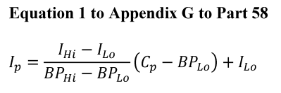
Where:
I p = the index value for pollutant p .
C p = the truncated concentration of pollutant p .
BP Hi = the breakpoint that is greater than or equal to C p .
BP Lo = the breakpoint that is less than or equal to C p .
I Hi = the AQI value corresponding to BP Hi .
I lo = the AQI value corresponding to BP Lo .
c. If the concentration is larger than the highest breakpoint in table 2 to this appendix then the last two breakpoints in table 2 may be used when equation 1 to this appendix is applied.
Example:
d. Using table 2 and equation 1 to this appendix, calculate the index value for each of the pollutants measured and select the one that produces the highest index value for the AQI. For example, if a PM 10 value of 210 µg/m 3 is observed, a 1-hour O 3 value of 0.156 ppm, and an 8-hour O 3 value of 0.130 ppm, then do this:
i. Find the breakpoints for PM 10 at 210 µg/m 3 as 155 µg/m 3 and 254 µg/m 3 , corresponding to index values 101 and 150;
ii. Find the breakpoints for 1-hour O 3 at 0.156 ppm as 0.125 ppm and 0.164 ppm, corresponding to index values 101 and 150;
iii. Find the breakpoints for 8-hour O 3 at 0.130 ppm as 0.116 ppm and 0.374 ppm, corresponding to index values 201 and 300;
iv. Apply equation 21 to this appendix for 210 µg/m 3 , PM 10 :
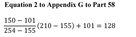
v. Apply equation 3 to this appendix for 0.156 ppm, 1-hour O 3 :
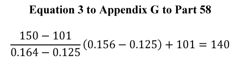
vi. Apply equation 4 to this appendix for 0.130 ppm, 8-hour O 3 :
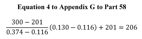
vii. Find the maximum, 206. This is the AQI. A minimal AQI report could read: “Today, the AQI for my city is 206, which is Very Unhealthy, due to ozone.” It would then reference the associated sensitive groups.


Based on the Environmental Protection Agency's (EPA's) reconsideration of the air quality criteria and the national ambient air quality standards (NAAQS) for particulate matter (PM), the EPA is revising the primary annual PM 2.5 standard by lowering the level from 12.0 µg/m 3 to 9.0 µg/m 3 . The Agency is retaining the current primary 24-hour PM 2.5 standard and the primary 24-hour PM 10 standard. The Agency also is not changing the secondary 24-hour PM 2.5 standard, secondary annual PM 2.5 standard, and secondary 24-hour PM 10 standard at this time. The EPA is also finalizing revisions to other key aspects related to the PM NAAQS, including revisions to the Air Quality Index (AQI) and monitoring requirements for the PM NAAQS.
DATES: This final rule is effective May 6, 2024, published in the Federal Register March 6, 2024, page 16202.
View final rule.
| §50.20 National primary ambient air quality standards for PM2.5. | ||
| Entire section | Added | View text |
| Appendix K to Part 50 - Interpretation of the National Ambient Air Quality Standards for Particulate Matter | ||
| Section 1.0 paragraph (b) | Revised | View text |
| Section 2.3 paragraph (d) | Added | View text |
| Section 3.0 paragraphs (a) and (b) | Added | View text |
| Appendix L to Part 50 - Reference Method for the Determination of Fine Particulate Matter as PM2.5 in the Atmosphere | ||
| Section 7.3.4 | Revised | View text |
| Section 7.3.4.5 | Added | View text |
| Appendix N to Part 50 - Interpretation of the National Ambient Air Quality Standards for PM2.5 | ||
| Section 1.0 paragraph (a) | Revised | View text |
| Section 3.0 paragraph (d)(3) | Added | View text |
| Section 4.1 paragraph (a) | Revised | View text |
| Section 4.2 paragraph (a) | Revised | View text |
| §53.4 Applications for reference or equivalent method determinations. | ||
| (a), (d) | Revised | View text |
| (b)(7) | Added | View text |
| §53.8 Designation of reference and equivalent methods. | ||
| (a) | Revised | View text |
| §53.14 Modification of a reference or equivalent method. | ||
| (c)(4)-(6) | Revised | View text |
| Table A–1 to Subpart A of Part 53—Summary of Applicable Requirements for Reference and Equivalent Methods for Air Monitoring of Criteria Pollutants | ||
| Entire table | Revised | View text |
| Table B-1 to Subpart B of Part 53- Performance Limit Specifications for Automated Methods | ||
| Footnote 4 | Revised | View text |
| Table B-3 to Subpart B of Part 53 - Interferent Test Concentration,1 Parts per Million | ||
| Entire table | Revised | View text |
| Appendix A to Subpart B of Part 53 - Optional Forms for Reporting Test Results | ||
| Figures B-3 and B-5 | Revised | View text |
| §53.35 Test procedure for Class II and Class III methods for PM2.5 and PM10−2.5. | ||
| (b)(1)(ii)(D) | Revised | View text |
| Table C-4 to Subpart C of Part 53—Test Specifications for PM10, PM2.5, and PM10–2.5 Candidate Equivalent Methods | ||
| Entire table | Revised | View text |
| §53.43 Test procedures. | ||
| Formulas in (a)(2)(xvi) and (c)(2)(iv) | Revised | View text |
| §53.51 Demonstration of compliance with design specifications and manufacturing and test requirements. | ||
| (d)(2) | Revised | View text |
| §53.61 Test conditions. | ||
| (g) | Revised | View text |
| §58.1 Definitions. | ||
| Definition for ”Approved regional method (ARM)” | Removed | View text |
| Definition for ”Traceable” | Removed | View text |
| §58.10 Annual monitoring network plan and periodic network assessment. | ||
| (a)(1), (b)(10), (b)(13), (d) | Revised | View text |
| (b)(14) | Added | View text |
| §58.11 Network technical requirements. | ||
| (a)(2), (e) | Revised | View text |
| §58.12 Operating schedules. | ||
| (d)(1) | Revised | View text |
| §58.15 Annual air monitoring data certification. | ||
| Entire section | Revised | View text |
| §58.20 Special purpose monitors (SPM). | ||
| (b)-(e) | Revised | View text |
| Appendix A to Part 58 - Quality Assurance Requirements for Monitors used in Evaluations of National Ambient Air Quality Standards | ||
| Entire appendix | Revised | View text |
| Appendix B to Part 58 - Quality Assurance Requirements for Prevention of Significant Deterioration (PSD) Air Monitoring | ||
| Entire appendix | View text | |
| Appendix C to Part 58—Ambient Air Quality Monitoring Methodology | ||
| Section 2 | Revised | View text |
| Appendix D to Part 58—Network Design Criteria for Ambient Air Quality Monitoring | ||
| Sections 1, 1.1(b), introductory text before table in 4.7.1(a), 4.7.1(b)(3), 4.7.2 | Revised | View text |
| Appendix E to Part 58—Probe and Monitoring Path Siting Criteria for Ambient Air Quality Monitoring | ||
| Entire appendix | Revised | View text |
| Appendix G to Part 58—Uniform Air Quality Index (AQI) and Daily Reporting | ||
| Entire appendix | Revised | View text |
New Text
Appendix K to Part 50 - Interpretation of the National Ambient Air Quality Standards for Particulate Matter
* * * *
(b) The terms used in this appendix are defined as follows:
Average refers to the arithmetic mean of the estimated number of exceedances per year, as per section 3.1 of this appendix.
Collocated monitors refer to two or more air measurement instruments for the same parameter (e.g., PM 10 mass) operated at the same site location, and whose placement is consistent with part 53 of this chapter. For purposes of considering a combined site record in this appendix, when two or more monitors are operated at the same site, one monitor is designated as the “primary” monitor with any additional monitors designated as “collocated.” It is implicit in these appendix procedures that the primary monitor and collocated monitor(s) are all reference or equivalent methods; however, it is not a requirement that the primary and collocated monitors utilize the same specific sampling and analysis method.
Combined site data record is the data set used for performing computations in this appendix and represents data for the primary monitors augmented with data from collocated monitors according to the procedure specified in section 3.0(a) of this appendix.
Daily value for PM10 refers to the 24-hour average concentration of PM 10 calculated or measured from midnight to midnight (local time).
Exceedance means a daily value that is above the level of the 24-hour standard after rounding to the nearest 10 µg/m 3i.e., values ending in 5 or greater are to be rounded up).
Expected annual value is the number approached when the annual values from an increasing number of years are averaged, in the absence of long-term trends in emissions or meteorological conditions.
Primary monitors are suitable monitors designated by a State or local agency in their annual network plan as the default data source for creating a combined site data record. If there is only one suitable monitor at a particular site location, then it is presumed to be a primary monitor.
Year refers to a calendar year.
Appendix L to Part 50 - Reference Method for the Determination of Fine Particulate Matter as PM2.5 in the Atmosphere
* * * *
7.3.4 Particle size separator. The sampler shall be configured with one of the three alternative particle size separators described in this section. One separator is an impactor-type separator (WINS impactor) described in sections 7.3.4.1, 7.3.4.2, and 7.3.4.3 of this appendix. One alternative separator is a cyclone-type separator (VSCC TM) described in section 7.3.4.4 of this appendix. The other alternative separator is also a cyclone-type separator (TE–PM 2.5 C) described in section 7.3.4.5 of this appendix.
Appendix N to Part 50 - Interpretation of the National Ambient Air Quality Standards for PM2.5
1.0 General
(a) This appendix explains the data handling conventions and computations necessary for determining when the national ambient air quality standards (NAAQS) for PM 2.5 are met, specifically the primary and secondary annual and 24-hour PM 2.5 NAAQS specified in §§50.7, 50.13, 50.18, and 50.20. PM 2.5 is defined, in general terms, as particles with an aerodynamic diameter less than or equal to a nominal 2.5 micrometers. PM 2.5 mass concentrations are measured in the ambient air by a Federal Reference Method (FRM) based on appendix L to this part, as applicable, and designated in accordance with part 53 of this chapter or by a Federal Equivalent Method (FEM) designated in accordance with part 53 of this chapter. Only those FRM and FEM measurements that are derived in accordance with part 58 of this chapter (i.e., that are deemed “suitable”) shall be used in comparisons with the PM 2.5 NAAQS. The data handling and computation procedures to be used to construct annual and 24-hour NAAQS metrics from reported PM 2.5 mass concentrations, and the associated instructions for comparing these calculated metrics to the levels of the PM 2.5 NAAQS, are specified in sections 2.0, 3.0, and 4.0 of this appendix.
* * * *
4.1 Annual PM2 . 5 NAAQS
(a) Levels of the primary and secondary annual PM 2.5 NAAQS are specified in §§50.7, 50.13, 50.18, and 50.20 as applicable.
* * * * *
4.2 Twenty-Four-Hour PM2 . 5 NAAQS
(a) Levels of the primary and secondary 24-hour PM 2.5 NAAQS are specified in §§50.7, 50.13, 50.18, and 50.20 as applicable.
§53.4 Applications for reference or equivalent method determinations.
(a) Applications for FRM or FEM determinations and modification requests of existing designated instruments shall be submitted to: U.S. Environmental Protection Agency, Director, Center for Environmental Measurement and Modeling, Reference and Equivalent Methods Designation Program (MD–D205–03), 109 T.W. Alexander Drive, P.O. Box 12055, Research Triangle Park, North Carolina 27711 (commercial delivery address: 4930 Old Page Road, Durham, North Carolina 27703).
* * * *
(d) For candidate reference or equivalent methods or for designated instruments that are the subject of a modification request, the applicant, if requested by EPA, shall provide to EPA a representative sampler or analyzer for test purposes. The sampler or analyzer shall be shipped free on board (FOB) destination to Director, Center for Environmental Measurements and Modeling, Reference and Equivalent Methods Designation Program (MD D205–03), U.S. Environmental Protection Agency, 4930 Old Page Road, Durham, North Carolina 27703, scheduled to arrive concurrently with or within 30 days of the arrival of the other application materials. This sampler or analyzer may be subjected to various tests that EPA determines to be necessary or appropriate under §53.5(f), and such tests may include special tests not described in this part. If the instrument submitted under this paragraph (d) malfunctions, becomes inoperative, or fails to perform as represented in the application before the necessary EPA testing is completed, the applicant shall be afforded the opportunity to repair or replace the device at no cost to the EPA. Upon completion of EPA testing, the sampler or analyzer submitted under this paragraph (d) shall be repacked by EPA for return shipment to the applicant, using the same packing materials used for shipping the instrument to EPA unless alternative packing is provided by the applicant. Arrangements for, and the cost of, return shipment shall be the responsibility of the applicant. The EPA does not warrant or assume any liability for the condition of the sampler or analyzer upon return to the applicant.
§53.8 Designation of reference and equivalent methods.
(a) A candidate method determined by the Administrator to satisfy the applicable requirements of this part shall be designated as an FRM or FEM (as applicable) by and upon publication of the designation in the Federal Register . Applicants shall not publicly announce, market, or sell the candidate sampler and analyzer as an approved FRM or FEM (as applicable) until the designation is published in the Federal Register .
§53.14 Modification of a reference or equivalent method.
* * * *
(c)(4) Send notice to the applicant that additional information must be submitted before a determination can be made and specify the additional information that is needed (in such cases, the 90-day period shall commence upon receipt of the additional information).
(c)(5) Send notice to the applicant that additional tests are necessary and specify which tests are necessary and how they shall be interpreted (in such cases, the 90-day period shall commence upon receipt of the additional test data).
(c)(6) Send notice to the applicant that additional tests will be conducted by the Administrator and specify the reasons for and the nature of the additional tests (in such cases, the 90-day period shall commence 1 calendar day after the additional tests are completed).
Table A–1 to Subpart A of Part 53—Summary of Applicable Requirements for Reference and Equivalent Methods for Air Monitoring of Criteria Pollutants
| 1 Some requirements may apply, based on the nature of each particular candidate method, as determined by the Administrator. | |||||||||
| 2 Alternative Class III requirements may be substituted. | |||||||||
| Pollutant | Reference or equivalent | Manual or automated | Applicable appendix of part 50 of this chapter | Applicable subparts of this part | |||||
| A | B | C | D | E | F | ||||
| SO 2 | Reference | Manual | A–2 | ||||||
| Automated | A–1 | ✓ | ✓ | ||||||
| Equivalent | Manual | A–1 | ✓ | ✓ | |||||
| Automated | A–1 | ✓ | ✓ | ✓ | |||||
| CO | Reference | Automated | C | ✓ | ✓ | ||||
| Equivalent | Manual | C | ✓ | ✓ | |||||
| Automated | C | ✓ | ✓ | ✓ | |||||
| O 3 | Reference | Automated | D | ✓ | ✓ | ||||
| Equivalent | Manual | D | ✓ | ✓ | |||||
| Automated | D | ✓ | ✓ | ✓ | |||||
| NO 2 | Reference | Automated | F | ✓ | ✓ | ||||
| Equivalent | Manual | F | ✓ | ✓ | |||||
| Automated | F | ✓ | ✓ | ✓ | |||||
| Pb | Reference | Manual | G | ||||||
| Equivalent | Manual | G | ✓ | ✓ | |||||
| Automated | G | ✓ | ✓ | ||||||
| PM 10 -Pb | Reference | Manual | Q | ||||||
| Equivalent | Manual | Q | ✓ | ✓ | |||||
| Automated | Q | ✓ | ✓ | ||||||
| PM 10 | Reference | Manual | J | ✓ | ✓ | ||||
| Equivalent | Manual | J | ✓ | ✓ | ✓ | ||||
| Automated | J | ✓ | ✓ | ✓ | |||||
| PM 2.5 | Reference | Manual | L | ✓ | ✓ | ||||
| Equivalent Class I | Manual | L | ✓ | ✓ | ✓ | ||||
| Equivalent Class II | Manual | L 1 | ✓ | 2 ✓ | ✓ | ✓ | |||
| Equivalent Class III | Automated | L 1 | ✓ | ✓ | ✓ | 1 ✓ | |||
| PM 10–2.5 | Reference | Manual | L, 2 O | ✓ | ✓ | ||||
| Equivalent Class I | Manual | L, 2 O | ✓ | ✓ | ✓ | ||||
| Equivalent Class II | Manual | L, 2 O | ✓ | 2 ✓ | ✓ | 1,2 ✓ | |||
| Equivalent Class III | Automated | 1 L, O | ✓ | ✓ | ✓ | 1 ✓ | |||
Table B-1 to Subpart B of Part 53- Performance Limit Specifications for Automated Methods
* * * *
4 For nitric oxide interference for the SO 2 ultraviolet fluorescence (UVF) method, interference equivalent is ±0.003 ppm for the lower range.
Table B-3 to Subpart B of Part 53 - Interferent Test Concentration,1 Parts per Million
| Pollutant | Analyzer type 2 | Hydro-chloric acid | Ammonia | Hydrogen sulfide | Sulfur dioxide | Nitrogen dioxide | Nitric oxide | Carbon dioxide | Ethylene | Ozone | M-xylene | Water vapor | Carbon monoxide | Methane | Ethane | Naphthalene |
|---|---|---|---|---|---|---|---|---|---|---|---|---|---|---|---|---|
| 1 Concentrations of interferent listed must be prepared and controlled to ±10 percent of the stated value. | ||||||||||||||||
| 2 Analyzer types not listed will be considered by the Administrator as special cases. | ||||||||||||||||
| 3 Do not mix interferent with the pollutant. | ||||||||||||||||
| 4 Concentration of pollutant used for test. These pollutant concentrations must be prepared to ±10 percent of the stated value. | ||||||||||||||||
| 5 If candidate method utilizes an elevated-temperature scrubber for removal of aromatic hydrocarbons, perform this interference test. | ||||||||||||||||
| 6 If naphthalene test concentration cannot be accurately quantified, remove the scrubber, use a test concentration that causes a full-scale response, reattach the scrubber, and evaluate response for interference. | ||||||||||||||||
| SO 2 | Ultraviolet fluorescence | 5 0.1 | 4 0.14 | 0.5 | 0.5 | 0.5 | 0.2 | 20,000 | 6 0.05 | |||||||
| SO 2 | Flame photometric | 0.01 | 4 0.14 | 750 | 3 20,000 | 50 | ||||||||||
| SO 2 | Gas chromatography | 0.1 | 4 0.14 | 750 | 3 20,000 | 50 | ||||||||||
| SO 2 | Spectrophotometric-wet chemical (pararosanaline) | 0.2 | 0.1 | 0.1 | 4 0.14 | 0.5 | 750 | 0.5 | ||||||||
| SO 2 | Electrochemical | 0.2 | 0.1 | 0.1 | 4 0.14 | 0.5 | 0.5 | 0.2 | 0.5 | 3 20,000 | ||||||
| SO 2 | Conductivity | 0.2 | 0.1 | 4 0.14 | 0.5 | 750 | ||||||||||
| SO 2 | Spectrophotometric-gas phase, including DOAS | 4 0.14 | 0.5 | 0.5 | 0.5 | 0.2 | ||||||||||
| O 3 | Ethylene Chemiluminescence | 3 0.1 | 750 | 4 0.08 | 3 20,000 | |||||||||||
| O 3 | NO-chemiluminescence | 3 0.1 | 0.5 | 750 | 4 0.08 | 3 20,000 | ||||||||||
| O 3 | Electrochemical | 3 0.1 | 0.5 | 0.5 | 4 0.08 | 3 20,000 | ||||||||||
| O 3 | Spectrophotometric-wet chemical (potassium iodide) | 3 0.1 | 0.5 | 0.5 | 3 0.5 | 4 0.08 | ||||||||||
| O 3 | Spectrophotometric-gas phase, including ultraviolet absorption and DOAS | 0.5 | 0.5 | 3 0.5 | 4 0.08 | 0.02 | 20,000 | |||||||||
| CO | Non-dispersive Infrared | 750 | 20,000 | 4 10 | ||||||||||||
| CO | Gas chromatography with flame ionization detector | 20,000 | 4 10 | 0.5 | ||||||||||||
| CO | Electrochemical | 0.5 | 0.2 | 20,000 | 4 10 | |||||||||||
| CO | Catalytic combustion-thermal detection | 0.1 | 750 | 0.2 | 20,000 | 4 10 | 5.0 | 0.5 | ||||||||
| CO | IR fluorescence | 750 | 20,000 | 4 10 | 0.5 | |||||||||||
| CO | Mercury replacement-UV photometric | 0.2 | 4 10 | 0.5 | ||||||||||||
| NO 2 | Chemiluminescent | 3 0.1 | 0.5 | 4 0.1 | 0.5 | 20,000 | ||||||||||
| NO 2 | Spectrophotometric-wet chemical (azo-dye reaction) | 0.5 | 4 0.1 | 0.5 | 750 | 0.5 | ||||||||||
| NO 2 | Electrochemical | 0.2 | 3 0.1 | 0.5 | 4 0.1 | 0.5 | 750 | 0.5 | 20,000 | 50 | ||||||
| NO 2 | Spectrophotometric-gas phase | 3 0.1 | 0.5 | 4 0.1 | 0.5 | 0.5 | 20,000 | 50 | ||||||||
Appendix A to Subpart B of Part 53 - Optional Forms for Reporting Test Results
* * * * *
Figure B–3 to Appendix A to Subpart B of Part 53—Form for Test Data and Calculations for Lower Detectable Limit (LDL) and Interference Equivalent (IE) (see §53.23(c) and (d))
LDL Interference Test Data
Applicant _________________
Analyzer _________________
Date _________________
Pollutant _________________
* * * * *
Figure B–5 to Appendix A to Subpart B of Part 53—Form for Calculating Zero Drift, Span Drift and Precision (see §53.23(e))
Calculation of Zero Drift, Span Drift, and Precision
Applicant _________________
Analyzer _________________
Date _________________
Pollutant _________________
§53.35 Test procedure for Class II and Class III methods for PM2.5 and PM10−2.5.
* * * *
(b)(1)(ii)(D) Site D shall be in a large city east of the Mississippi River, having characteristically high humidity levels.
Table C-4 to Subpart C of Part 53—Test Specifications for PM10, PM2.5, and PM10–2.5 Candidate Equivalent Methodss
| Specification | PM 10 | PM 2.5 | PM 10–2.5 | |||
|---|---|---|---|---|---|---|
| Class I | Class II | Class III | Class II | Class III | ||
| 1 Some missing daily measurement values may be permitted; see test procedure. | ||||||
| 2 Calculated as the root mean square over all measurement sets. | ||||||
| Acceptable concentration range (R j), µg/m 3 | 5–300 | 3–200 | 3–200 | 3–200 | 3–200 | 3–200. |
| Minimum number of test sites | 2 | 1 | 2 | 4 | 2 | 4. |
| Minimum number of candidate method samplers or analyzers per site | 3 | 3 | 3 1 | 3 1 | 3 1 | 3. 1 |
| Number of reference method samplers per site | 3 | 3 | 3 1 | 3 1 | 3 1 | 3. 1 |
| Minimum number of acceptable sample sets per site for PM 10 methods: | ||||||
| R j < 20 µg/m 3 | 3 | |||||
| R j > 20 µg/m 3 | 3 | |||||
| Total | 10 | |||||
| Minimum number of acceptable sample sets per site for PM 2.5 and PM 10–2.5 candidate equivalent methods: | ||||||
| R j < 15 µg/m 3 for 24-hr or R j < 8 µg/m 3 for 48-hr samples. | 3 | 3 | 3 | 3 | 3. | |
| Rj > 15 µg/m 3 for 24-hr or R j > 8 µg/m 3 for 48-hr samples | 3 | 3 | 3 | 3 | 3. | |
| Each season | 10 | 23 | 23 | 23 | 23. | |
| Total, each site | 10 | 23 | 23 (46 for two-season sites) | 23 | 23 (46 for two-season sites). | |
| Precision of replicate reference method measurements, P Rj or RP Rj , respectively; RP for Class II or III PM 2.5 or PM 10–2.5 , maximum | 5 μg/m 3 or 7%. | 2 μg/m 3 or 5%. | 10% 2 | 10% 2 | 10% 2 | 10%. 2 |
| Precision of PM 2.5 or PM 10–2.5 candidate method, CP, each site | 10% 2 | 15% 2 | 15% 2 | 15%. 2 | ||
| Slope of regression relationship | 1 ±0.10 | 1 ±0.05 | 1 ±0.10 | 1 ±0.10 | 1 ±0.10 | 1 ±0.12. |
| Intercept of regression relationship, µg/m 3 | 0 ±5 | 0 ±1 | Between: 13.55—(15.05 × slope), but not less than—1.5; and 16.56—(15.05 × slope), but not more than +1.5 | Between: 15.05—(17.32 × slope), but not less than—2.0; and 15.05—(13.20 × slope), but not more than +2.0 | Between: 62.05—(70.5 × slope), but not less than—3.5; and 78.95—(70.5 × slope), but not more than +3.5 | Between: 70.50—(82.93 × slope), but not less than—7.0; and 70.50—(61.16 × slope), but not more than +7.0. |
| Correlation of reference method and candidate method measurements | ≥ 0.97 | ≥ 0.97 | ≥ 0.93—for CCV ≤ 0.4; ≥ 0.85 + 0.2 × CCV—for 0.4 ≤ CCV ≤ 0.5; ≥ 0.95—for CCV ≥ 0.5 | |||
§53.43 Test procedures.
(a)(2)(xvi)
(c)(2)(iv) * * *
if C j is below 80 µg/m 3 , or
if C j is above 80 µg/m 3 .
§53.51 Demonstration of compliance with design specifications and manufacturing and test requirements.
* * * *
(d)(2) VSCC and TE–PM2.5C separators. For samplers and monitors utilizing the BGI VSCC or Tisch TE–PM 2.5 C particle size separators specified in sections 7.3.4.4 and 7.3.4.5 of appendix L to part 50 of this chapter, respectively, the respective manufacturers shall identify the critical dimensions and manufacturing tolerances for the separator, devise appropriate test procedures to verify that the critical dimensions and tolerances are maintained during the manufacturing process, and carry out those procedures on each separator manufactured to verify conformance of the manufactured products. The manufacturer shall also maintain records of these tests and their test results and submit evidence that this procedure is incorporated into the manufacturing procedure, that the test is or will be routinely implemented, and that an appropriate procedure is in place for the disposition of units that fail this tolerance tests.
§53.61 Test conditions.
(g) Vibrating Orifice Aerosol Generator (VOAG) and Flow-Focusing Monodisperse Aerosol Generator (FMAG) conventions. This section prescribes conventions regarding the use of the vibrating orifice aerosol generator (VOAG) and the flow-focusing monodisperse aerosol generator (FMAG) for the size-selective performance tests outlined in §§53.62, 53.63, 53.64, and 53.65.
(1) Particle aerodynamic diameter. The VOAG and FMAG produce near-monodisperse droplets through the controlled breakup of a liquid jet. When the liquid solution consists of a non-volatile solute dissolved in a volatile solvent, the droplets dry to form particles of near-monodisperse size.
(i) The physical diameter of a generated spherical particle can be calculated from the operational parameters of the VOAG and FMAG as:
Equation 1
where:
Dp = particle physical diameter, µm;
Q = liquid volumetric flow rate, µm 3/sec;
Cvol = volume concentration (particle volume produced per drop volume), dimensionless; and
f = frequency of applied vibrational signal, 1/sec.
(ii) A given particle's aerodynamic behavior is a function of its physical particle size, particle shape, and density. Aerodynamic diameter is defined as the diameter of a unit density (ρo = 1g/cm 3) sphere having the same settling velocity as the particle under consideration. For converting a spherical particle of known density to aerodynamic diameter, the governing relationship is:
Equation 2
where:
Dae = particle aerodynamic diameter, µm;
ρp = particle density, g/cm 3;
ρo = aerodynamic particle density = 1 g/cm 3;
CDp = Cunningham's slip correction factor for physical particle diameter, dimensionless; and
CDae = Cunningham's slip correction factor for aerodynamic particle diameter, dimensionless.
(iii) At room temperature and standard pressure, the Cunningham's slip correction factor is solely a function of particle diameter:
Equation 3
or
Equation 4
(iv) Since the slip correction factor is itself a function of particle diameter, the aerodynamic diameter in equation 2 of paragraph (g)(1)(ii) of this section cannot be solved directly but must be determined by iteration.
(2) Solid particle generation. (i) Solid particle tests performed in this subpart shall be conducted using particles composed of ammonium fluorescein. For use in the VOAG or FMAG, liquid solutions of known volumetric concentration can be prepared by diluting fluorescein powder (C 2 OH 12 O 5 , FW = 332.31, CAS 2321–07–5) with aqueous ammonia. Guidelines for preparation of fluorescein solutions of the desired volume concentration (C vol) are presented in Vanderpool and Rubow (1988) (Reference 2 in appendix A to this subpart). For purposes of converting particle physical diameter to aerodynamic diameter, an ammonium fluorescein particle density of 1.35 g/cm 3 shall be used.
(ii) Mass deposits of ammonium fluorescein shall be extracted and analyzed using solutions of 0.01 N ammonium hydroxide.
(iii) Calculation of the physical diameter of the particles produced by the VOAG and FMAG requires knowledge of the liquid solution's volume concentration (C vol). Because uranine is essentially insoluble in oleic acid, the total particle volume is the sum of the oleic acid volume and the uranine volume. The volume concentration of the liquid solution shall be calculated as:
Where:
V u = uranine volume, ml;
V oleic = oleic acid volume, ml;
V sol = total solution volume, ml;
M u = uranine mass, g;
P u = uranine density, g/cm 3 ;
M oleic = oleic acid mass, g; and
P oleic = oleic acid density, g/cm 3 .
(3) Liquid particle generation. (i) Tests prescribed in §53.63 for inlet aspiration require the use of liquid particle tests composed of oleic acid tagged with uranine to enable subsequent fluorometric quantitation of collected aerosol mass deposits. Oleic acid (C18H34O2, FW = 282.47, CAS 112-80-1) has a density of 0.8935 g/cm 3. Because the viscosity of oleic acid is relatively high, significant errors can occur when dispensing oleic acid using volumetric pipettes. For this reason, it is recommended that oleic acid solutions be prepared by quantifying dispensed oleic acid gravimetrically. The volume of oleic acid dispensed can then be calculated simply by dividing the dispensed mass by the oleic acid density.
(ii) Oleic acid solutions tagged with uranine shall be prepared as follows. A known mass of oleic acid shall first be diluted using absolute ethanol. The desired mass of the uranine tag should then be diluted in a separate container using absolute ethanol. Uranine (C20H10O5Na2, FW = 376.3, CAS 518-47-8) is the disodium salt of fluorescein and has a density of 1.53 g/cm 3. In preparing uranine tagged oleic acid particles, the uranine content shall not exceed 20 percent on a mass basis. Once both oleic acid and uranine solutions are properly prepared, they can then be combined and diluted to final volume using absolute ethanol.
(iii) Calculation of the physical diameter of the particles produced by the VOAG requires knowledge of the liquid solution's volume concentration (Cvol). Because uranine is essentially insoluble in oleic acid, the total particle volume is the sum of the oleic acid volume and the uranine volume. The volume concentration of the liquid solution shall be calculated as:
Equation 5
where:
Vu = uranine volume, ml;
Voleic = oleic acid volume, ml;
Vsol = total solution volume, ml;
Mu = uranine mass, g;
ρu = uranine density, g/cm 3;
Moleic = oleic acid mass, g; and
ρoleic = oleic acid density, g/cm. 3
(iv) For purposes of converting the particles' physical diameter to aerodynamic diameter, the density of the generated particles shall be calculated as:
Equation 6
(v) Mass deposits of oleic acid shall be extracted and analyzed using solutions of 0.01 N sodium hydroxide.
§58.1 Definitions.
* * * *
Traceable means a measurement result from a local standard whereby the result can be related to the International System of Units (SI) through a documented unbroken chain of calibrations, each contributing to the measurement uncertainty. Traceable measurement results must be compared and certified, either directly or via not more than one intermediate standard, to a National Institute of Standards and Technology (NIST)-certified reference standard. Examples include but are not limited to NIST Standard Reference Material (SRM), NIST-traceable Reference Material (NTRM), or a NIST-certified Research Gas Mixture (RGM). Traceability to the SI through other National Metrology Institutes (NMIs) in addition to NIST is allowed if a Declaration of Equivalence (DoE) exists between NIST and that NMI.
§58.10 Annual monitoring network plan and periodic network assessment.
* * * *
(a)(1) Beginning July 1, 2007, the State, or where applicable local, agency shall submit to the Regional Administrator an annual monitoring network plan which shall provide for the documentation of the establishment and maintenance of an air quality surveillance system that consists of a network of SLAMS monitoring stations that can include FRM and FEM monitors that are part of SLAMS, NCore, CSN, PAMS, and SPM stations. The plan shall include a statement of whether the operation of each monitor meets the requirements of appendices A, B, C, D, and E to this part, where applicable. The Regional Administrator may require additional information in support of this statement. The annual monitoring network plan must be made available for public inspection and comment for at least 30 days prior to submission to the EPA and the submitted plan shall include and address, as appropriate, any received comments.
* * * * *
(b)(10) Any monitors for which a waiver has been requested or granted by the EPA Regional Administrator as allowed for under appendix D or appendix E to this part. For those monitors where a waiver has been approved, the annual monitoring network plan shall include the date the waiver was approved.
* * * * *
(b)(13) The identification of any PM 2.5 FEMs used in the monitoring agency's network where the data are not of sufficient quality such that data are not to be compared to the national ambient air quality standards (NAAQS). For required SLAMS where the agency identifies that the PM 2.5 Class III FEM does not produce data of sufficient quality for comparison to the NAAQS, the monitoring agency must ensure that an operating FRM or filter-based FEM meeting the sample frequency requirements described in §58.12 or other Class III PM 2.5 FEM with data of sufficient quality is operating and reporting data to meet the network design criteria described in appendix D to this part.
* * * * *
(d) The State, or where applicable local, agency shall perform and submit to the EPA Regional Administrator an assessment of the air quality surveillance system every 5 years to determine, at a minimum, if the network meets the monitoring objectives defined in appendix D to this part, whether new sites are needed, whether existing sites are no longer needed and can be terminated, and whether new technologies are appropriate for incorporation into the ambient air monitoring network. The network assessment must consider the ability of existing and proposed sites to support air quality characterization for areas with relatively high populations of susceptible individuals (e.g., children with asthma) and other at-risk populations, and, for any sites that are being proposed for discontinuance, the effect on data users other than the agency itself, such as nearby States and Tribes or health effects studies. The State, or where applicable local, agency must submit a copy of this 5-year assessment, along with a revised annual network plan, to the Regional Administrator. The assessments are due every 5 years beginning July 1, 2010.
§58.11 Network technical requirements.
* * * *
(a)(2) Beginning January 1, 2009, State and local governments shall follow the quality assurance criteria contained in appendix A to this part that apply to SPM sites when operating any SPM site which uses an FRM or an FEM and meets the requirements of appendix E to this part, unless the Regional Administrator approves an alternative to the requirements of appendix A with respect to such SPM sites because meeting those requirements would be physically and/or financially impractical due to physical conditions at the monitoring site and the requirements are not essential to achieving the intended data objectives of the SPM site. Alternatives to the requirements of appendix A may be approved for an SPM site as part of the approval of the annual monitoring plan, or separately.
* * * *
(e) State and local governments must assess data from Class III PM 2.5 FEM monitors operated within their network using the performance criteria described in table C–4 to subpart C of part 53 of this chapter, for cases where the data are identified as not of sufficient comparability to a collocated FRM, and the monitoring agency requests that the FEM data should not be used in comparison to the NAAQS. These assessments are required in the monitoring agency's annual monitoring network plan described in §58.10(b) for cases where the FEM is identified as not of sufficient comparability to a collocated FRM. For these collocated PM 2.5 monitors, the performance criteria apply with the following additional provisions:
(1) The acceptable concentration range (Rj), µg/m 3 may include values down to 0 µg/m 3 .
(2) The minimum number of test sites shall be at least one; however, the number of test sites will generally include all locations within an agency's network with collocated FRMs and FEMs.
(3) The minimum number of methods shall include at least one FRM and at least one FEM.
(4) Since multiple FRMs and FEMs may not be present at each site, the precision statistic requirement does not apply, even if precision data are available.
(5) All seasons must be covered with no more than 36 consecutive months of data in total aggregated together.
(6) The key statistical metric to include in an assessment is the bias (both additive and multiplicative) of the PM 2.5 continuous FEM(s) compared to a collocated FRM(s). Correlation is required to be reported in the assessment, but failure to meet the correlation criteria, by itself, is not cause to exclude data from a continuous FEM monitor.
§58.12 Operating schedules.
* * * *
(1)(i) Manual PM 2.5 samplers at required SLAMS stations without a collocated continuously operating PM 2.5 monitor must operate on at least a 1-in-3 day schedule unless a waiver for an alternative schedule has been approved per paragraph (d)(1)(ii) of this section.
(ii) For SLAMS PM 2.5 sites with both manual and continuous PM 2.5 monitors operating, the monitoring agency may request approval for a reduction to 1-in-6 day PM 2.5 sampling or for seasonal sampling from the EPA Regional Administrator. Other requests for a reduction to 1-in-6 day PM 2.5 sampling or for seasonal sampling may be approved on a case-by-case basis. The EPA Regional Administrator may grant sampling frequency reductions after consideration of factors (including but not limited to the historical PM 2.5 data quality assessments, the location of current PM 2.5 design value sites, and their regulatory data needs) if the Regional Administrator determines that the reduction in sampling frequency will not compromise data needed for implementation of the NAAQS. Required SLAMS stations whose measurements determine the design value for their area and that are within plus or minus 10 percent of the annual NAAQS, and all required sites where one or more 24-hour values have exceeded the 24-hour NAAQS each year for a consecutive period of at least 3 years are required to maintain at least a 1-in-3 day sampling frequency until the design value no longer meets the criteria in this paragraph (d)(1)(ii) for 3 consecutive years. A continuously operating FEM PM 2.5 monitor satisfies the requirement in this paragraph (d)(1)(ii) unless it is identified in the monitoring agency's annual monitoring network plan as not appropriate for comparison to the NAAQS and the EPA Regional Administrator has approved that the data from that monitor may be excluded from comparison to the NAAQS.
(iii) Required SLAMS stations whose measurements determine the 24-hour design value for their area and whose data are within plus or minus 5 percent of the level of the 24-hour PM 2.5 NAAQS must have an FRM or FEM operate on a daily schedule if that area's design value for the annual NAAQS is less than the level of the annual PM 2.5 standard. A continuously operating FEM or PM 2.5 monitor satisfies the requirement in this paragraph (d)(1)(iii) unless it is identified in the monitoring agency's annual monitoring network plan as not appropriate for comparison to the NAAQS and the EPA Regional Administrator has approved that the data from that monitor may be excluded from comparison to the NAAQS. The daily schedule must be maintained until the referenced design values no longer meets the criteria in this paragraph (d)(1)(iii) for 3 consecutive years.
(iv) Changes in sampling frequency attributable to changes in design values shall be implemented no later than January 1 of the calendar year following the certification of such data as described in §58.15.
§58.15 Annual air monitoring data certification.
(a) The State, or where appropriate local, agency shall submit to the EPA Regional Administrator an annual air monitoring data certification letter to certify data collected by FRM and FEM monitors at SLAMS and SPM sites that meet criteria in appendix A to this part from January 1 to December 31 of the previous year. The head official in each monitoring agency, or his or her designee, shall certify that the previous year of ambient concentration and quality assurance data are completely submitted to AQS and that the ambient concentration data are accurate to the best of her or his knowledge, taking into consideration the quality assurance findings. The annual data certification letter is due by May 1 of each year.
(b) Along with each certification letter, the State shall submit to the Regional Administrator an annual summary report of all the ambient air quality data collected by FRM and FEM monitors at SLAMS and SPM sites. The annual report(s) shall be submitted for data collected from January 1 to December 31 of the previous year. The annual summary serves as the record of the specific data that is the object of the certification letter.
(c) Along with each certification letter, the State shall submit to the Regional Administrator a summary of the precision and accuracy data for all ambient air quality data collected by FRM and FEM monitors at SLAMS and SPM sites. The summary of precision and accuracy shall be submitted for data collected from January 1 to December 31 of the previous year.
§58.20 Special purpose monitors (SPM).
* * * *
(b) Any SPM data collected by an air monitoring agency using a Federal reference method (FRM) or Federal equivalent method (FEM) must meet the requirements of §§58.11 and 58.12 and appendix A to this part or an approved alternative to appendix A. Compliance with appendix E to this part is optional but encouraged except when the monitoring agency's data objectives are inconsistent with the requirements in appendix E. Data collected at an SPM using a FRM or FEM meeting the requirements of appendix A must be submitted to AQS according to the requirements of §58.16. Data collected by other SPMs may be submitted. The monitoring agency must also submit to AQS an indication of whether each SPM reporting data to AQS monitor meets the requirements of appendices A and E.
(c) All data from an SPM using an FRM or FEM which has operated for more than 24 months are eligible for comparison to the relevant NAAQS, subject to the conditions of §§58.11(e) and 58.30, unless the air monitoring agency demonstrates that the data came from a particular period during which the requirements of appendix A, appendix C, or appendix E to this part were not met, subject to review and EPA Regional Office approval as part of the annual monitoring network plan described in §58.10.
(d) If an SPM using an FRM or FEM is discontinued within 24 months of start-up, the Administrator will not base a NAAQS violation determination for the PM 2.5 or ozone NAAQS solely on data from the SPM.
(e) If an SPM using an FRM or FEM is discontinued within 24 months of start-up, the Administrator will not designate an area as nonattainment for the CO, SO 2 , NO 2 , or 24-hour PM 10 NAAQS solely on the basis of data from the SPM. Such data are eligible for use in determinations of whether a nonattainment area has attained one of these NAAQS.
Appendix A to Part 58 - Quality Assurance Requirements for Monitors used in Evaluations of National Ambient Air Quality Standards
1. General Information
2. Quality System Requirements
3. Measurement Quality Check Requirements
4. Calculations for Data Quality Assessments
5. Reporting Requirements
6. References
1. General Information
1.1 Applicability. (a) This appendix specifies the minimum quality system requirements applicable to SLAMS and other monitor types whose data are intended to be used to determine compliance with the NAAQS (e.g., SPMs, tribal, CASTNET, NCore, industrial, etc.), unless the EPA Regional Administrator has reviewed and approved the monitor for exclusion from NAAQS use and these quality assurance requirements.
(b) Primary quality assurance organizations are encouraged to develop and maintain quality systems more extensive than the required minimums. Additional guidance for the requirements reflected in this appendix can be found in the “Quality Assurance Handbook for Air Pollution Measurement Systems,” Volume II (see reference 10 of this appendix) and at a national level in references 1, 2, and 3 of this appendix.
1.2 Primary Quality Assurance Organization (PQAO). A PQAO is defined as a monitoring organization or a group of monitoring organizations or other organization that is responsible for a set of stations that monitors the same pollutant and for which data quality assessments will be pooled. Each criteria pollutant sampler/monitor must be associated with only one PQAO. In some cases, data quality is assessed at the PQAO level.
1.2.1 Each PQAO shall be defined such that measurement uncertainty among all stations in the organization can be expected to be reasonably homogeneous as a result of common factors. Common factors that should be considered in defining PQAOs include:
(a) Operation by a common team of field operators according to a common set of procedures;
(b) Use of a common quality assurance project plan (QAPP) or standard operating procedures;
(c) Common calibration facilities and standards;
(d) Oversight by a common quality assurance organization; and
(e) Support by a common management organization (i.e., state agency) or laboratory.
Since data quality assessments are made and data certified at the PQAO level, the monitoring organization identified as the PQAO will be responsible for the oversight of the quality of data of all monitoring organizations within the PQAO.
1.2.2 Monitoring organizations having difficulty describing its PQAO or in assigning specific monitors to primary quality assurance organizations should consult with the appropriate EPA Regional Office. Any consolidation of monitoring organizations to PQAOs shall be subject to final approval by the appropriate EPA Regional Office.
1.2.3 Each PQAO is required to implement a quality system that provides sufficient information to assess the quality of the monitoring data. The quality system must, at a minimum, include the specific requirements described in this appendix. Failure to conduct or pass a required check or procedure, or a series of required checks or procedures, does not by itself invalidate data for regulatory decision making. Rather, PQAOs and the EPA shall use the checks and procedures required in this appendix in combination with other data quality information, reports, and similar documentation that demonstrate overall compliance with Part 58. Accordingly, the EPA and PQAOs shall use a “weight of evidence” approach when determining the suitability of data for regulatory decisions. The EPA reserves the authority to use or not use monitoring data submitted by a monitoring organization when making regulatory decisions based on the EPA's assessment of the quality of the data. Consensus built validation templates or validation criteria already approved in QAPPs should be used as the basis for the weight of evidence approach.
1.3 Definitions.
(a) Measurement Uncertainty. A term used to describe deviations from a true concentration or estimate that are related to the measurement process and not to spatial or temporal population attributes of the air being measured.
(b) Precision. A measurement of mutual agreement among individual measurements of the same property usually under prescribed similar conditions, expressed generally in terms of the standard deviation.
(c) Bias. The systematic or persistent distortion of a measurement process which causes errors in one direction.
(d) Accuracy. The degree of agreement between an observed value and an accepted reference value. Accuracy includes a combination of random error (imprecision) and systematic error (bias) components which are due to sampling and analytical operations.
(e) Completeness. A measure of the amount of valid data obtained from a measurement system compared to the amount that was expected to be obtained under correct, normal conditions.
(f) Detection Limit. The lowest concentration or amount of target analyte that can be determined to be different from zero by a single measurement at a stated level of probability.
1.4 Measurement Quality Checks. The measurement quality checks described in section 3 of this appendix shall be reported to AQS and are included in the data required for certification.
1.5 Assessments and Reports. Periodic assessments and documentation of data quality are required to be reported to the EPA. To provide national uniformity in this assessment and reporting of data quality for all networks, specific assessment and reporting procedures are prescribed in detail in sections 3, 4, and 5 of this appendix. On the other hand, the selection and extent of the quality assurance and quality control activities used by a monitoring organization depend on a number of local factors such as field and laboratory conditions, the objectives for monitoring, the level of data quality needed, the expertise of assigned personnel, the cost of control procedures, pollutant concentration levels, etc. Therefore, quality system requirements in section 2 of this appendix are specified in general terms to allow each monitoring organization to develop a quality system that is most efficient and effective for its own circumstances while achieving the data quality objectives described in this appendix.
2. Quality System Requirements
A quality system (reference 1 of this appendix) is the means by which an organization manages the quality of the monitoring information it produces in a systematic, organized manner. It provides a framework for planning, implementing, assessing and reporting work performed by an organization and for carrying out required quality assurance and quality control activities.
2.1 Quality Management Plans and Quality Assurance Project Plans. All PQAOs must develop a quality system that is described and approved in quality management plans (QMP) and QAPPs to ensure that the monitoring results:
(a) Meet a well-defined need, use, or purpose (reference 5 of this appendix);
(b) Provide data of adequate quality for the intended monitoring objectives;
(c) Satisfy stakeholder expectations;
(d) Comply with applicable standards specifications;
(e) Comply with statutory (and other legal) requirements; and
(f) Reflect consideration of cost and economics.
2.1.1 The QMP describes the quality system in terms of the organizational structure, functional responsibilities of management and staff, lines of authority, and required interfaces for those planning, implementing, assessing and reporting activities involving environmental data operations (EDO). The QMP must be suitably documented in accordance with EPA requirements (reference 2 of this appendix), and approved by the appropriate Regional Administrator, or his or her representative. The quality system described in the QMP will be reviewed during the systems audits described in section 2.5 of this appendix. Organizations that implement long-term monitoring programs with EPA funds should have a separate QMP document. Smaller organizations, organizations that do infrequent work with the EPA or have monitoring programs of limited size or scope may combine the QMP with the QAPP if approved by, and subject to any conditions of the EPA. Additional guidance on this process can be found in reference 10 of this appendix. Approval of the recipient's QMP by the appropriate Regional Administrator or his or her representative may allow delegation of authority to the PQAOs independent quality assurance function to review and approve environmental data collection activities adequately described and covered under the scope of the QMP and documented in appropriate planning documents (QAPP). Where a PQAO or monitoring organization has been delegated authority to review and approve their QAPP, an electronic copy must be submitted to the EPA region at the time it is submitted to the PQAO/monitoring organization's QAPP approving authority. The QAPP will be reviewed by the EPA during systems audits or circumstances related to data quality. The QMP submission and approval dates for PQAOs/monitoring organizations must be reported to AQS either by the monitoring organization or the EPA Region.
2.1.2 The QAPP is a formal document describing, in sufficient detail, the quality system that must be implemented to ensure that the results of work performed will satisfy the stated objectives. PQAOs must develop QAPPs that describe how the organization intends to control measurement uncertainty to an appropriate level in order to achieve the data quality objectives for the EDO. The quality assurance policy of the EPA requires every EDO to have a written and approved QAPP prior to the start of the EDO. It is the responsibility of the PQAO/monitoring organization to adhere to this policy. The QAPP must be suitably documented in accordance with EPA requirements (reference 3 of this appendix) and include standard operating procedures for all EDOs either within the document or by appropriate reference. The QAPP must identify each PQAO operating monitors under the QAPP as well as generally identify the sites and monitors to which it is applicable either within the document or by appropriate reference. The QAPP submission and approval dates must be reported to AQS either by the monitoring organization or the EPA Region.
2.1.3 The PQAO/monitoring organization's quality system must have adequate resources both in personnel and funding to plan, implement, assess and report on the achievement of the requirements of this appendix and it's approved QAPP.
2.2 Independence of Quality Assurance. The PQAO must provide for a quality assurance management function, that aspect of the overall management system of the organization that determines and implements the quality policy defined in a PQAO's QMP. Quality management includes strategic planning, allocation of resources and other systematic planning activities (e.g., planning, implementation, assessing and reporting) pertaining to the quality system. The quality assurance management function must have sufficient technical expertise and management authority to conduct independent oversight and assure the implementation of the organization's quality system relative to the ambient air quality monitoring program and should be organizationally independent of environmental data generation activities.
2.3. Data Quality Performance Requirements.
2.3.1 Data Quality Objectives. The DQOs, or the results of other systematic planning processes, are statements that define the appropriate type of data to collect and specify the tolerable levels of potential decision errors that will be used as a basis for establishing the quality and quantity of data needed to support the monitoring objectives (reference 5 of this appendix). The DQOs will be developed by the EPA to support the primary regulatory objectives for each criteria pollutant. As they are developed, they will be added to the regulation. The quality of the conclusions derived from data interpretation can be affected by population uncertainty (spatial or temporal uncertainty) and measurement uncertainty (uncertainty associated with collecting, analyzing, reducing and reporting concentration data). This appendix focuses on assessing and controlling measurement uncertainty.
2.3.1.1 Measurement Uncertainty for Automated and Manual PM2.5Methods. The goal for acceptable measurement uncertainty is defined for precision as an upper 90 percent confidence limit for the coefficient of variation (CV) of 10 percent and ±10 percent for total bias.
2.3.1.2 Measurement Uncertainty for Automated O3Methods. The goal for acceptable measurement uncertainty is defined for precision as an upper 90 percent confidence limit for the CV of 7 percent and for bias as an upper 95 percent confidence limit for the absolute bias of 7 percent.
2.3.1.3 Measurement Uncertainty for Pb Methods. The goal for acceptable measurement uncertainty is defined for precision as an upper 90 percent confidence limit for the CV of 20 percent and for bias as an upper 95 percent confidence limit for the absolute bias of 15 percent.
2.3.1.4 Measurement Uncertainty for NO2. The goal for acceptable measurement uncertainty is defined for precision as an upper 90 percent confidence limit for the CV of 15 percent and for bias as an upper 95 percent confidence limit for the absolute bias of 15 percent.
2.3.1.5 Measurement Uncertainty for SO2. The goal for acceptable measurement uncertainty for precision is defined as an upper 90 percent confidence limit for the CV of 10 percent and for bias as an upper 95 percent confidence limit for the absolute bias of 10 percent.
2.4 National Performance Evaluation Programs. The PQAO shall provide for the implementation of a program of independent and adequate audits of all monitors providing data for NAAQS compliance purposes including the provision of adequate resources for such audit programs. A monitoring plan (or QAPP) which provides for PQAO participation in the EPA's National Performance Audit Program (NPAP), the PM2.5 Performance Evaluation Program (PM2.5-PEP) program and the Pb Performance Evaluation Program (Pb-PEP) and indicates the consent of the PQAO for the EPA to apply an appropriate portion of the grant funds, which the EPA would otherwise award to the PQAO for these QA activities, will be deemed by the EPA to meet this requirement. For clarification and to participate, PQAOs should contact either the appropriate EPA regional quality assurance (QA) coordinator at the appropriate EPA Regional Office location, or the NPAP coordinator at the EPA Air Quality Assessment Division, Office of Air Quality Planning and Standards, in Research Triangle Park, North Carolina. The PQAOs that plan to implement these programs (self-implement) rather than use the federal programs must meet the adequacy requirements found in the appropriate sections that follow, as well as meet the definition of independent assessment that follows.
2.4.1 Independent assessment. An assessment performed by a qualified individual, group, or organization that is not part of the organization directly performing and accountable for the work being assessed. This auditing organization must not be involved with the generation of the ambient air monitoring data. An organization can conduct the performance evaluation (PE) if it can meet this definition and has a management structure that, at a minimum, will allow for the separation of its routine sampling personnel from its auditing personnel by two levels of management. In addition, the sample analysis of audit filters must be performed by a laboratory facility and laboratory equipment separate from the facilities used for routine sample analysis. Field and laboratory personnel will be required to meet PE field and laboratory training and certification requirements to establish comparability to federally implemented programs.
2.5 Technical Systems Audit Program. Technical systems audits of each PQAO shall be conducted at least every 3 years by the appropriate EPA Regional Office and reported to the AQS. If a PQAO is made up of more than one monitoring organization, all monitoring organizations in the PQAO should be audited within 6 years (two TSA cycles of the PQAO). As an example, if a state has five local monitoring organizations that are consolidated under one PQAO, all five local monitoring organizations should receive a technical systems audit within a 6-year period. Systems audit programs are described in reference 10 of this appendix.
2.6 Gaseous and Flow Rate Audit Standards.
2.6.1 Gaseous pollutant concentration standards (permeation devices or cylinders of compressed gas) used to obtain test concentrations for CO, SO 2 , NO, and NO 2 must be EPA Protocol Gases certified in accordance with one of the procedures given in Reference 4 of this appendix.
2.6.1.1 The concentrations of EPA Protocol Gas standards used for ambient air monitoring must be certified with a 95-percent confidence interval to have an analytical uncertainty of no more than ±2.0 percent (inclusive) of the certified concentration (tag value) of the gas mixture. The uncertainty must be calculated in accordance with the statistical procedures defined in Reference 4 of this appendix.
2.6.1.2 Specialty gas producers advertising certification with the procedures provided in Reference 4 of this appendix and distributing gases as “EPA Protocol Gas” for ambient air monitoring purposes must adhere to the regulatory requirements specified in 40 CFR 75.21(g) or not use “EPA” in any form of advertising. Monitoring organizations must provide information to the EPA on the specialty gas producers they use on an annual basis. PQAOs, when requested by the EPA, must participate in the EPA Ambient Air Protocol Gas Verification Program at least once every 5 years by sending a new unused standard to a designated verification laboratory.
2.6.2 Test concentrations for O3 must be obtained in accordance with the ultraviolet photometric calibration procedure specified in appendix D to Part 50 of this chapter and by means of a certified NIST-traceable O3 transfer standard. Consult references 7 and 8 of this appendix for guidance on transfer standards for O3.
2.6.3 Flow rate measurements must be made by a flow measuring instrument that is NIST-traceable to an authoritative volume or other applicable standard. Guidance for certifying some types of flowmeters is provided in reference 10 of this appendix.
2.7 Primary Requirements and Guidance. Requirements and guidance documents for developing the quality system are contained in references 1 through 11 of this appendix, which also contain many suggested procedures, checks, and control specifications. Reference 10 describes specific guidance for the development of a quality system for data collected for comparison to the NAAQS. Many specific quality control checks and specifications for methods are included in the respective reference methods described in Part 50 of this chapter or in the respective equivalent method descriptions available from the EPA (reference 6 of this appendix). Similarly, quality control procedures related to specifically designated reference and equivalent method monitors are contained in the respective operation or instruction manuals associated with those monitors.
3. Measurement Quality Check Requirements
This section provides the requirements for PQAOs to perform the measurement quality checks that can be used to assess data quality. Data from these checks are required to be submitted to the AQS within the same time frame as routinely-collected ambient concentration data as described in 40 CFR 58.16. Table A-1 of this appendix provides a summary of the types and frequency of the measurement quality checks that will be described in this section.
3.1. Gaseous Monitors of SO2, NO2, O3, and CO.
3.1.1 One-Point Quality Control (QC) Check for SO2, NO2, O3, and CO. (a) A one-point QC check must be performed at least once every 2 weeks on each automated monitor used to measure SO2, NO2, O3 and CO. With the advent of automated calibration systems, more frequent checking is strongly encouraged. See Reference 10 of this appendix for guidance on the review procedure. The QC check is made by challenging the monitor with a QC check gas of known concentration (effective concentration for open path monitors) between the prescribed range of 0.005 and 0.08 parts per million (ppm) for SO2, NO2, and O3, and between the prescribed range of 0.5 and 5 ppm for CO monitors. The QC check gas concentration selected within the prescribed range should be related to the monitoring objectives for the monitor. If monitoring at an NCore site or for trace level monitoring, the QC check concentration should be selected to represent the mean or median concentrations at the site. If the mean or median concentrations at trace gas sites are below the MDL of the instrument the agency can select the lowest concentration in the prescribed range that can be practically achieved. If the mean or median concentrations at trace gas sites are above the prescribed range the agency can select the highest concentration in the prescribed range. An additional QC check point is encouraged for those organizations that may have occasional high values or would like to confirm the monitors' linearity at the higher end of the operational range or around NAAQS concentrations. If monitoring for NAAQS decisions, the QC concentration can be selected at a higher concentration within the prescribed range but should also consider precision points around mean or median monitor concentrations.
(b) Point analyzers must operate in their normal sampling mode during the QC check and the test atmosphere must pass through all filters, scrubbers, conditioners and other components used during normal ambient sampling and as much of the ambient air inlet system as is practicable. The QC check must be conducted before any calibration or adjustment to the monitor.
(c) Open path monitors are tested by inserting a test cell containing a QC check gas concentration into the optical measurement beam of the instrument. If possible, the normally used transmitter, receiver, and as appropriate, reflecting devices should be used during the test, and the normal monitoring configuration of the instrument should be altered as little as possible to accommodate the test cell for the test. However, if permitted by the associated operation or instruction manual, an alternate local light source or an alternate optical path that does not include the normal atmospheric monitoring path may be used. The actual concentration of the QC check gas in the test cell must be selected to produce an effective concentration in the range specified earlier in this section. Generally, the QC test concentration measurement will be the sum of the atmospheric pollutant concentration and the QC test concentration. As such, the result must be corrected to remove the atmospheric concentration contribution. The corrected concentration is obtained by subtracting the average of the atmospheric concentrations measured by the open path instrument under test immediately before and immediately after the QC test from the QC check gas concentration measurement. If the difference between these before and after measurements is greater than 20 percent of the effective concentration of the test gas, discard the test result and repeat the test. If possible, open path monitors should be tested during periods when the atmospheric pollutant concentrations are relatively low and steady.
(d) Report the audit concentration of the QC gas and the corresponding measured concentration indicated by the monitor to AQS. The percent differences between these concentrations are used to assess the precision and bias of the monitoring data as described in sections 4.1.2 (precision) and 4.1.3 (bias) of this appendix.
3.1.2 Annual performance evaluation for SO2, NO2, O3, or CO. A performance evaluation must be conducted on each primary monitor once a year. This can be accomplished by evaluating 25 percent of the primary monitors each quarter. The evaluation should be conducted by a trained experienced technician other than the routine site operator.
3.1.2.1 The evaluation is made by challenging the monitor with audit gas standards of known concentration from at least three audit levels. One point must be within two to three times the method detection limit of the instruments within the PQAOs network, the second point will be less than or equal to the 99th percentile of the data at the site or the network of sites in the PQAO or the next highest audit concentration level. The third point can be around the primary NAAQS or the highest 3-year concentration at the site or the network of sites in the PQAO. An additional 4th level is encouraged for those agencies that would like to confirm the monitors' linearity at the higher end of the operational range. In rare circumstances, there may be sites measuring concentrations above audit level 10. Notify the appropriate EPA region and the AQS program in order to make accommodations for auditing at levels above level 10.
| Audit level | Concentration Range, ppm | |||
|---|---|---|---|---|
| O3 | SO2 | NO2 | CO | |
| 1 | 0.004-0.0059 | 0.0003-0.0029 | 0.0003-0.0029 | 0.020-0.059 |
| 2 | 0.006-0.019 | 0.0030-0.0049 | 0.0030-0.0049 | 0.060-0.199 |
| 3 | 0.020-0.039 | 0.0050-0.0079 | 0.0050-0.0079 | 0.200-0.899 |
| 4 | 0.040-0.069 | 0.0080-0.0199 | 0.0080-0.0199 | 0.900-2.999 |
| 5 | 0.070-0.089 | 0.0200-0.0499 | 0.0200-0.0499 | 3.000-7.999 |
| 6 | 0.090-0.119 | 0.0500-0.0999 | 0.0500-0.0999 | 8.000-15.999 |
| 7 | 0.120-0.139 | 0.1000-0.1499 | 0.1000-0.2999 | 16.000-30.999 |
| 8 | 0.140-0.169 | 0.1500-0.2599 | 0.3000-0.4999 | 31.000-39.999 |
| 9 | 0.170-0.189 | 0.2600-0.7999 | 0.5000-0.7999 | 40.000-49.999 |
| 10 | 0.190-0.259 | 0.8000-1.000 | 0.8000-1.000 | 50.000-60.000 |
3.1.2.2 The standards from which audit gas test concentrations are obtained must meet the specifications of section 2.6.1 of this appendix. The gas standards and equipment used for the performance evaluation must not be the same as the standards and equipment used for one-point QC, calibrations, span evaluations or NPAP.
3.1.2.3 For point analyzers, the evaluation shall be carried out by allowing the monitor to analyze the audit gas test atmosphere in its normal sampling mode such that the test atmosphere passes through all filters, scrubbers, conditioners, and other sample inlet components used during normal ambient sampling and as much of the ambient air inlet system as is practicable.
3.1.2.4 Open-path monitors are evaluated by inserting a test cell containing the various audit gas concentrations into the optical measurement beam of the instrument. If possible, the normally used transmitter, receiver, and, as appropriate, reflecting devices should be used during the evaluation, and the normal monitoring configuration of the instrument should be modified as little as possible to accommodate the test cell for the evaluation. However, if permitted by the associated operation or instruction manual, an alternate local light source or an alternate optical path that does not include the normal atmospheric monitoring path may be used. The actual concentrations of the audit gas in the test cell must be selected to produce effective concentrations in the evaluation level ranges specified in this section of this appendix. Generally, each evaluation concentration measurement result will be the sum of the atmospheric pollutant concentration and the evaluation test concentration. As such, the result must be corrected to remove the atmospheric concentration contribution. The corrected concentration is obtained by subtracting the average of the atmospheric concentrations measured by the open path instrument under test immediately before and immediately after the evaluation test (or preferably before and after each evaluation concentration level) from the evaluation concentration measurement. If the difference between the before and after measurements is greater than 20 percent of the effective concentration of the test gas standard, discard the test result for that concentration level and repeat the test for that level. If possible, open path monitors should be evaluated during periods when the atmospheric pollutant concentrations are relatively low and steady. Also, if the open-path instrument is not installed in a permanent manner, the monitoring path length must be reverified to be within ±3 percent to validate the evaluation since the monitoring path length is critical to the determination of the effective concentration.
3.1.2.5 Report both the evaluation concentrations (effective concentrations for open-path monitors) of the audit gases and the corresponding measured concentration (corrected concentrations, if applicable, for open path monitors) indicated or produced by the monitor being tested to AQS. The percent differences between these concentrations are used to assess the quality of the monitoring data as described in section 4.1.1 of this appendix.
3.1.3 National Performance Audit Program (NPAP).
The NPAP is a performance evaluation which is a type of audit where quantitative data are collected independently in order to evaluate the proficiency of an analyst, monitoring instrument or laboratory. Due to the implementation approach used in the program, NPAP provides a national independent assessment of performance while maintaining a consistent level of data quality. Details of the program can be found in reference 11 of this appendix. The program requirements include:
3.1.3.1 Performing audits of the primary monitors at 20 percent of monitoring sites per year, and 100 percent of the sites every 6 years. High-priority sites may be audited more frequently. Since not all gaseous criteria pollutants are monitored at every site within a PQAO, it is not required that 20 percent of the primary monitors for each pollutant receive an NPAP audit each year only that 20 percent of the PQAOs monitoring sites receive an NPAP audit. It is expected that over the 6-year period all primary monitors for all gaseous pollutants will receive an NPAP audit.
3.1.3.2 Developing a delivery system that will allow for the audit concentration gasses to be introduced to the probe inlet where logistically feasible.
3.1.3.3 Using audit gases that are verified against the NIST standard reference methods or special review procedures and validated per the certification periods specified in Reference 4 of this appendix (EPA Traceability Protocol for Assay and Certification of Gaseous Calibration Standards) for CO, SO 2 , and NO 2 and using O 3 analyzers that are verified quarterly against a standard reference photometer.
3.1.3.4 As described in section 2.4 of this appendix, the PQAO may elect, on an annual basis, to utilize the federally implemented NPAP program. If the PQAO plans to self-implement NPAP, the EPA will establish training and other technical requirements for PQAOs to establish comparability to federally implemented programs. In addition to meeting the requirements in sections 3.1.3.1 through 3.1.3.3 of this appendix, the PQAO must:
(a) Utilize an audit system equivalent to the federally implemented NPAP audit system and is separate from equipment used in annual performance evaluations.
(b) Perform a whole system check by having the NPAP system tested against an independent and qualified EPA lab, or equivalent.
(c) Evaluate the system with the EPA NPAP program through collocated auditing at an acceptable number of sites each year (at least one for an agency network of five or less sites; at least two for a network with more than five sites).
(d) Incorporate the NPAP in the PQAO's quality assurance project plan.
(e) Be subject to review by independent, EPA-trained personnel.
(f) Participate in initial and update training/certification sessions.
3.1.3.5 OAQPS, in consultation with the relevant EPA Regional Office, may approve the PQAO's plan to self-implement NPAP if the OAQPS determines that the PQAO's self-implementation plan is equivalent to the federal programs and adequate to meet the objectives of national consistency and data quality.
3.2 PM2.5.
3.2.1 Flow Rate Verification for PM2.5. A one-point flow rate verification check must be performed at least once every month (each verification minimally separated by 14 days) on each monitor used to measure PM2.5. The verification is made by checking the operational flow rate of the monitor. If the verification is made in conjunction with a flow rate adjustment, it must be made prior to such flow rate adjustment. For the standard procedure, use a flow rate transfer standard certified in accordance with section 2.6 of this appendix to check the monitor's normal flow rate. Care should be used in selecting and using the flow rate measurement device such that it does not alter the normal operating flow rate of the monitor. Report the flow rate of the transfer standard and the corresponding flow rate measured by the monitor to AQS. The percent differences between the audit and measured flow rates are used to assess the bias of the monitoring data as described in section 4.2.2 of this appendix (using flow rates in lieu of concentrations).
3.2.2 Semi-Annual Flow Rate Audit for PM2.5. Audit the flow rate of the particulate monitor twice a year. The two audits should ideally be spaced between 5 and 7 months apart. The EPA strongly encourages more frequent auditing. The audit should (preferably) be conducted by a trained experienced technician other than the routine site operator. The audit is made by measuring the monitor's normal operating flow rate(s) using a flow rate transfer standard certified in accordance with section 2.6 of this appendix. The flow rate standard used for auditing must not be the same flow rate standard used for verifications or to calibrate the monitor. However, both the calibration standard and the audit standard may be referenced to the same primary flow rate or volume standard. Care must be taken in auditing the flow rate to be certain that the flow measurement device does not alter the normal operating flow rate of the monitor. Report the audit flow rate of the transfer standard and the corresponding flow rate measured by the monitor to AQS. The percent differences between these flow rates are used to evaluate monitor performance.
3.2.3 Collocated Quality Control Sampling Procedures for PM2.5. For each pair of collocated monitors, designate one sampler as the primary monitor whose concentrations will be used to report air quality for the site, and designate the other as the quality control monitor. There can be only one primary monitor at a monitoring site for a given time period.
3.2.3.1 For each distinct monitoring method designation (FRM or FEM) that a PQAO is using for a primary monitor, the PQAO must have 15 percent of the primary monitors of each method designation collocated (values of 0.5 and greater round up); and have at least one collocated quality control monitor (if the total number of monitors is less than three). The first collocated monitor must be a designated FRM monitor.
3.2.3.2 In addition, monitors selected for collocation must also meet the following requirements:
(a) A primary monitor designated as an EPA FRM shall be collocated with a quality control monitor having the same EPA FRM method designation.
(b) For each primary monitor designated as an EPA FEM used by the PQAO, 50 percent of the monitors designated for collocation, or the first if only one collocation is necessary, shall be collocated with a FRM quality control monitor and 50 percent of the monitors shall be collocated with a monitor having the same method designation as the FEM primary monitor. If an odd number of collocated monitors is required, the additional monitor shall be a FRM quality control monitor. An example of the distribution of collocated monitors for each unique FEM is provided below. Table A-2 of this appendix demonstrates the collocation procedure with a PQAO having one type of primary FRM and multiple primary FEMs.
| #Primary FEMS of a unique method
designation | #Collocated | #Collocated with an FRM | #Collocated with same method
designation |
|---|---|---|---|
| 1-9 | 1 | 1 | 0 |
| 10-16 | 2 | 1 | 1 |
| 17-23 | 3 | 2 | 1 |
| 24-29 | 4 | 2 | 2 |
| 30-36 | 5 | 3 | 2 |
| 37-43 | 6 | 3 | 3 |
3.2.3.3 Since the collocation requirements are used to assess precision of the primary monitors and there can only be one primary monitor at a monitoring site, a site can only count for the collocation of the method designation of the primary monitor at that site.
3.2.3.4 The collocated monitors should be deployed according to the following protocol:
(a) Fifty percent of the collocated quality control monitors should be deployed at sites with annual average or daily concentrations estimated to be within plus or minus 20 percent of either the annual or 24-hour NAAQS and the remainder at the PQAOs discretion;
(b) If an organization has no sites with annual average or daily concentrations within ±20 percent of the annual NAAQS or 24-hour NAAQS, 50 percent of the collocated quality control monitors should be deployed at those sites with the annual mean concentrations or 24-hour concentrations among the highest for all sites in the network and the remainder at the PQAOs discretion.
(c) The two collocated monitors must be within 4 meters (inlet to inlet) of each other and at least 2 meters apart for flow rates greater than 200 liters/min or at least 1 meter apart for samplers having flow rates less than 200 liters/min to preclude airflow interference. A waiver allowing up to 10 meters horizontal distance and up to 3 meters vertical distance (inlet to inlet) between a primary and collocated sampler may be approved by the Regional Administrator for sites at a neighborhood or larger scale of representation during the annual network plan approval process. Sampling and analytical methodologies must be the consistently implemented for both primary and collocated quality control samplers and for all other samplers in the network.
(d) Sample the collocated quality control monitor on a 1-in-12 day schedule. Report the measurements from both primary and collocated quality control monitors at each collocated sampling site to AQS. The calculations for evaluating precision between the two collocated monitors are described in section 4.2.1 of this appendix.
3.2.4 PM2.5 Performance Evaluation Program (PEP) Procedures. The PEP is an independent assessment used to estimate total measurement system bias. These evaluations will be performed under the national performance evaluation program (NPEP) as described in section 2.4 of this appendix or a comparable program. A prescribed number of Performance evaluation sampling events will be performed annually within each PQAO. For PQAOs with less than or equal to five monitoring sites, five valid performance evaluation audits must be collected and reported each year. For PQAOs with greater than five monitoring sites, eight valid performance evaluation audits must be collected and reported each year. A valid performance evaluation audit means that both the primary monitor and PEP audit concentrations are valid and equal to or greater than 2 µg/m3. Siting of the PEP monitor must be consistent with section 3.2.3.4(c) of this appendix. However, any horizontal distance greater than 4 meters and any vertical distance greater than one meter must be reported to the EPA regional PEP coordinator. Additionally for every monitor designated as a primary monitor, a primary quality assurance organization must:
3.2.4.1 Have each method designation evaluated each year; and,
3.2.4.2 Have all FRM, FEM or ARM samplers subject to a PEP audit at least once every 6 years, which equates to approximately 15 percent of the monitoring sites audited each year.
3.2.4.3. Additional information concerning the PEP is contained in reference 10 of this appendix. The calculations for evaluating bias between the primary monitor and the performance evaluation monitor for PM2.5 are described in section 4.2.5 of this appendix.
3.3PM10.
3.3.1 Flow Rate Verification for PM10Low Volume Samplers (less than 200 liter/minute). A one-point flow rate verification check must be performed at least once every month (each verification minimally separated by 14 days) on each monitor used to measure PM10. The verification is made by checking the operational flow rate of the monitor. If the verification is made in conjunction with a flow rate adjustment, it must be made prior to such flow rate adjustment. For the standard procedure, use a flow rate transfer standard certified in accordance with section 2.6 of this appendix to check the monitor's normal flow rate. Care should be taken in selecting and using the flow rate measurement device such that it does not alter the normal operating flow rate of the monitor. The percent differences between the audit and measured flow rates are reported to AQS and used to assess the bias of the monitoring data as described in section 4.2.2 of this appendix (using flow rates in lieu of concentrations).
3.3.2 Flow Rate Verification for PM10High Volume Samplers (greater than 200 liters/minute). For PM10 high volume samplers, the verification frequency is one verification every 90 days (quarter) with 4 in a year. Other than verification frequency, follow the same technical procedure as described in section 3.3.1 of this appendix.
3.3.3 Semi-Annual Flow Rate Audit for PM10. Audit the flow rate of the particulate monitor twice a year. The two audits should ideally be spaced between 5 and 7 months apart. The EPA strongly encourages more frequent auditing. The audit should (preferably) be conducted by a trained experienced technician other than the routine site operator. The audit is made by measuring the monitor's normal operating flow rate using a flow rate transfer standard certified in accordance with section 2.6 of this appendix. The flow rate standard used for auditing must not be the same flow rate standard used for verifications or to calibrate the monitor. However, both the calibration standard and the audit standard may be referenced to the same primary flow rate or volume standard. Care must be taken in auditing the flow rate to be certain that the flow measurement device does not alter the normal operating flow rate of the monitor. Report the audit flow rate of the transfer standard and the corresponding flow rate measured by the monitor to AQS. The percent differences between these flow rates are used to evaluate monitor performance.
3.3.4 Collocated Quality Control Sampling Procedures for Manual PM10. Collocated sampling for PM10 is only required for manual samplers. For each pair of collocated monitors, designate one sampler as the primary monitor whose concentrations will be used to report air quality for the site and designate the other as the quality control monitor.
3.3.4.1 For manual PM10 samplers, a PQAO must:
(a) Have 15 percent of the primary monitors collocated (values of 0.5 and greater round up); and
(b) Have at least one collocated quality control monitor (if the total number of monitors is less than three).
3.3.4.2 The collocated quality control monitors should be deployed according to the following protocol:
(a) Fifty percent of the collocated quality control monitors should be deployed at sites with daily concentrations estimated to be within plus or minus 20 percent of the applicable NAAQS and the remainder at the PQAOs discretion;
(b) If an organization has no sites with daily concentrations within plus or minus 20 percent of the NAAQS, 50 percent of the collocated quality control monitors should be deployed at those sites with the daily mean concentrations among the highest for all sites in the network and the remainder at the PQAOs discretion.
(c) The two collocated monitors must be within 4 meters (inlet to inlet) of each other and at least 2 meters apart for flow rates greater than 200 liters/min or at least 1 meter apart for samplers having flow rates less than 200 liters/min to preclude airflow interference. A waiver allowing up to 10 meters horizontal distance and up to 3 meters vertical distance (inlet to inlet) between a primary and collocated sampler may be approved by the Regional Administrator for sites at a neighborhood or larger scale of representation. This waiver may be approved during the annual network plan approval process. Sampling and analytical methodologies must be the consistently implemented for both collocated samplers and for all other samplers in the network.
(d) Sample the collocated quality control monitor on a 1-in-12 day schedule. Report the measurements from both primary and collocated quality control monitors at each collocated sampling site to AQS. The calculations for evaluating precision between the two collocated monitors are described in section 4.2.1 of this appendix.
(e) In determining the number of collocated quality control sites required for PM10, monitoring networks for lead (Pb-PM10) should be treated independently from networks for particulate matter (PM), even though the separate networks may share one or more common samplers. However, a single quality control monitor that meets the collocation requirements for Pb-PM10 and PM10 may serve as a collocated quality control monitor for both networks. Extreme care must be taken when using the filter from a quality control monitor for both PM10 and Pb analysis. A PM10 filter weighing should occur prior to any Pb analysis.
3.4 Pb.
3.4.1 Flow Rate Verification for Pb-PM10Low Volume Samplers (less than 200 liter/minute). A one-point flow rate verification check must be performed at least once every month (each verification minimally separated by 14 days) on each monitor used to measure Pb. The verification is made by checking the operational flow rate of the monitor. If the verification is made in conjunction with a flow rate adjustment, it must be made prior to such flow rate adjustment. For the standard procedure, use a flow rate transfer standard certified in accordance with section 2.6 of this appendix to check the monitor's normal flow rate. Care should be taken in selecting and using the flow rate measurement device such that it does not alter the normal operating flow rate of the monitor. The percent differences between the audit and measured flow rates are reported to AQS and used to assess the bias of the monitoring data as described in section 4.2.2 of this appendix (using flow rates in lieu of concentrations).
3.4.2 Flow Rate Verification for Pb High Volume Samplers (greater than 200 liters/minute). For high volume samplers, the verification frequency is one verification every 90 days (quarter) with four in a year. Other than verification frequency, follow the same technical procedure as described in section 3.4.1 of this appendix.
3.4.3 Semi-Annual Flow Rate Audit for Pb. Audit the flow rate of the particulate monitor twice a year. The two audits should ideally be spaced between 5 and 7 months apart. The EPA strongly encourages more frequent auditing. The audit should (preferably) be conducted by a trained experienced technician other than the routine site operator. The audit is made by measuring the monitor's normal operating flow rate using a flow rate transfer standard certified in accordance with section 2.6 of this appendix. The flow rate standard used for auditing must not be the same flow rate standard used for verifications or to calibrate the monitor. However, both the calibration standard and the audit standard may be referenced to the same primary flow rate or volume standard. Care must be taken in auditing the flow rate to be certain that the flow measurement device does not alter the normal operating flow rate of the monitor. Report the audit flow rate of the transfer standard and the corresponding flow rate measured by the monitor to AQS. The percent differences between these flow rates are used to evaluate monitor performance.
3.4.4 Collocated Quality Control Sampling for TSP Pb for monitoring sites other than non-source oriented NCore. For each pair of collocated monitors for manual TSP Pb samplers, designate one sampler as the primary monitor whose concentrations will be used to report air quality for the site, and designate the other as the quality control monitor.
3.4.4.1 A PQAO must:
(a) Have 15 percent of the primary monitors (not counting non-source oriented NCore sites in PQAO) collocated. Values of 0.5 and greater round up; and
(b) Have at least one collocated quality control monitor (if the total number of monitors is less than three).
3.4.4.2 The collocated quality control monitors should be deployed according to the following protocol:
(a) The first collocated Pb site selected must be the site measuring the highest Pb concentrations in the network. If the site is impractical, alternative sites, approved by the EPA Regional Administrator, may be selected. If additional collocated sites are necessary, collocated sites may be chosen that reflect average ambient air Pb concentrations in the network.
(b) The two collocated monitors must be within 4 meters (inlet to inlet) of each other and at least 2 meters apart for flow rates greater than 200 liters/min or at least 1 meter apart for samplers having flow rates less than 200 liters/min to preclude airflow interference.
(c) Sample the collocated quality control monitor on a 1-in-12 day schedule. Report the measurements from both primary and collocated quality control monitors at each collocated sampling site to AQS. The calculations for evaluating precision between the two collocated monitors are described in section 4.2.1 of this appendix.
3.4.5 Collocated Quality Control Sampling for Pb-PM10 at monitoring sites other than non-source oriented NCore. If a PQAO is monitoring for Pb-PM10 at sites other than at a non-source oriented NCore site then the PQAO must:
3.4.5.1 Have 15 percent of the primary monitors (not counting non-source oriented NCore sites in PQAO) collocated. Values of 0.5 and greater round up; and
3.4.5.2 Have at least one collocated quality control monitor (if the total number of monitors is less than three).
3.4.5.3 The collocated monitors should be deployed according to the following protocol:
(a) Fifty percent of the collocated quality control monitors should be deployed at sites with the highest 3-month average concentrations and the remainder at the PQAOs discretion.
(b) The two collocated monitors must be within 4 meters (inlet to inlet) of each other and at least 2 meters apart for flow rates greater than 200 liters/min or at least 1 meter apart for samplers having flow rates less than 200 liters/min to preclude airflow interference. A waiver allowing up to 10 meters horizontal distance and up to 3 meters vertical distance (inlet to inlet) between a primary and collocated sampler may be approved by the Regional Administrator for sites at a neighborhood or larger scale of representation. This waiver may be approved during the annual network plan approval process. Sampling and analytical methodologies must be the consistently implemented for both collocated samplers and for all other samplers in the network.
(c) Sample the collocated quality control monitor on a 1-in-12 day schedule. Report the measurements from both primary and collocated quality control monitors at each collocated sampling site to AQS. The calculations for evaluating precision between the two collocated monitors are described in section 4.2.1 of this appendix.
(d) In determining the number of collocated quality control sites required for Pb-PM10, monitoring networks for PM10 should be treated independently from networks for Pb-PM10, even though the separate networks may share one or more common samplers. However, a single quality control monitor that meets the collocation requirements for Pb-PM10 and PM10 may serve as a collocated quality control monitor for both networks. Extreme care must be taken when using a using the filter from a quality control monitor for both PM10 and Pb analysis. A PM10 filter weighing should occur prior to any Pb analysis.
3.4.6 Pb Analysis Audits. Each calendar quarter, audit the Pb reference or equivalent method analytical procedure using filters containing a known quantity of Pb. These audit filters are prepared by depositing a Pb standard on unexposed filters and allowing them to dry thoroughly. The audit samples must be prepared using batches of reagents different from those used to calibrate the Pb analytical equipment being audited. Prepare audit samples in the following concentration ranges:
| Range | Equivalent ambient Pb
concentration, µg/m 3 |
|---|---|
| 1 | 30-100% of Pb NAAQS. |
| 2 | 200-300% of Pb NAAQS. |
(a) Extract the audit samples using the same extraction procedure used for exposed filters.
(b) Analyze three audit samples in each of the two ranges each quarter samples are analyzed. The audit sample analyses shall be distributed as much as possible over the entire calendar quarter.
(c) Report the audit concentrations (in µg Pb/filter or strip) and the corresponding measured concentrations (in µg Pb/filter or strip) to AQS using AQS unit code 077. The percent differences between the concentrations are used to calculate analytical accuracy as described in section 4.2.6 of this appendix.
3.4.7 Pb PEP Procedures for monitoring sites other than non-source oriented NCore. The PEP is an independent assessment used to estimate total measurement system bias. These evaluations will be performed under the NPEP described in section 2.4 of this appendix or a comparable program. Each year, one performance evaluation audit must be performed at one Pb site in each primary quality assurance organization that has less than or equal to five sites and two audits at PQAOs with greater than five sites. Non-source oriented NCore sites are not counted. Siting of the PEP monitor must be consistent with section 3.4.5.3(b). However, any horizontal distance greater than 4 meters and any vertical distance greater than 1 meter must be reported to the EPA regional PEP coordinator. In addition, each year, four collocated samples from PQAOs with less than or equal to five sites and six collocated samples at PQAOs with greater than five sites must be sent to an independent laboratory, the same laboratory as the performance evaluation audit, for analysis. The calculations for evaluating bias between the primary monitor and the performance evaluation monitor for Pb are described in section 4.2.4 of this appendix.
4. Calculations for Data Quality Assessments
(a) Calculations of measurement uncertainty are carried out by the EPA according to the following procedures. The PQAOs must report the data to AQS for all measurement quality checks as specified in this appendix even though they may elect to perform some or all of the calculations in this section on their own.
(b) The EPA will provide annual assessments of data quality aggregated by site and PQAO for SO2, NO2, O3 and CO and by PQAO for PM10, PM2.5, and Pb.
(c) At low concentrations, agreement between the measurements of collocated quality control samplers, expressed as relative percent difference or percent difference, may be relatively poor. For this reason, collocated measurement pairs are selected for use in the precision and bias calculations only when both measurements are equal to or above the following limits:
(1) Pb: 0.002 µg/m 3 (Methods approved after 3/04/2010, with exception of manual equivalent method EQLA-0813-803).
(2) Pb: 0.02 µg/m 3 (Methods approved before 3/04/2010, and manual equivalent method EQLA-0813-803).
(3) PM10 (Hi-Vol): 15 µg/m 3.
(4) PM10 (Lo-Vol): 3 µg/m 3.
(5) PM2.5: 3 µg/m 3.
4.1 Statistics for the Assessment of QC Checks for SO2, NO2, O3 and CO.
4.1.1 Percent Difference. Many of the measurement quality checks start with a comparison of an audit concentration or value (flow rate) to the concentration/value measured by the monitor and use percent difference as the comparison statistic as described in equation 1 of this section. For each single point check, calculate the percent difference, di, as follows:
where meas is the concentration indicated by the PQAO's instrument and audit is the audit concentration of the standard used in the QC check being measured.
4.1.2 Precision Estimate. The precision estimate is used to assess the one-point QC checks for SO2, NO2, O3, or CO described in section 3.1.1 of this appendix. The precision estimator is the coefficient of variation upper bound and is calculated using equation 2 of this section:
where n is the number of single point checks being aggregated; X 20.1,n-1 is the 10th percentile of a chi-squared distribution with n-1 degrees of freedom.
4.1.3 Bias Estimate. The bias estimate is calculated using the one-point QC checks for SO2, NO2, O3, or CO described in section 3.1.1 of this appendix. The bias estimator is an upper bound on the mean absolute value of the percent differences as described in equation 3 of this section:
where n is the number of single point checks being aggregated; t0.95,n-1 is the 95th quantile of a t-distribution with n-1 degrees of freedom; the quantity AB is the mean of the absolute values of the di ′ s and is calculated using equation 4 of this section:
and the quantity AS is the standard deviation of the absolute value of the di ′ s and is calculated using equation 5 of this section:
4.1.3.1 Assigning a sign (positive/negative) to the bias estimate. Since the bias statistic as calculated in equation 3 of this appendix uses absolute values, it does not have a tendency (negative or positive bias) associated with it. A sign will be designated by rank ordering the percent differences of the QC check samples from a given site for a particular assessment interval.
4.1.3.2 Calculate the 25th and 75th percentiles of the percent differences for each site. The absolute bias upper bound should be flagged as positive if both percentiles are positive and negative if both percentiles are negative. The absolute bias upper bound would not be flagged if the 25th and 75th percentiles are of different signs.
4.2 Statistics for the Assessment of PM10, PM2.5, and Pb.
4.2.1 Collocated Quality Control Sampler Precision Estimate for PM10, PM2.5, and Pb . Precision is estimated via duplicate measurements from collocated samplers. It is recommended that the precision be aggregated at the PQAO level quarterly, annually, and at the 3-year level. The data pair would only be considered valid if both concentrations are greater than or equal to the minimum values specified in section 4(c) of this appendix. For each collocated data pair, calculate ti, using equation 6 to this appendix:
Where Xi is the concentration from the primary sampler and Yi is the concentration value from the audit sampler. The coefficient of variation upper bound is calculated using equation 7 to this appendix:
Where k is the number of valid data pairs being aggregated, and X 20.1,k-1 is the 10th percentile of a chi-squared distribution with k-1 degrees of freedom. The factor of 2 in the denominator adjusts for the fact that each ti is calculated from two values with error.
4.2.2 One-Point Flow Rate Verification Bias Estimate forPM10,PM2.5and Pb. For each one-point flow rate verification, calculate the percent difference in volume using equation 1 of this appendix where meas is the value indicated by the sampler's volume measurement and audit is the actual volume indicated by the auditing flow meter. The absolute volume bias upper bound is then calculated using equation 3, where n is the number of flow rate audits being aggregated; t0.95,n-1 is the 95th quantile of a t-distribution with n-1 degrees of freedom, the quantity AB is the mean of the absolute values of the di′s and is calculated using equation 4 of this appendix, and the quantity AS in equation 3 of this appendix is the standard deviation of the absolute values if the di′s and is calculated using equation 5 of this appendix.
4.2.3 Semi-Annual Flow Rate Audit Bias Estimate forPM10,PM2.5and Pb. Use the same procedure described in section 4.2.2 for the evaluation of flow rate audits.
4.2.4 Performance Evaluation Programs Bias Estimate for Pb. The Pb bias estimate is calculated using the paired routine and the PEP monitor as described in section 3.4.7. Use the same procedures as described in section 4.1.3 of this appendix.
4.2.5 Performance Evaluation Programs Bias Estimate for PM2.5 . The bias estimate is calculated using the PEP audits described in section 3.2.4. of this appendix. The bias estimator is based on, s i , the absolute difference in concentrations divided by the square root of the PEP concentration.
4.2.6 PbAnalysis Audit Bias Estimate. The bias estimate is calculated using the analysis audit data described in section 3.4.6. Use the same bias estimate procedure as described in section 4.1.3 of this appendix.
5. Reporting Requirements
5.1 Reporting Requirements. For each pollutant, prepare a list of all monitoring sites and their AQS site identification codes in each PQAO and submit the list to the appropriate EPA Regional Office, with a copy to AQS. Whenever there is a change in this list of monitoring sites in a PQAO, report this change to the EPA Regional Office and to AQS.
5.1.1 Quarterly Reports. For each quarter, each PQAO shall report to AQS directly (or via the appropriate EPA Regional Office for organizations not direct users of AQS) the results of all valid measurement quality checks it has carried out during the quarter. The quarterly reports must be submitted consistent with the data reporting requirements specified for air quality data as set forth in 40 CFR 58.16. The EPA strongly encourages early submission of the quality assurance data in order to assist the PQAOs ability to control and evaluate the quality of the ambient air data.
5.1.2 Annual Reports.
5.1.2.1 When the PQAO has certified relevant data for the calendar year, the EPA will calculate and report the measurement uncertainty for the entire calendar year.
6. References
(1) American National Standard Institute—Quality Management Systems For Environmental Information And Technology Programs—Requirements With Guidance For Use. ASQ/ANSI E4–2014. February 2014. Available from ANSI Webstore https://webstore.ansi.org/.
(2) EPA Requirements for Quality Management Plans. EPA QA/R-2. EPA/240/B-01/002. March 2001, Reissue May 2006. Office of Environmental Information, Washington DC 20460. http://www.epa.gov/quality/agency-wide-quality-system-documents.
(3) EPA Requirements for Quality Assurance Project Plans for Environmental Data Operations. EPA QA/R-5. EPA/240/B-01/003. March 2001, Reissue May 2006. Office of Environmental Information, Washington DC 20460. http://www.epa.gov/quality/agency-wide-quality-system-documents.
(4) EPA Traceability Protocol for Assay and Certification of Gaseous Calibration Standards. EPA–600/R–12/531. May, 2012. Available from U.S. Environmental Protection Agency, National Risk Management Research Laboratory, Research Triangle Park NC 27711. https://www.epa.gov/nscep.
(5) Guidance for the Data Quality Objectives Process. EPA QA/G-4. EPA/240/B-06/001. February, 2006. Office of Environmental Information, Washington DC 20460. http://www.epa.gov/quality/agency-wide-quality-system-documents.
(6) List of Designated Reference and Equivalent Methods. Available from U.S. Environmental Protection Agency, Center for Environmental Measurements and Modeling, Air Methods and Characterization Division, MD–D205–03, Research Triangle Park, NC 27711. https://www.epa.gov/amtic/air-monitoring-methods-criteria-pollutants.
(7) Transfer Standards for the Calibration of Ambient Air Monitoring Analyzers for Ozone. EPA–454/B–13–004 U.S. Environmental Protection Agency, Research Triangle Park, NC 27711, October, 2013. https://www.epa.gov/sites/default/files/2020-09/documents/ozonetransferstandardguidance.pdf.
(8) Paur, R.J. and F.F. McElroy. Technical Assistance Document for the Calibration of Ambient Ozone Monitors. EPA-600/4-79-057. U.S. Environmental Protection Agency, Research Triangle Park, NC 27711, September, 1979. http://www.epa.gov/ttn/amtic/cpreldoc.html.
(9) Quality Assurance Handbook for Air Pollution Measurement Systems, Volume 1—A Field Guide to Environmental Quality Assurance. EPA–600/R–94/038a. April 1994. Available from U.S. Environmental Protection Agency, ORD Publications Office, Center for Environmental Research Information (CERI), 26 W. Martin Luther King Drive, Cincinnati, OH 45268. https://www.epa.gov/amtic/ambient-air-monitoring-quality-assurance#documents.
(10) Quality Assurance Handbook for Air Pollution Measurement Systems, Volume II: Ambient Air Quality Monitoring Program Quality System Development. EPA–454/B–13–003. https://www.epa.gov/amtic/ambient-air-monitoring-quality-assurance#documents.
(11) National Performance Evaluation Program Standard Operating Procedures. https://www.epa.gov/amtic/ambient-air-monitoring-quality-assurance#npep.
| Method | Assessment method | Coverage | Minimum frequency | Parameters reported | AQS assessment type |
|---|---|---|---|---|---|
| 1 Effective concentration for open path analyzers. | |||||
| 2 Corrected concentration, if applicable for open path analyzers. | |||||
| 3 Both primary and collocated sampler values are reported as raw data. | |||||
| 4 PM 2.5 is the only particulate criteria pollutant requiring collocation of continuous and manual primary monitors. | |||||
| 5 EPA's recommended maximum number of days that should exist between checks to ensure that the checks are routinely conducted over time and to limit data impacts resulting from a failed check. | |||||
| Gaseous Methods (CO, NO 2 , SO 2 , O 3): | |||||
| One-Point QC for SO 2 , NO 2 , O 3 , CO | Response check at concentration 0.005–0.08 ppm SO 2 , NO 2 , O 3 , and 0.5 and 5 ppm CO | Each analyzer | Once per 2 weeks 5 | Audit concentration 1 and measured concentration. 2 | One-Point QC. |
| Annual performance evaluation for SO 2 , NO 2 , O 3 , CO | See section 3.1.2 of this appendix | Each analyzer | Once per year | Audit concentration 1 and measured concentration 2 for each level | Annual PE. |
| NPAP for SO 2 , NO 2 , O 3 , CO | Independent Audit | 20% of sites each year | Once per year | Audit concentration 1 and measured concentration 2 for each level | NPAP. |
| Particulate Methods: | |||||
| Continuous 4 method—collocated quality control sampling PM 2.5 | Collocated samplers | 15% | 1-in-12 days | Primary sampler concentration and duplicate sampler concentration. 3 | No Transaction reported as raw data. |
| Manual method—collocated quality control sampling PM 10 , PM 2.5 , Pb-TSP, Pb-PM 10 | Collocated samplers | 15% | 1-in-12 days | Primary sampler concentration and duplicate sampler concentration. 3 | No Transaction reported as raw data. |
| Flow rate verification PM 10 (low Vol) PM 2.5 , Pb-PM 10 | Check of sampler flow rate | Each sampler | Once every month 5 | Audit flow rate and measured flow rate indicated by the sampler | Flow Rate Verification. |
| Flow rate verification PM 10 (High-Vol), Pb-TSP | Check of sampler flow rate | Each sampler | Once every quarter 5 | Audit flow rate and measured flow rate indicated by the sampler | Flow Rate Verification. |
| Semi-annual flow rate audit PM 10 , TSP, PM 10 –2.5, PM 2.5 , Pb-TSP, Pb-PM 10 | Check of sampler flow rate using independent standard | Each sampler | Once every 6 months 5 | Audit flow rate and measured flow rate indicated by the sampler | Semi Annual Flow Rate Audit. |
| Pb analysis audits Pb-TSP, Pb-PM 10 | Check of analytical system with Pb audit strips/filters | Analytical | Once each quarter 5 | Measured value and audit value (ug Pb/filter) using AQS unit code 077 | Pb Analysis Audits. |
| Performance Evaluation Program PM 2.5 | Collocated samplers | (1) 5 valid audits for primary QA orgs, with ≤5 sites (2) 8 valid audits for primary QA orgs, with >5 sites (3) All samplers in 6 years | Distributed over all 4 quarters 5 | Primary sampler concentration and performance evaluation sampler concentration | PEP. |
| Performance Evaluation Program Pb-TSP, Pb-PM 10 | Collocated samplers | (1) 1 valid audit and 4 collocated samples for primary QA orgs, with ≤5 sites (2) 2 valid audits and 6 collocated samples for primary QA orgs with >5 sites | Distributed over all 4 quarters 5 | Primary sampler concentration and performance evaluation sampler concentration. Primary sampler concentration and duplicate sampler concentration | PEP. |
| Primary sampler method designation | Total No. of monitors | Total No. of collocated | No. of
collocated with FRM | No. of
collocated with same method designation as primary |
|---|---|---|---|---|
| FRM | 20 | 3 | 3 | 3 |
| FEM (A) | 20 | 3 | 2 | 1 |
| FEM (B) | 2 | 1 | 1 | 0 |
| FEM (C) | 12 | 2 | 1 | 1 |
Appendix B to Part 58 - Quality Assurance Requirements for Prevention of Significant Deterioration (PSD) Air Monitoring
1. General Information
2. Quality System Requirements
3. Measurement Quality Check Requirements
4. Calculations for Data Quality Assessments
5. Reporting Requirements
6. References
1. General Information
1.1 Applicability.
(a) This appendix specifies the minimum quality assurance requirements for the control and assessment of the quality of the ambient air monitoring data submitted to a PSD reviewing authority or the EPA by an organization operating an air monitoring station, or network of stations, operated in order to comply with Part 51 New Source Review - Prevention of Significant Deterioration (PSD). Such organizations are encouraged to develop and maintain quality assurance programs more extensive than the required minimum. Additional guidance for the requirements reflected in this appendix can be found in the “Quality Assurance Handbook for Air Pollution Measurement Systems,” Volume II (Ambient Air) and “Quality Assurance Handbook for Air Pollution Measurement Systems,” Volume IV (Meteorological Measurements) and at a national level in references 1, 2, and 3 of this appendix.
(b) It is not assumed that data generated for PSD under this appendix will be used in making NAAQS decisions. However, if all the requirements in this appendix are followed (including the NPEP programs) and reported to AQS, with review and concurrence from the EPA region, data may be used for NAAQS decisions. With the exception of the NPEP programs (NPAP, PM2.5 PEP, Pb-PEP), for which implementation is at the discretion of the PSD reviewing authority, all other quality assurance and quality control requirements found in the appendix must be met.
1.2 PSD Primary Quality Assurance Organization (PQAO). A PSD PQAO is defined as a monitoring organization or a coordinated aggregation of such organizations that is responsible for a set of stations within one PSD reviewing authority that monitors the same pollutant and for which data quality assessments will be pooled. Each criteria pollutant sampler/monitor must be associated with only one PSD PQAO.
1.2.1 Each PSD PQAO shall be defined such that measurement uncertainty among all stations in the organization can be expected to be reasonably homogeneous, as a result of common factors. A PSD PQAO must be associated with only one PSD reviewing authority. Common factors that should be considered in defining PSD PQAOs include:
(a) Operation by a common team of field operators according to a common set of procedures;
(b) Use of a common QAPP and/or standard operating procedures;
(c) Common calibration facilities and standards;
(d) Oversight by a common quality assurance organization; and
(e) Support by a common management organization or laboratory.
1.2.2 PSD monitoring organizations having difficulty describing its PQAO or in assigning specific monitors to a PSD PQAO should consult with the PSD reviewing authority. Any consolidation of PSD PQAOs shall be subject to final approval by the PSD reviewing authority.
1.2.3 Each PSD PQAO is required to implement a quality system that provides sufficient information to assess the quality of the monitoring data. The quality system must, at a minimum, include the specific requirements described in this appendix. Failure to conduct or pass a required check or procedure, or a series of required checks or procedures, does not by itself invalidate data for regulatory decision making. Rather, PSD PQAOs and the PSD reviewing authority shall use the checks and procedures required in this appendix in combination with other data quality information, reports, and similar documentation that demonstrate overall compliance with parts 51, 52 and 58 of this chapter. Accordingly, the PSD reviewing authority shall use a “weight of evidence” approach when determining the suitability of data for regulatory decisions. The PSD reviewing authority reserves the authority to use or not use monitoring data submitted by a PSD monitoring organization when making regulatory decisions based on the PSD reviewing authority's assessment of the quality of the data. Generally, consensus built validation templates or validation criteria already approved in quality assurance project plans (QAPPs) should be used as the basis for the weight of evidence approach.
1.3 Definitions.
(a) Measurement Uncertainty. A term used to describe deviations from a true concentration or estimate that are related to the measurement process and not to spatial or temporal population attributes of the air being measured.
(b) Precision. A measurement of mutual agreement among individual measurements of the same property usually under prescribed similar conditions, expressed generally in terms of the standard deviation.
(c) Bias. The systematic or persistent distortion of a measurement process which causes errors in one direction.
(d) Accuracy. The degree of agreement between an observed value and an accepted reference value. Accuracy includes a combination of random error (imprecision) and systematic error (bias) components which are due to sampling and analytical operations.
(e) Completeness. A measure of the amount of valid data obtained from a measurement system compared to the amount that was expected to be obtained under correct, normal conditions.
(f) Detectability. The low critical range value of a characteristic that a method specific procedure can reliably discern.
1.4 Measurement Quality Check Reporting. The measurement quality checks described in section 3 of this appendix, are required to be submitted to the PSD reviewing authority within the same time frame as routinely-collected ambient concentration data as described in 40 CFR 58.16. The PSD reviewing authority may as well require that the measurement quality check data be reported to AQS.
1.5 Assessments and Reports. Periodic assessments and documentation of data quality are required to be reported to the PSD reviewing authority. To provide national uniformity in this assessment and reporting of data quality for all networks, specific assessment and reporting procedures are prescribed in detail in sections 3, 4, and 5 of this appendix.
2. Quality System Requirements
A quality system (reference 1 of this appendix) is the means by which an organization manages the quality of the monitoring information it produces in a systematic, organized manner. It provides a framework for planning, implementing, assessing and reporting work performed by an organization and for carrying out required quality assurance and quality control activities.
2.1 Quality Assurance Project Plans. All PSD PQAOs must develop a quality system that is described and approved in quality assurance project plans (QAPP) to ensure that the monitoring results:
(a) Meet a well-defined need, use, or purpose (reference 5 of this appendix);
(b) Provide data of adequate quality for the intended monitoring objectives;
(c) Satisfy stakeholder expectations;
(d) Comply with applicable standards specifications;
(e) Comply with statutory (and other legal) requirements; and
(f) Assure quality assurance and quality control adequacy and independence.
2.1.1 The QAPP is a formal document that describes these activities in sufficient detail and is supported by standard operating procedures. The QAPP must describe how the organization intends to control measurement uncertainty to an appropriate level in order to achieve the objectives for which the data are collected. The QAPP must be documented in accordance with EPA requirements (reference 3 of this appendix).
2.1.2 The PSD PQAO's quality system must have adequate resources both in personnel and funding to plan, implement, assess and report on the achievement of the requirements of this appendix and it's approved QAPP.
2.1.3 Incorporation of quality management plan (QMP) elements into the QAPP. The QMP describes the quality system in terms of the organizational structure, functional responsibilities of management and staff, lines of authority, and required interfaces for those planning, implementing, assessing and reporting activities involving environmental data operations (EDO). The PSD PQAOs may combine pertinent elements of the QMP into the QAPP rather than requiring the submission of both QMP and QAPP documents separately, with prior approval of the PSD reviewing authority. Additional guidance on QMPs can be found in reference 2 of this appendix.
2.2 Independence of Quality Assurance Management. The PSD PQAO must provide for a quality assurance management function for its PSD data collection operation, that aspect of the overall management system of the organization that determines and implements the quality policy defined in a PSD PQAO's QAPP. Quality management includes strategic planning, allocation of resources and other systematic planning activities (e.g., planning, implementation, assessing and reporting) pertaining to the quality system. The quality assurance management function must have sufficient technical expertise and management authority to conduct independent oversight and assure the implementation of the organization's quality system relative to the ambient air quality monitoring program and should be organizationally independent of environmental data generation activities.
2.3 Data Quality Performance Requirements.
2.3.1 Data Quality Objectives (DQOs). The DQOs, or the results of other systematic planning processes, are statements that define the appropriate type of data to collect and specify the tolerable levels of potential decision errors that will be used as a basis for establishing the quality and quantity of data needed to support air monitoring objectives (reference 5 of the appendix). The DQOs have been developed by the EPA to support attainment decisions for comparison to national ambient air quality standards (NAAQS). The PSD reviewing authority and the PSD monitoring organization will be jointly responsible for determining whether adherence to the EPA developed NAAQS DQOs specified in appendix A of this part are appropriate or if DQOs from a project-specific systematic planning process are necessary.
2.3.1.1 Measurement Uncertainty for Automated and Manual PM2.5Methods. The goal for acceptable measurement uncertainty for precision is defined as an upper 90 percent confidence limit for the coefficient of variation (CV) of 10 percent and plus or minus 10 percent for total bias.
2.3.1.2 Measurement Uncertainty for Automated Ozone Methods. The goal for acceptable measurement uncertainty is defined for precision as an upper 90 percent confidence limit for the CV of 7 percent and for bias as an upper 95 percent confidence limit for the absolute bias of 7 percent.
2.3.1.3 Measurement Uncertainty for Pb Methods. The goal for acceptable measurement uncertainty is defined for precision as an upper 90 percent confidence limit for the CV of 20 percent and for bias as an upper 95 percent confidence limit for the absolute bias of 15 percent.
2.3.1.4 Measurement Uncertainty for NO2. The goal for acceptable measurement uncertainty is defined for precision as an upper 90 percent confidence limit for the CV of 15 percent and for bias as an upper 95 percent confidence limit for the absolute bias of 15 percent.
2.3.1.5 Measurement Uncertainty for SO2. The goal for acceptable measurement uncertainty for precision is defined as an upper 90 percent confidence limit for the CV of 10 percent and for bias as an upper 95 percent confidence limit for the absolute bias of 10 percent.
2.4 National Performance Evaluation Program. Organizations operating PSD monitoring networks are required to implement the EPA's national performance evaluation program (NPEP) if the data will be used for NAAQS decisions and at the discretion of the PSD reviewing authority if PSD data are not used for NAAQS decisions. The NPEP includes the National Performance Audit Program (NPAP), the PM2.5 Performance Evaluation Program (PM2.5-PEP) and the Pb Performance Evaluation Program (Pb-PEP). The PSD QAPP shall provide for the implementation of NPEP including the provision of adequate resources for such NPEP if the data will be used for NAAQS decisions or if required by the PSD reviewing authority. Contact the PSD reviewing authority to determine the best procedure for implementing the audits which may include an audit by the PSD reviewing authority, a contractor certified for the activity, or through self-implementation which is described in sections below. A determination of which entity will be performing this audit program should be made as early as possible and during the QAPP development process. The PSD PQAOs, including contractors that plan to implement these programs on behalf of PSD PQAOs, that plan to implement these programs (self-implement) rather than use the federal programs, must meet the adequacy requirements found in the appropriate sections that follow, as well as meet the definition of independent assessment that follows.
2.4.1 Independent Assessment. An assessment performed by a qualified individual, group, or organization that is not part of the organization directly performing and accountable for the work being assessed. This auditing organization must not be involved with the generation of the routinely-collected ambient air monitoring data. An organization can conduct the performance evaluation (PE) if it can meet this definition and has a management structure that, at a minimum, will allow for the separation of its routine sampling personnel from its auditing personnel by two levels of management. In addition, the sample analysis of audit filters must be performed by a laboratory facility and laboratory equipment separate from the facilities used for routine sample analysis. Field and laboratory personnel will be required to meet the performance evaluation field and laboratory training and certification requirements. The PSD PQAO will be required to participate in the centralized field and laboratory standards certification and comparison processes to establish comparability to federally implemented programs.
2.5 Technical Systems Audit Program. The PSD reviewing authority or the EPA may conduct system audits of the ambient air monitoring programs or organizations operating PSD networks. The PSD monitoring organizations shall consult with the PSD reviewing authority to verify the schedule of any such technical systems audit. Systems audit programs are described in reference 10 of this appendix.
2.6 Gaseous and Flow Rate Audit Standards.
2.6.1 Gaseous pollutant concentration standards (permeation devices or cylinders of compressed gas) used to obtain test concentrations for CO, SO 2 , NO, and NO 2 must be EPA Protocol Gases certified in accordance with one of the procedures given in Reference 4 of this appendix.
2.6.1.1 The concentrations of EPA Protocol Gas standards used for ambient air monitoring must be certified with a 95-percent confidence interval to have an analytical uncertainty of no more than ±2.0 percent (inclusive) of the certified concentration (tag value) of the gas mixture. The uncertainty must be calculated in accordance with the statistical procedures defined in Reference 4 of this appendix.
2.6.1.2 Specialty gas producers advertising certification with the procedures provided in Reference 4 of this appendix and distributing gases as “EPA Protocol Gas” for ambient air monitoring purposes must adhere to the regulatory requirements specified in 40 CFR 75.21(g) or not use “EPA” in any form of advertising. The PSD PQAOs must provide information to the PSD reviewing authority on the specialty gas producers they use (or will use) for the duration of the PSD monitoring project. This information can be provided in the QAPP or monitoring plan but must be updated if there is a change in the specialty gas producers used.
2.6.2 Test concentrations for ozone (O3) must be obtained in accordance with the ultraviolet photometric calibration procedure specified in appendix D to Part 50, and by means of a certified NIST-traceable O3 transfer standard. Consult references 7 and 8 of this appendix for guidance on transfer standards for O3.
2.6.3 Flow rate measurements must be made by a flow measuring instrument that is NIST-traceable to an authoritative volume or other applicable standard. Guidance for certifying some types of flow-meters is provided in reference 10 of this appendix.
2.7 Primary Requirements and Guidance. Requirements and guidance documents for developing the quality system are contained in references 1 through 11 of this appendix, which also contain many suggested procedures, checks, and control specifications. Reference 10 describes specific guidance for the development of a quality system for data collected for comparison to the NAAQS. Many specific quality control checks and specifications for methods are included in the respective reference methods described in Part 50 or in the respective equivalent method descriptions available from the EPA (reference 6 of this appendix). Similarly, quality control procedures related to specifically designated reference and equivalent method monitors are contained in the respective operation or instruction manuals associated with those monitors. For PSD monitoring, the use of reference and equivalent method monitors are required.
3. Measurement Quality Check Requirements
This section provides the requirements for PSD PQAOs to perform the measurement quality checks that can be used to assess data quality. Data from these checks are required to be submitted to the PSD reviewing authority within the same time frame as routinely-collected ambient concentration data as described in 40 CFR 58.16. Table B-1 of this appendix provides a summary of the types and frequency of the measurement quality checks that are described in this section. Reporting these results to AQS may be required by the PSD reviewing authority.
3.1 Gaseous monitors of SO2, NO2, O3, and CO.
3.1.1 One-Point Quality Control (QC) Check for SO2,NO2, O3, andCO. (a) A one-point QC check must be performed at least once every 2 weeks on each automated monitor used to measure SO2, NO2, O3 and CO. With the advent of automated calibration systems, more frequent checking is strongly encouraged and may be required by the PSD reviewing authority. See Reference 10 of this appendix for guidance on the review procedure. The QC check is made by challenging the monitor with a QC check gas of known concentration (effective concentration for open path monitors) between the prescribed range of 0.005 and 0.08 parts per million (ppm) for SO2, NO2, and O3, and between the prescribed range of 0.5 and 5 ppm for CO monitors. The QC check gas concentration selected within the prescribed range should be related to monitoring objectives for the monitor. If monitoring for trace level monitoring, the QC check concentration should be selected to represent the mean or median concentrations at the site. If the mean or median concentrations at trace gas sites are below the MDL of the instrument the agency can select the lowest concentration in the prescribed range that can be practically achieved. If the mean or median concentrations at trace gas sites are above the prescribed range the agency can select the highest concentration in the prescribed range. The PSD monitoring organization will consult with the PSD reviewing authority on the most appropriate one-point QC concentration based on the objectives of the monitoring activity. An additional QC check point is encouraged for those organizations that may have occasional high values or would like to confirm the monitors' linearity at the higher end of the operational range or around NAAQS concentrations. If monitoring for NAAQS decisions the QC concentration can be selected at a higher concentration within the prescribed range but should also consider precision points around mean or median concentrations.
(b) Point analyzers must operate in their normal sampling mode during the QC check and the test atmosphere must pass through all filters, scrubbers, conditioners and other components used during normal ambient sampling and as much of the ambient air inlet system as is practicable. The QC check must be conducted before any calibration or adjustment to the monitor.
(c) Open-path monitors are tested by inserting a test cell containing a QC check gas concentration into the optical measurement beam of the instrument. If possible, the normally used transmitter, receiver, and as appropriate, reflecting devices should be used during the test and the normal monitoring configuration of the instrument should be altered as little as possible to accommodate the test cell for the test. However, if permitted by the associated operation or instruction manual, an alternate local light source or an alternate optical path that does not include the normal atmospheric monitoring path may be used. The actual concentration of the QC check gas in the test cell must be selected to produce an effective concentration in the range specified earlier in this section. Generally, the QC test concentration measurement will be the sum of the atmospheric pollutant concentration and the QC test concentration. As such, the result must be corrected to remove the atmospheric concentration contribution. The corrected concentration is obtained by subtracting the average of the atmospheric concentrations measured by the open path instrument under test immediately before and immediately after the QC test from the QC check gas concentration measurement. If the difference between these before and after measurements is greater than 20 percent of the effective concentration of the test gas, discard the test result and repeat the test. If possible, open path monitors should be tested during periods when the atmospheric pollutant concentrations are relatively low and steady.
(d) Report the audit concentration of the QC gas and the corresponding measured concentration indicated by the monitor. The percent differences between these concentrations are used to assess the precision and bias of the monitoring data as described in sections 4.1.2 (precision) and 4.1.3 (bias) of this appendix.
3.1.2 Quarterly performance evaluation for SO2,NO2, O3, or CO. Evaluate each primary monitor each monitoring quarter (or 90 day frequency) during which monitors are operated or a least once (if operated for less than one quarter). The quarterly performance evaluation (quarterly PE) must be performed by a qualified individual, group, or organization that is not part of the organization directly performing and accountable for the work being assessed. The person or entity performing the quarterly PE must not be involved with the generation of the routinely-collected ambient air monitoring data. A PSD monitoring organization can conduct the quarterly PE itself if it can meet this definition and has a management structure that, at a minimum, will allow for the separation of its routine sampling personnel from its auditing personnel by two levels of management. The quarterly PE also requires a set of equipment and standards independent from those used for routine calibrations or zero, span or precision checks.
3.1.2.1 The evaluation is made by challenging the monitor with audit gas standards of known concentration from at least three audit levels. One point must be within two to three times the method detection limit of the instruments within the PQAOs network, the second point will be less than or equal to the 99th percentile of the data at the site or the network of sites in the PQAO or the next highest audit concentration level. The third point can be around the primary NAAQS or the highest 3-year concentration at the site or the network of sites in the PQAO. An additional 4th level is encouraged for those PSD organizations that would like to confirm the monitor's linearity at the higher end of the operational range. In rare circumstances, there may be sites measuring concentrations above audit level 10. These sites should be identified to the PSD reviewing authority.
| Audit level | Concentration range, ppm | |||
|---|---|---|---|---|
| O3 | SO2 | NO2 | CO | |
| 1 | 0.004-0.0059 | 0.0003-0.0029 | 0.0003-0.0029 | 0.020-0.059 |
| 2 | 0.006-0.019 | 0.0030-0.0049 | 0.0030-0.0049 | 0.060-0.199 |
| 3 | 0.020-0.039 | 0.0050-0.0079 | 0.0050-0.0079 | 0.200-0.899 |
| 4 | 0.040-0.069 | 0.0080-0.0199 | 0.0080-0.0199 | 0.900-2.999 |
| 5 | 0.070-0.089 | 0.0200-0.0499 | 0.0200-0.0499 | 3.000-7.999 |
| 6 | 0.090-0.119 | 0.0500-0.0999 | 0.0500-0.0999 | 8.000-15.999 |
| 7 | 0.120-0.139 | 0.1000-0.1499 | 0.1000-0.2999 | 16.000-30.999 |
| 8 | 0.140-0.169 | 0.1500-0.2599 | 0.3000-0.4999 | 31.000-39.999 |
| 9 | 0.170-0.189 | 0.2600-0.7999 | 0.5000-0.7999 | 40.000-49.999 |
| 10 | 0.190-0.259 | 0.8000-1.000 | 0.8000-1.000 | 50.000-60.000 |
3.1.2.2 [Reserved]
3.1.2.3 The standards from which audit gas test concentrations are obtained must meet the specifications of section 2.6.1 of this appendix.
3.1.2.4 For point analyzers, the evaluation shall be carried out by allowing the monitor to analyze the audit gas test atmosphere in its normal sampling mode such that the test atmosphere passes through all filters, scrubbers, conditioners, and other sample inlet components used during normal ambient sampling and as much of the ambient air inlet system as is practicable.
3.1.2.5 Open-path monitors are evaluated by inserting a test cell containing the various audit gas concentrations into the optical measurement beam of the instrument. If possible, the normally used transmitter, receiver, and, as appropriate, reflecting devices should be used during the evaluation, and the normal monitoring configuration of the instrument should be modified as little as possible to accommodate the test cell for the evaluation. However, if permitted by the associated operation or instruction manual, an alternate local light source or an alternate optical path that does not include the normal atmospheric monitoring path may be used. The actual concentrations of the audit gas in the test cell must be selected to produce effective concentrations in the evaluation level ranges specified in this section of this appendix. Generally, each evaluation concentration measurement result will be the sum of the atmospheric pollutant concentration and the evaluation test concentration. As such, the result must be corrected to remove the atmospheric concentration contribution. The corrected concentration is obtained by subtracting the average of the atmospheric concentrations measured by the open-path instrument under test immediately before and immediately after the evaluation test (or preferably before and after each evaluation concentration level) from the evaluation concentration measurement. If the difference between the before and after measurements is greater than 20 percent of the effective concentration of the test gas standard, discard the test result for that concentration level and repeat the test for that level. If possible, open-path monitors should be evaluated during periods when the atmospheric pollutant concentrations are relatively low and steady. Also, if the open-path instrument is not installed in a permanent manner, the monitoring path length must be reverified to be within ±3 percent to validate the evaluation, since the monitoring path length is critical to the determination of the effective concentration.
3.1.2.6 Report both the evaluation concentrations (effective concentrations for open-path monitors) of the audit gases and the corresponding measured concentration (corrected concentrations, if applicable, for open-path monitors) indicated or produced by the monitor being tested. The percent differences between these concentrations are used to assess the quality of the monitoring data as described in section 4.1.1 of this appendix.
3.1.3 National Performance Audit Program (NPAP). As stated in sections 1.1 and 2.4, PSD monitoring networks may be subject to the NPEP, which includes the NPAP. The NPAP is a performance evaluation which is a type of audit where quantitative data are collected independently in order to evaluate the proficiency of an analyst, monitoring instrument and laboratory. Due to the implementation approach used in this program, NPAP provides for a national independent assessment of performance with a consistent level of data quality. The NPAP should not be confused with the quarterly PE program described in section 3.1.2. The PSD organizations shall consult with the PSD reviewing authority or the EPA regarding whether the implementation of NPAP is required and the implementation options available. Details of the EPA NPAP can be found in reference 11 of this appendix. The program requirements include:
3.1.3.1 Performing audits on 100 percent of monitors and sites each year including monitors and sites that may be operated for less than 1 year. The PSD reviewing authority has the authority to require more frequent audits at sites they consider to be high priority.
3.1.3.2 Developing a delivery system that will allow for the audit concentration gasses to be introduced at the probe inlet where logistically feasible.
3.1.3.3 Using audit gases that are verified against the NIST standard reference methods or special review procedures and validated per the certification periods specified in Reference 4 of this appendix (EPA Traceability Protocol for Assay and Certification of Gaseous Calibration Standards) for CO, SO 2 , and NO 2 and using O 3 analyzers that are verified quarterly against a standard reference photometer.
3.1.3.4 The PSD PQAO may elect to self-implement NPAP. In these cases, the PSD reviewing authority will work with those PSD PQAOs to establish training and other technical requirements to establish comparability to federally implemented programs. In addition to meeting the requirements in sections 3.1.1.3 through 3.1.3.3, the PSD PQAO must:
(a) Ensure that the PSD audit system is equivalent to the EPA NPAP audit system and is an entirely separate set of equipment and standards from the equipment used for quarterly performance evaluations. If this system does not generate and analyze the audit concentrations, as the EPA NPAP system does, its equivalence to the EPA NPAP system must be proven to be as accurate under a full range of appropriate and varying conditions as described in section 3.1.3.6.
(b) Perform a whole system check by having the PSD audit system tested at an independent and qualified EPA lab, or equivalent.
(c) Evaluate the system with the EPA NPAP program through collocated auditing at an acceptable number of sites each year (at least one for a PSD network of five or less sites; at least two for a network with more than five sites).
(d) Incorporate the NPAP into the PSD PQAO's QAPP.
(e) Be subject to review by independent, EPA-trained personnel.
(f) Participate in initial and update training/certification sessions.
3.2 PM2.5.
3.2.1 Flow Rate Verification for PM2.5. A one-point flow rate verification check must be performed at least once every month (each verification minimally separated by 14 days) on each monitor used to measure PM2.5. The verification is made by checking the operational flow rate of the monitor. If the verification is made in conjunction with a flow rate adjustment, it must be made prior to such flow rate adjustment. For the standard procedure, use a flow rate transfer standard certified in accordance with section 2.6 of this appendix to check the monitor's normal flow rate. Care should be used in selecting and using the flow rate measurement device such that it does not alter the normal operating flow rate of the monitor. Flow rate verification results are to be reported to the PSD reviewing authority quarterly as described in section 5.1. Reporting these results to AQS is encouraged. The percent differences between the audit and measured flow rates are used to assess the bias of the monitoring data as described in section 4.2.2 of this appendix (using flow rates in lieu of concentrations).
3.2.2 Semi-Annual Flow Rate Audit for PM2.5. Every 6 months, audit the flow rate of the PM2.5 particulate monitors. For short-term monitoring operations (those less than 1 year), the flow rate audits must occur at start up, at the midpoint, and near the completion of the monitoring project. The audit must be conducted by a trained technician other than the routine site operator. The audit is made by measuring the monitor's normal operating flow rate using a flow rate transfer standard certified in accordance with section 2.6 of this appendix. The flow rate standard used for auditing must not be the same flow rate standard used for verifications or to calibrate the monitor. However, both the calibration standard and the audit standard may be referenced to the same primary flow rate or volume standard. Care must be taken in auditing the flow rate to be certain that the flow measurement device does not alter the normal operating flow rate of the monitor. Report the audit flow rate of the transfer standard and the corresponding flow rate measured by the monitor. The percent differences between these flow rates are used to evaluate monitor performance.
3.2.3 Collocated Sampling Procedures for PM2.5. A PSD PQAO must have at least one collocated monitor for each PSD monitoring network.
3.2.3.1 For each pair of collocated monitors, designate one sampler as the primary monitor whose concentrations will be used to report air quality for the site, and designate the other as the QC monitor. There can be only one primary monitor at a monitoring site for a given time period.
(a) If the primary monitor is a FRM, then the quality control monitor must be a FRM of the same method designation.
(b) If the primary monitor is a FEM, then the quality control monitor must be a FRM unless the PSD PQAO submits a waiver for this requirement, provides a specific reason why a FRM cannot be implemented, and the waiver is approved by the PSD reviewing authority. If the waiver is approved, then the quality control monitor must be the same method designation as the primary FEM monitor.
3.2.3.2 In addition, the collocated monitors should be deployed according to the following protocol:
(a) The collocated quality control monitor(s) should be deployed at sites with the highest predicted daily PM2.5 concentrations in the network. If the highest PM2.5 concentration site is impractical for collocation purposes, alternative sites approved by the PSD reviewing authority may be selected. If additional collocated sites are necessary, the PSD PQAO and the PSD reviewing authority should determine the appropriate location(s) based on data needs.
(b) The two collocated monitors must be within 4 meters of each other and at least 2 meters apart for flow rates greater than 200 liters/min or at least 1 meter apart for samplers having flow rates less than 200 liters/min to preclude airflow interference. A waiver allowing up to 10 meters horizontal distance and up to 3 meters vertical distance (inlet to inlet) between a primary and collocated quality control monitor may be approved by the PSD reviewing authority for sites at a neighborhood or larger scale of representation. This waiver may be approved during the QAPP review and approval process. Sampling and analytical methodologies must be the consistently implemented for both collocated samplers and for all other samplers in the network.
(c) Sample the collocated quality control monitor on a 6-day schedule for sites not requiring daily monitoring and on a 3-day schedule for any site requiring daily monitoring. Report the measurements from both primary and collocated quality control monitors at each collocated sampling site. The calculations for evaluating precision between the two collocated monitors are described in section 4.2.1 of this appendix.
3.2.4 PM2.5 Performance Evaluation Program (PEP) Procedures. The PEP is an independent assessment used to estimate total measurement system bias. These evaluations will be performed under the NPEP as described in section 2.4 of this appendix or a comparable program. Performance evaluations will be performed annually within each PQAO. For PQAOs with less than or equal to five monitoring sites, five valid performance evaluation audits must be collected and reported each year. For PQAOs with greater than five monitoring sites, eight valid performance evaluation audits must be collected and reported each year. A valid performance evaluation audit means that both the primary monitor and PEP audit concentrations are valid and equal to or greater than 2 µg/m3. Siting of the PEP monitor must be consistent with section 3.2.3.4(c) of this appendix. However, any horizontal distance greater than 4 meters and any vertical distance greater than one meter must be reported to the EPA regional PEP coordinator. Additionally for every monitor designated as a primary monitor, a primary quality assurance organization must:
3.2.4.1 Have each method designation evaluated each year; and,
3.2.4.2 Have all FRM and FEM samplers subject to a PEP audit at least once every 6 years, which equates to approximately 15 percent of the monitoring sites audited each year.
3.2.4.3 Additional information concerning the PEP is contained in Reference 10 of this appendix. The calculations for evaluating bias between the primary monitor and the performance evaluation monitor for PM 2.5 are described in section 4.2.5 of this appendix.
3.3 PM10.
3.3.1 Flow Rate Verification for PM10. A one-point flow rate verification check must be performed at least once every month (each verification minimally separated by 14 days) on each monitor used to measure PM10. The verification is made by checking the operational flow rate of the monitor. If the verification is made in conjunction with a flow rate adjustment, it must be made prior to such flow rate adjustment. For the standard procedure, use a flow rate transfer standard certified in accordance with section 2.6 of this appendix to check the monitor's normal flow rate. Care should be taken in selecting and using the flow rate measurement device such that it does not alter the normal operating flow rate of the monitor. The percent differences between the audit and measured flow rates are used to assess the bias of the monitoring data as described in section 4.2.2 of this appendix (using flow rates in lieu of concentrations).
3.3.2 Semi-Annual Flow Rate Audit for PM10. Every 6 months, audit the flow rate of the PM10 particulate monitors. For short-term monitoring operations (those less than 1 year), the flow rate audits must occur at start up, at the midpoint, and near the completion of the monitoring project. Where possible, the EPA strongly encourages more frequent auditing. The audit must be conducted by a trained technician other than the routine site operator. The audit is made by measuring the monitor's normal operating flow rate using a flow rate transfer standard certified in accordance with section 2.6 of this appendix. The flow rate standard used for auditing must not be the same flow rate standard used for verifications or to calibrate the monitor. However, both the calibration standard and the audit standard may be referenced to the same primary flow rate or volume standard. Care must be taken in auditing the flow rate to be certain that the flow measurement device does not alter the normal operating flow rate of the monitor. Report the audit flow rate of the transfer standard and the corresponding flow rate measured by the monitor. The percent differences between these flow rates are used to evaluate monitor performance
3.3.3 Collocated Sampling Procedures for Manual PM10. A PSD PQAO must have at least one collocated monitor for each PSD monitoring network.
3.3.3.1 For each pair of collocated monitors, designate one sampler as the primary monitor whose concentrations will be used to report air quality for the site, and designate the other as the quality control monitor.
3.3.3.2 In addition, the collocated monitors should be deployed according to the following protocol:
(a) The collocated quality control monitor(s) should be deployed at sites with the highest predicted daily PM10 concentrations in the network. If the highest PM10 concentration site is impractical for collocation purposes, alternative sites approved by the PSD reviewing authority may be selected.
(b) The two collocated monitors must be within 4 meters of each other and at least 2 meters apart for flow rates greater than 200 liters/min or at least 1 meter apart for samplers having flow rates less than 200 liters/min to preclude airflow interference. A waiver allowing up to 10 meters horizontal distance and up to 3 meters vertical distance (inlet to inlet) between a primary and collocated sampler may be approved by the PSD reviewing authority for sites at a neighborhood or larger scale of representation. This waiver may be approved during the QAPP review and approval process. Sampling and analytical methodologies must be the consistently implemented for both collocated samplers and for all other samplers in the network.
(c) Sample the collocated quality control monitor on a 6-day schedule or 3-day schedule for any site requiring daily monitoring. Report the measurements from both primary and collocated quality control monitors at each collocated sampling site. The calculations for evaluating precision between the two collocated monitors are described in section 4.2.1 of this appendix.
(d) In determining the number of collocated sites required for PM10, PSD monitoring networks for Pb-PM10 should be treated independently from networks for particulate matter (PM), even though the separate networks may share one or more common samplers. However, a single quality control monitor that meets the collocation requirements for Pb-PM10 and PM10 may serve as a collocated quality control monitor for both networks. Extreme care must be taken if using the filter from a quality control monitor for both PM10 and Pb analysis. PM10 filter weighing should occur prior to any Pb analysis.
3.4 Pb.
3.4.1 Flow Rate Verification for Pb. A one-point flow rate verification check must be performed at least once every month (each verification minimally separated by 14 days) on each monitor used to measure Pb. The verification is made by checking the operational flow rate of the monitor. If the verification is made in conjunction with a flow rate adjustment, it must be made prior to such flow rate adjustment. Use a flow rate transfer standard certified in accordance with section 2.6 of this appendix to check the monitor's normal flow rate. Care should be taken in selecting and using the flow rate measurement device such that it does not alter the normal operating flow rate of the monitor. The percent differences between the audit and measured flow rates are used to assess the bias of the monitoring data as described in section 4.2.2 of this appendix (using flow rates in lieu of concentrations).
3.4.2 Semi-Annual Flow Rate Audit for Pb. Every 6 months, audit the flow rate of the Pb particulate monitors. For short-term monitoring operations (those less than 1 year), the flow rate audits must occur at start up, at the midpoint, and near the completion of the monitoring project. Where possible, the EPA strongly encourages more frequent auditing. The audit must be conducted by a trained technician other than the routine site operator. The audit is made by measuring the monitor's normal operating flow rate using a flow rate transfer standard certified in accordance with section 2.6 of this appendix. The flow rate standard used for auditing must not be the same flow rate standard used to in verifications or to calibrate the monitor. However, both the calibration standard and the audit standard may be referenced to the same primary flow rate or volume standard. Great care must be taken in auditing the flow rate to be certain that the flow measurement device does not alter the normal operating flow rate of the monitor. Report the audit flow rate of the transfer standard and the corresponding flow rate measured by the monitor. The percent differences between these flow rates are used to evaluate monitor performance.
3.4.3 Collocated Sampling for Pb. A PSD PQAO must have at least one collocated monitor for each PSD monitoring network.
3.4.3.1 For each pair of collocated monitors, designate one sampler as the primary monitor whose concentrations will be used to report air quality for the site, and designate the other as the quality control monitor.
3.4.3.2 In addition, the collocated monitors should be deployed according to the following protocol:
(a) The collocated quality control monitor(s) should be deployed at sites with the highest predicted daily Pb concentrations in the network. If the highest Pb concentration site is impractical for collocation purposes, alternative sites approved by the PSD reviewing authority may be selected.
(b) The two collocated monitors must be within 4 meters of each other and at least 2 meters apart for flow rates greater than 200 liters/min or at least 1 meter apart for samplers having flow rates less than 200 liters/min to preclude airflow interference. A waiver allowing up to 10 meters horizontal distance and up to 3 meters vertical distance (inlet to inlet) between a primary and collocated sampler may be approved by the PSD reviewing authority for sites at a neighborhood or larger scale of representation. This waiver may be approved during the QAPP review and approval process. Sampling and analytical methodologies must be the consistently implemented for both collocated samplers and all other samplers in the network.
(c) Sample the collocated quality control monitor on a 6-day schedule if daily monitoring is not required or 3-day schedule for any site requiring daily monitoring. Report the measurements from both primary and collocated quality control monitors at each collocated sampling site. The calculations for evaluating precision between the two collocated monitors are described in section 4.2.1 of this appendix.
(d) In determining the number of collocated sites required for Pb-PM10, PSD monitoring networks for PM10 should be treated independently from networks for Pb-PM10, even though the separate networks may share one or more common samplers. However, a single quality control monitor that meets the collocation requirements for Pb-PM10 and PM10 may serve as a collocated quality control monitor for both networks. Extreme care must be taken if using a using the filter from a quality control monitor for both PM10 and Pb analysis. The PM10 filter weighing should occur prior to any Pb analysis.
3.4.4 Pb Analysis Audits. Each calendar quarter, audit the Pb reference or equivalent method analytical procedure using filters containing a known quantity of Pb. These audit filters are prepared by depositing a Pb standard on unexposed filters and allowing them to dry thoroughly. The audit samples must be prepared using batches of reagents different from those used to calibrate the Pb analytical equipment being audited. Prepare audit samples in the following concentration ranges:
| Range | Equivalent ambient
Pb concentration, µg/m 3 |
|---|---|
| 1 | 30-100% of Pb NAAQS. |
| 2 | 200-300% of Pb NAAQS. |
(a) Audit samples must be extracted using the same extraction procedure used for exposed filters.
(b) Analyze three audit samples in each of the two ranges each quarter samples are analyzed. The audit sample analyses shall be distributed as much as possible over the entire calendar quarter.
(c) Report the audit concentrations (in µg Pb/filter or strip) and the corresponding measured concentrations (in µg Pb/filter or strip) using AQS unit code 077 (if reporting to AQS). The percent differences between the concentrations are used to calculate analytical accuracy as described in section 4.2.5 of this appendix.
3.4.5 Pb Performance Evaluation Program (PEP) Procedures. As stated in sections 1.1 and 2.4, PSD monitoring networks may be subject to the NPEP, which includes the Pb PEP. The PSD monitoring organizations shall consult with the PSD reviewing authority or the EPA regarding whether the implementation of Pb-PEP is required and the implementation options available for the Pb-PEP. The PEP is an independent assessment used to estimate total measurement system bias. Each year, one PE audit must be performed at one Pb site in each PSD PQAO network that has less than or equal to five sites and two audits for PSD PQAO networks with greater than five sites. In addition, each year, four collocated samples from PSD PQAO networks with less than or equal to five sites and six collocated samples from PSD PQAO networks with greater than five sites must be sent to an independent laboratory for analysis. The calculations for evaluating bias between the primary monitor and the PE monitor for Pb are described in section 4.2.4 of this appendix.
4. Calculations for Data Quality Assessments
(a) Calculations of measurement uncertainty are carried out by PSD PQAO according to the following procedures. The PSD PQAOs should report the data for all appropriate measurement quality checks as specified in this appendix even though they may elect to perform some or all of the calculations in this section on their own.
(b) At low concentrations, agreement between the measurements of collocated samplers, expressed as relative percent difference or percent difference, may be relatively poor. For this reason, collocated measurement pairs will be selected for use in the precision and bias calculations only when both measurements are equal to or above the following limits:
(1) Pb: 0.002 µg/m 3 (Methods approved after 3/04/2010, with exception of manual equivalent method EQLA-0813-803).
(2) Pb: 0.02 µg/m 3 (Methods approved before 3/04/2010, and manual equivalent method EQLA-0813-803).
(3) PM10 (Hi-Vol): 15 µg/m 3.
(4) PM10 (Lo-Vol): 3 µg/m 3.
(5) PM2.5: 3 µg/m 3.
(c) The PM2.5 3 µg/m 3 limit for the PM2.5−PEP may be superseded by mutual agreement between the PSD PQAO and the PSD reviewing authority as specified in section 3.2.4 of the appendix and detailed in the approved QAPP.
4.1 Statistics for the Assessment of QC Checks for SO2, NO2, O3and CO.
4.1.1 Percent Difference. Many of the measurement quality checks start with a comparison of an audit concentration or value (flow-rate) to the concentration/value measured by the monitor and use percent difference as the comparison statistic as described in equation 1 of this section. For each single point check, calculate the percent difference, di, as follows:
where meas is the concentration indicated by the PQAO's instrument and audit is the audit concentration of the standard used in the QC check being measured.
4.1.2 Precision Estimate. The precision estimate is used to assess the one-point QC checks for SO2, NO2, O3, or CO described in section 3.1.1 of this appendix. The precision estimator is the coefficient of variation upper bound and is calculated using equation 2 of this section:
where n is the number of single point checks being aggregated; X 20.1,n-1 is the 10th percentile of a chi-squared distribution with n-1 degrees of freedom.
4.1.3 Bias Estimate. The bias estimate is calculated using the one-point QC checks for SO2, NO2, O3, or CO described in section 3.1.1 of this appendix. The bias estimator is an upper bound on the mean absolute value of the percent differences as described in equation 3 of this section:
where n is the number of single point checks being aggregated; t0.95,n-1 is the 95th quantile of a t-distribution with n-1 degrees of freedom; the quantity AB is the mean of the absolute values of the di′s and is calculated using equation 4 of this section:
and the quantity AS is the standard deviation of the absolute value of the di′s and is calculated using equation 5 of this section:
4.1.3.1 Assigning a sign (positive/negative) to the bias estimate. Since the bias statistic as calculated in equation 3 of this appendix uses absolute values, it does not have a tendency (negative or positive bias) associated with it. A sign will be designated by rank ordering the percent differences of the QC check samples from a given site for a particular assessment interval.
4.1.3.2 Calculate the 25th and 75th percentiles of the percent differences for each site. The absolute bias upper bound should be flagged as positive if both percentiles are positive and negative if both percentiles are negative. The absolute bias upper bound would not be flagged if the 25th and 75th percentiles are of different signs.
4.2 Statistics for the Assessment of PM10,PM2.5, and Pb.
4.2.1 Collocated Quality Control Sampler Precision Estimate for PM10, PM2.5, and Pb . Precision is estimated via duplicate measurements from collocated samplers. It is recommended that the precision be aggregated at the PQAO level quarterly, annually, and at the 3-year level. The data pair would only be considered valid if both concentrations are greater than or equal to the minimum values specified in section 4(c) of this appendix. For each collocated data pair, calculate ti, using equation 6 to this appendix:
Where Xi is the concentration from the primary sampler and Yi is the concentration value from the audit sampler. The coefficient of variation upper bound is calculated using equation 7 to this appendix:
Where k is the number of valid data pairs being aggregated, and X 20.1,k-1 is the 10th percentile of a chi-squared distribution with k-1 degrees of freedom. The factor of 2 in the denominator adjusts for the fact that each ti is calculated from two values with error.
4.2.2 One-Point Flow Rate Verification Bias Estimate for PM10, PM2.5and Pb. For each one-point flow rate verification, calculate the percent difference in volume using equation 1 of this appendix where meas is the value indicated by the sampler's volume measurement and audit is the actual volume indicated by the auditing flow meter. The absolute volume bias upper bound is then calculated using equation 3, where n is the number of flow rate audits being aggregated; t0.95,n-1 is the 95th quantile of a t-distribution with n-1 degrees of freedom, the quantity AB is the mean of the absolute values of the di′s and is calculated using equation 4 of this appendix, and the quantity AS in equation 3 of this appendix is the standard deviation of the absolute values if the di′s and is calculated using equation 5 of this appendix.
4.2.3 Semi-Annual Flow Rate Audit Bias Estimate for PM10, PM2.5and Pb. Use the same procedure described in section 4.2.2 for the evaluation of flow rate audits.
4.2.4 Performance Evaluation Programs Bias Estimate for Pb. The Pb bias estimate is calculated using the paired routine and the PEP monitor as described in section 3.4.5. Use the same procedures as described in section 4.1.3 of this appendix.
4.2.5 Performance Evaluation Programs Bias Estimate for PM2.5 . The bias estimate is calculated using the PEP audits described in section 3.2.4. of this appendix. The bias estimator is based on, s i , the absolute difference in concentrations divided by the square root of the PEP concentration.
4.2.6 Pb Analysis Audit Bias Estimate. The bias estimate is calculated using the analysis audit data described in section 3.4.4. Use the same bias estimate procedure as described in section 4.1.3 of this appendix.
5. Reporting Requirements
5.1. Quarterly Reports. For each quarter, each PSD PQAO shall report to the PSD reviewing authority (and AQS if required by the PSD reviewing authority) the results of all valid measurement quality checks it has carried out during the quarter. The quarterly reports must be submitted consistent with the data reporting requirements specified for air quality data as set forth in 40 CFR 58.16 and pertain to PSD monitoring.
6. References
(1) American National Standard Institute—Quality Management Systems For Environmental Information And Technology Programs—Requirements With Guidance For Use. ASQ/ANSI E4–2014. February 2014. Available from ANSI Webstore https://webstore.ansi.org/.
(2) EPA Requirements for Quality Management Plans. EPA QA/R-2. EPA/240/B-01/002. March 2001, Reissue May 2006. Office of Environmental Information, Washington, DC 20460. http://www.epa.gov/quality/agency-wide-quality-system-documents.
(3) EPA Requirements for Quality Assurance Project Plans for Environmental Data Operations. EPA QA/R-5. EPA/240/B-01/003. March 2001, Reissue May 2006. Office of Environmental Information, Washington, DC 20460. http://www.epa.gov/quality/agency-wide-quality-system-documents.
(4) EPA Traceability Protocol for Assay and Certification of Gaseous Calibration Standards. EPA–600/R–12/531. May, 2012. Available from U.S. Environmental Protection Agency, National Risk Management Research Laboratory, Research Triangle Park NC 27711. https://www.epa.gov/nscep.
(5) Guidance for the Data Quality Objectives Process. EPA QA/G-4. EPA/240/B-06/001. February, 2006. Office of Environmental Information, Washington, DC 20460. http://www.epa.gov/quality/agency-wide-quality-system-documents.
(6) List of Designated Reference and Equivalent Methods. Available from U.S. Environmental Protection Agency, Center for Environmental Measurements and Modeling, Air Methods and Characterization Division, MD–D205–03, Research Triangle Park, NC 27711. https://www.epa.gov/amtic/air-monitoring-methods-criteria-pollutants.
(7) Transfer Standards for the Calibration of Ambient Air Monitoring Analyzers for Ozone. EPA–454/B–13–004 U.S. Environmental Protection Agency, Research Triangle Park, NC 27711, October, 2013. https://www.epa.gov/sites/default/files/2020-09/documents/ozonetransferstandardguidance.pdf.
(8) Paur, R.J. and F.F. McElroy. Technical Assistance Document for the Calibration of Ambient Ozone Monitors. EPA-600/4-79-057. U.S. Environmental Protection Agency, Research Triangle Park, NC 27711, September, 1979. http://www.epa.gov/ttn/amtic/cpreldoc.html.
(9) Quality Assurance Handbook for Air Pollution Measurement Systems, Volume 1—A Field Guide to Environmental Quality Assurance. EPA–600/R–94/038a. April 1994. Available from U.S. Environmental Protection Agency, ORD Publications Office, Center for Environmental Research Information (CERI), 26 W. Martin Luther King Drive, Cincinnati, OH 45268. https://www.epa.gov/amtic/ambient-air-monitoring-quality-assurance#documents.
(10) Quality Assurance Handbook for Air Pollution Measurement Systems, Volume II: Ambient Air Quality Monitoring Program Quality System Development. EPA–454/B–13–003. https://www.epa.gov/amtic/ambient-air-monitoring-quality-assurance#documents.
(11) National Performance Evaluation Program Standard Operating Procedures. https://www.epa.gov/amtic/ambient-air-monitoring-quality-assurance#npep.
| Method | Assessment method | Coverage | Minimum frequency | Parameters reported | AQS Assessment type |
|---|---|---|---|---|---|
| 1 Effective concentration for open path analyzers. | |||||
| 2 Corrected concentration, if applicable for open path analyzers. | |||||
| 3 NPAP, PM 2.5 , PEP, and Pb-PEP must be implemented if data is used for NAAQS decisions otherwise implementation is at PSD reviewing authority discretion. | |||||
| 4 Both primary and collocated sampler values are reported as raw data | |||||
| 5 A maximum number of days should be between these checks to ensure the checks are routinely conducted over time and to limit data impacts resulting from a failed check. | |||||
| Gaseous Methods (CO, NO 2 , SO 2 , O 3): | |||||
| One-Point QC for SO 2 , NO 2 , O 3 , CO | Response check at concentration 0.005–0.08 ppm SO 2 , NO 2 , O 3 , & 0.5 and 5 ppm CO | Each analyzer | Once per 2 weeks 5 | Audit concentration 1 and measured concentration 2 | One-Point QC. |
| Quarterly performance evaluation for SO 2 , NO 2 , O 3 , CO | See section 3.1.2 of this appendix | Each analyzer | Once per quarter 5 | Audit concentration 1 and measured concentration 2 for each level | Annual PE. |
| NPAP for SO 2 , NO 2 , O 3 , CO 3 | Independent Audit | Each primary monitor | Once per year | Audit concentration 1 and measured concentration 2 for each level | NPAP. |
| Particulate Methods: | |||||
| Collocated sampling PM 10 , PM 2.5 , Pb | Collocated samplers | 1 per PSD Network per pollutant | Every 6 days or every 3 days if daily monitoring required | Primary sampler concentration and duplicate sampler concentration 4 | No Transaction reported as raw data. |
| Flow rate verification PM 10 , PM 2.5 , Pb | Check of sampler flow rate | Each sampler | Once every month 5 | Audit flow rate and measured flow rate indicated by the sampler | Flow Rate Verification. |
| Semi-annual flow rate audit PM 10 , PM 2.5 , Pb | Check of sampler flow rate using independent standard | Each sampler | Once every 6 months or beginning, middle and end of monitoring 5 | Audit flow rate and measured flow rate indicated by the sampler | Semi Annual Flow Rate Audit. |
| Pb analysis audits Pb-TSP, Pb-PM 10 | Check of analytical system with Pb audit strips/filters | Analytical | Each quarter 5 | Measured value and audit value (ug Pb/filter) using AQS unit code 077 for parameters: 14129—Pb (TSP) LC FRM/FEM 85129—Pb (TSP) LC Non-FRM/FEM. | Pb Analysis Audits. |
| Performance Evaluation Program PM 2.53 | Collocated samplers | (1) 5 valid audits for PQAOs with <= 5 sites. (2) 8 valid audits for PQAOs with > 5 sites. (3) All samplers in 6 years | Over all 4 quarters 5 | Primary sampler concentration and performance evaluation sampler concentration | PEP. |
| Performance Evaluation Program Pb 3 | Collocated samplers | (1) 1 valid audit and 4 collocated samples for PQAOs, with <=5 sites. (2) 2 valid audits and 6 collocated samples for PQAOs with >5 sites. | Over all 4 quarters 5 | Primary sampler concentration and performance evaluation sampler concentration. Primary sampler concentration and duplicate sampler concentration | PEP. |
Appendix C to Part 58—Ambient Air Quality Monitoring Methodology
* * * *
2.0 SLAMS Ambient Air Monitoring Network
2.1 Except as otherwise provided in this appendix, a criteria pollutant monitoring method used for making NAAQS decisions at a SLAMS site must be a reference or equivalent method as defined in §50.1 of this chapter.
2.1.1 Any NO2 FRM or FEM used for making primary NAAQS decisions must be capable of providing hourly averaged concentration data.
2.2 PM 10 , PM 2.5 , or PM 10–2.5 continuous FEMs with existing valid designations may be calibrated using network data from collocated FRM and continuous FEM data under the following provisions:
2.2.1 Data to demonstrate a calibration may include valid data from State, local, or Tribal air agencies or data collected by instrument manufacturers in accordance with 40 CFR 53.35 or other data approved by the Administrator.
2.2.2 A request to update a designated methods calibration may be initiated by the instrument manufacturer of record or the EPA Administrator. State, local, Tribal, and multijusistincional organizations of these entities may work with an instrument manufacture to update a designated method calibration.
2.2.3 Requests for approval of an updated PM 10 , PM 2.5 , or PM 10–2.5 continuous FEM calibration must meet the general submittal requirements of section 2.7 of this appendix.
2.2.4 Data included in the request should represent a subset of representative locations where the method is operational. For cases with a small number of collocated FRMs and continuous FEMs sites, an updated candidate calibration may be limited to the sites where both methods are in use.
2.2.5 Data included in a candidate method updated calibration may include a subset of sites where there is a large grouping of sites in one part of the country such that the updated calibration would be representative of the country as a whole.
2.2.6 Improvements should be national in scope and ideally implemented through a firmware change.
2.2.7 The goal of a change to a methods calibration is to increase the number of sites meeting measurements quality objectives of the method as identified in section 2.3.1.1 of appendix A to this part.
2.2.8 For meeting measurement quality objectives (MQOs), the primary objective is to meet the bias goal as this statistic will likely have the most influence on improving the resultant data collected.
2.2.9 Precision data are to be included, but so long as precision data are at least as good as existing network data or meet the MQO referenced in section 2.2.8 of this appendix, no further work is necessary with precision.
2.2.10 Data available to use may include routine primary and collocated data.
2.2.11 Audit data may be useful to confirm the performance of a candidate updated calibration but should not be used as the basis of the calibration to keep the independence of the audit data.
2.2.12 Data utilized as the basis of the updated calibration may be obtained by accessing EPA's AQS database or future analogous EPA database.
2.2.13 Years of data to use in a candidate method calibration should include two recent years where we are past the certification period for the previous year's data, which is May 1 of each year.
2.2.14 Data from additional years is to be used to test an updated calibration such that the calibration is independent of the test years of interest. Data from these additional years need to minimally demonstrate that a larger number of sites are expected to meet bias MQO especially at sites near the level of the NAAQS for the PM indicator of interest.
2.2.15 Outliers may be excluded using routine outlier tests.
2.2.16 The range of data used in a calibration may include all data available or alternatively use data in the range from the lowest measured data available up to 125% of the 24-hour NAAQS for the PM indicator of interest.
2.2.17 Other improvements to a PM continuous method may be included as part of a recommended update so long as appropriate testing is conducted with input from EPA's Office of Research and Development (ORD) Reference and Equivalent (R&E) Methods Designation program.
2.2.18 EPA encourages early communication by instrument manufacturers considering an update to a PM method. Instrument companies should initiate such dialogue by contacting EPA's ORD R&E Methods Designation program. The contact information for this can be found at 40 CFR 53.4.
2.2.19 Manufacturers interested in improving instrument's performance through an updated factory calibration must submit a written modification request to EPA with supporting rationale. Because the testing requirements and acceptance criteria of any field and/or lab tests can depend upon the nature and extent of the intended modification, applicants should contact EPA's R&E Methods Designation program for guidance prior to development of the modification request.
2.3 Any manual method or analyzer purchased prior to cancellation of its reference or equivalent method designation under §53.11 or §53.16 of this chapter may be used at a SLAMS site following cancellation for a reasonable period of time to be determined by the Administrator.
2.4 [Reserved]
2.4.1 [Reserved]
2.4.2 The monitoring agency wishing to use an ARM must develop and implement appropriate quality assurance procedures for the method. Additionally, the following procedures are required for the method:
2.4.2.1 The ARM must be consistently operated throughout the network. Exceptions to a consistent operation must be approved according to section 2.8 of this appendix;
2.4.2.2 The ARM must be operated on an hourly sampling frequency capable of providing data suitable for aggregation into daily 24-hour average measurements;
2.4.2.3 The ARM must use an inlet and separation device, as needed, that are already approved in either the reference method identified in appendix L to part 50 of this chapter or under part 53 of this chapter as approved for use on a PM 2.5 reference or equivalent method. The only exceptions to this requirement are those methods that by their inherent measurement principle may not need an inlet or separation device that segregates the aerosol; and
2.4.2.4 The ARM must be capable of providing for flow audits, unless by its inherent measurement principle, measured flow is not required. These flow audits are to be performed on the frequency identified in appendix A to this part.
2.4.2.5 If data transformations are used, they must be described in the monitoring agencies Quality Assurance Project plan (or addendum to QAPP). The QAPP shall describe how often (e.g., quarterly, yearly) and under what provisions the data transformation will be updated. For example, not meeting the data quality objectives for a site over a season or year may be cause for recalculating a data transformation, but by itself would not be cause for invalidating the data. Data transformations must be applied prospectively, i.e., in real-time or near real-time, to the data output from the PM 2.5 continuous method. See reference 7 of this appendix.
2.4.3 The monitoring agency wishing to use the method must develop and implement appropriate procedures for assessing and reporting the precision and accuracy of the method comparable to the procedures set forth in appendix A of this part for designated reference and equivalent methods.
2.4.4 Assessments of data quality shall follow the same frequencies and calculations as required under section 3 of appendix A to this part with the following exceptions:
2.4.4.1 Collocation of ARM with FRM/FEM samplers must be maintained at a minimum of 30 percent of the required SLAMS sites with a minimum of 1 per network;
2.4.4.2 All collocated FRM/FEM samplers must maintain a sample frequency of at least 1 in 6 sample days;
2.4.4.3 Collocated FRM/FEM samplers shall be located at the design value site, with the required FRM/FEM samplers deployed among the largest MSA/CSA in the network, until all required FRM/FEM are deployed; and
2.4.4.4 Data from collocated FRM/FEM are to be substituted for any calendar quarter that an ARM method has incomplete data.
2.4.4.5 Collocation with an ARM under this part for purposes of determining the coefficient of variation of the method shall be conducted at a minimum of 7.5 percent of the sites with a minimum of 1 per network. This is consistent with the requirements in appendix A to this part for one-half of the required collocation of FRM/FEM (15 percent) to be collocated with the same method.
2.4.4.6 Assessments of bias with an independent audit of the total measurement system shall be conducted with the same frequency as an FEM as identified in appendix A to this part.
2.4.5 Request for approval of a candidate ARM, that is not already approved in another agency's network under this section, must meet the general submittal requirements of section 2.7 of this appendix. Requests for approval under this section when an ARM is already approved in another agency's network are to be submitted to the EPA Regional Administrator. Requests for approval under section 2.4 of this appendix must include the following requirements:
2.4.5.1 A clear and unique description of the site(s) at which the candidate ARM will be used and tested, and a description of the nature or character of the site and the particulate matter that is expected to occur there.
2.4.5.2 A detailed description of the method and the nature of the sampler or analyzer upon which it is based.
2.4.5.3 A brief statement of the reason or rationale for requesting the approval.
2.4.5.4 A detailed description of the quality assurance procedures that have been developed and that will be implemented for the method.
2.4.5.5 A detailed description of the procedures for assessing the precision and accuracy of the method that will be implemented for reporting to AQS.
2.4.5.6 Test results from the comparability tests as required in section 2.4.1 through 2.4.1.4 of this appendix.
2.4.5.7 Such further supplemental information as may be necessary or helpful to support the required statements and test results.
2.4.6 Within 120 days after receiving a request for approval of the use of an ARM at a particular site or network of sites under section 2.4 of this appendix, the Administrator will approve or disapprove the method by letter to the person or agency requesting such approval. When appropriate for methods that are already approved in another SLAMS network, the EPA Regional Administrator has approval/disapproval authority. In either instance, additional information may be requested to assist with the decision.
2.5 [Reserved]
2.6 Use of Methods With Higher, Nonconforming Ranges in Certain Geographical Areas.
2.6.1 [Reserved]
2.6.2 An analyzer may be used (indefinitely) on a range which extends to concentrations higher than two times the upper limit specified in table B-1 of part 53 of this chapter if:
2.6.2.1 The analyzer has more than one selectable range and has been designated as a reference or equivalent method on at least one of its ranges, or has been approved for use under section 2.5 (which applies to analyzers purchased before February 18, 1975);
2.6.2.2 The pollutant intended to be measured with the analyzer is likely to occur in concentrations more than two times the upper range limit specified in table B-1 of part 53 of this chapter in the geographical area in which use of the analyzer is proposed; and
2.6.2.3 The Administrator determines that the resolution of the range or ranges for which approval is sought is adequate for its intended use. For purposes of this section (2.6), “resolution” means the ability of the analyzer to detect small changes in concentration.
2.6.3 Requests for approval under section 2.6.2 of this appendix must meet the submittal requirements of section 2.7. Except as provided in section 2.7.3 of this appendix, each request must contain the information specified in section 2.7.2 in addition to the following:
2.6.3.1 The range or ranges proposed to be used;
2.6.3.2 Test data, records, calculations, and test results as specified in section 2.7.2.2 of this appendix for each range proposed to be used;
2.6.3.3 An identification and description of the geographical area in which use of the analyzer is proposed;
2.6.3.4 Data or other information demonstrating that the pollutant intended to be measured with the analyzer is likely to occur in concentrations more than two times the upper range limit specified in table B-1 of part 53 of this chapter in the geographical area in which use of the analyzer is proposed; and
2.6.3.5 Test data or other information demonstrating the resolution of each proposed range that is broader than that permitted by section 2.5 of this appendix.
2.6.4 Any person who has obtained approval of a request under this section (2.6.2) shall assure that the analyzer for which approval was obtained is used only in the geographical area identified in the request and only while operated in the range or ranges specified in the request.
2.7 Requests for Approval; Withdrawal of Approval.
2.7.1 Requests for approval under sections 2.2, 2.4, 2.6.2, or 2.8 of this appendix must be submitted to: Director, Center for Environmental Measurement and Modeling, Reference and Equivalent Methods Designation Program (MD–D205–03), U.S. Environmental Protection Agency, P.O. Box 12055, Research Triangle Park, North Carolina 27711.
2.7.2 Except as provided in section 2.7.3 of this appendix, each request must contain:
2.7.2.1 A statement identifying the analyzer (e.g., by serial number) and the method of which the analyzer is representative (e.g., by manufacturer and model number); and
2.7.2.2 Test data, records, calculations, and test results for the analyzer (or the method of which the analyzer is representative) as specified in subpart B, subpart C, or both (as applicable) of part 53 of this chapter.
2.7.3 A request may concern more than one analyzer or geographical area and may incorporate by reference any data or other information known to EPA from one or more of the following:
2.7.3.1 An application for a reference or equivalent method determination submitted to EPA for the method of which the analyzer is representative, or testing conducted by the applicant or by EPA in connection with such an application;
2.7.3.2 Testing of the method of which the analyzer is representative at the initiative of the Administrator under §53.7 of this chapter; or
2.7.3.3 A previous or concurrent request for approval submitted to EPA under this section (2.7).
2.7.4 To the extent that such incorporation by reference provides data or information required by this section (2.7) or by sections 2.4, 2.5, or 2.6 of this appendix, independent data or duplicative information need not be submitted.
2.7.5 After receiving a request under this section (2.7), the Administrator may request such additional testing or information or conduct such tests as may be necessary in his judgment for a decision on the request.
2.7.6 If the Administrator determines, on the basis of any available information, that any of the determinations or statements on which approval of a request under this section was based are invalid or no longer valid, or that the requirements of section 2.4, 2.5, or 2.6, as applicable, have not been met, he/she may withdraw the approval after affording the person who obtained the approval an opportunity to submit information and arguments opposing such action.
2.8 Modifications of Methods by Users.
2.8.1 Except as otherwise provided in this section, no reference method, equivalent method, or ARM may be used in a SLAMS network if it has been modified in a manner that could significantly alter the performance characteristics of the method without prior approval by the Administrator. For purposes of this section, “alternative method” means an analyzer, the use of which has been approved under section 2.4, 2.5, or 2.6 of this appendix or some combination thereof.
2.8.2 Requests for approval under this section (2.8) must meet the submittal requirements of sections 2.7.1 and 2.7.2.1 of this appendix.
2.8.3 Each request submitted under this section (2.8) must include:
2.8.3.1 A description, in such detail as may be appropriate, of the desired modification;
2.8.3.2 A brief statement of the purpose(s) of the modification, including any reasons for considering it necessary or advantageous;
2.8.3.3 A brief statement of belief concerning the extent to which the modification will or may affect the performance characteristics of the method; and
2.8.3.4 Such further information as may be necessary to explain and support the statements required by sections 2.8.3.2 and 2.8.3.3.
2.8.4 The Administrator will approve or disapprove the modification by letter to the person or agency requesting such approval within 75 days after receiving a request for approval under this section and any further information that the applicant may be asked to provide.
2.8.5 A temporary modification that could alter the performance characteristics of a reference, equivalent, or ARM may be made without prior approval under this section if the method is not functioning or is malfunctioning, provided that parts necessary for repair in accordance with the applicable operation manual cannot be obtained within 45 days. Unless such temporary modification is later approved under section 2.8.4 of this appendix, the temporarily modified method shall be repaired in accordance with the applicable operation manual as quickly as practicable but in no event later than 4 months after the temporary modification was made, unless an extension of time is granted by the Administrator. Unless and until the temporary modification is approved, air quality data obtained with the method as temporarily modified must be clearly identified as such when submitted in accordance with §58.16 and must be accompanied by a report containing the information specified in section 2.8.3 of this appendix. A request that the Administrator approve a temporary modification may be submitted in accordance with sections 2.8.1 through 2.8.4 of this appendix. In such cases the request will be considered as if a request for prior approval had been made.
2.9 Use of IMPROVE Samplers at a SLAMS Site. “IMPROVE” samplers may be used in SLAMS for monitoring of regional background and regional transport concentrations of fine particulate matter. The IMPROVE samplers were developed for use in the Interagency Monitoring of Protected Visual Environments (IMPROVE) network to characterize all of the major components and many trace constituents of the particulate matter that impair visibility in Federal Class I Areas. Descriptions of the IMPROVE samplers and the data they collect are available in references 4, 5, and 6 of this appendix.
2.10 Use of Pb-PM10at SLAMS Sites.
2.10.1 The EPA Regional Administrator may approve the use of a Pb-PM 10 FRM or Pb-PM 10 FEM sampler in lieu of a Pb-TSP sampler as part of the network plan required under part 58.10(a)(4) in the following cases.
2.10.1.1 Pb-PM 10 samplers can be approved for use at the non-source-oriented sites required under paragraph 4.5(b) of Appendix D to part 58 if there is no existing monitoring data indicating that the maximum arithmetic 3-month mean Pb concentration (either Pb-TSP or Pb-PM 10) at the site was equal to or greater than 0.10 micrograms per cubic meter during the previous 3 years.
2.10.1.2 Pb-PM 10 samplers can be approved for use at source-oriented sites required under paragraph 4.5(a) if the monitoring agency can demonstrate (through modeling or historic monitoring data from the last 3 years) that Pb concentrations (either Pb-TSP or Pb-PM 10) will not equal or exceed 0.10 micrograms per cubic meter on an arithmetic 3-month mean and the source is expected to emit a substantial majority of its Pb in the fraction of PM with an aerodynamic diameter of less than or equal to 10 micrometers.
2.10.2 The approval of a Pb-PM 10 sampler in lieu of a Pb-TSP sampler as allowed for in paragraph 2.10.1 above will be revoked if measured Pb-PM 10 concentrations equal or exceed 0.10 micrograms per cubic meter on an arithmetic 3-month mean. Monitoring agencies will have up to 6 months from the end of the 3-month period in which the arithmetic 3-month Pb-PM 10 mean concentration equaled or exceeded 0.10 micrograms per cubic meter to install and begin operation of a Pb-TSP sampler at the site.
Appendix D to Part 58—Network Design Criteria for Ambient Air Quality Monitoring
1. Monitoring Objectives and Spatial Scales
The purpose of this appendix is to describe monitoring objectives and general criteria to be applied in establishing the required SLAMS ambient air quality monitoring stations and for choosing general locations for additional monitoring sites. This appendix also describes specific requirements for the number and location of FRM and FEM sites for specific pollutants, NCore multipollutant sites, PM 10 mass sites, PM 2.5 mass sites, chemically-speciated PM 2.5 sites, and O 3 precursor measurements sites (PAMS). These criteria will be used by EPA in evaluating the adequacy of the air pollutant monitoring networks.
1.1 (b) Support compliance with ambient air quality standards and emissions strategy development. Data from FRM and FEM monitors for NAAQS pollutants will be used for comparing an area's air pollution levels against the NAAQS. Data from monitors of various types can be used in the development of attainment and maintenance plans. SLAMS, and especially NCore station data, will be used to evaluate the regional air quality models used in developing emission strategies, and to track trends in air pollution abatement control measures' impact on improving air quality. In monitoring locations near major air pollution sources, source-oriented monitoring data can provide insight into how well industrial sources are controlling their pollutant emissions.
* * * * *
4.7.1 (a) State and where applicable, local, agencies must operate the minimum number of required PM 2.5 SLAMS sites listed in table D–5 to this appendix. The NCore sites are expected to complement the PM 2.5 data collection that takes place at non-NCore SLAMS sites, and both types of sites can be used to meet the minimum PM 2.5 network requirements. For many State and local networks, the total number of PM 2.5 sites needed to support the basic monitoring objectives of providing air pollution data to the general public in a timely manner, support compliance with ambient air quality standards and emission strategy development, and support for air pollution research studies will include more sites than the minimum numbers required in table D–5 to this appendix. Deviations from these PM 2.5 monitoring requirements must be approved by the EPA Regional Administrator.
* * * * *
(b)(3) For areas with additional required SLAMS, a monitoring station is to be sited in an at-risk community with poor air quality, particularly where there are anticipated effects from sources in the area (e.g., a major industrial area, point source(s), port, rail yard, airport, or other transportation facility or corridor).
* * * * *
4.7.2 Requirement for Continuous PM 2.5 Monitoring. The State, or where appropriate, local agencies must operate continuous PM 2.5 analyzers equal to at least one-half (round up) the minimum required sites listed in table D–5 to this appendix. At least one required continuous analyzer in each MSA must be collocated with one of the required FRM/FEM monitors, unless at least one of the required FRM/FEM monitors is itself a continuous FEM monitor in which case no collocation requirement applies. State and local air monitoring agencies must use methodologies and quality assurance/quality control (QA/QC) procedures approved by the EPA Regional Administrator for these required continuous analyzers.
Appendix E to Part 58—Probe and Monitoring Path Siting Criteria for Ambient Air Quality Monitoring
1. Introduction
2. Monitors and Samplers with Probe Inlets
3. Open Path Analyzers
4. Waiver Provisions
5. References
1. Introduction
1.1 Applicability
(a) This appendix contains specific location criteria applicable to ambient air quality monitoring probes, inlets, and optical paths of SLAMS, NCore, PAMS, and other monitor types whose data are intended to be used to determine compliance with the NAAQS. These specific location criteria are relevant after the general location has been selected based on the monitoring objectives and spatial scale of representation discussed in appendix D to this part. Monitor probe material and sample residence time requirements are also included in this appendix. Adherence to these siting criteria is necessary to ensure the uniform collection of compatible and comparable air quality data.
(b) The probe and monitoring path siting criteria discussed in this appendix must be followed to the maximum extent possible. It is recognized that there may be situations where some deviation from the siting criteria may be necessary. In any such case, the reasons must be thoroughly documented in a written request for a waiver that describes whether the resulting monitoring data will be representative of the monitoring area and how and why the proposed or existing siting must deviate from the criteria. This documentation should help to avoid later questions about the validity of the resulting monitoring data. Conditions under which the EPA would consider an application for waiver from these siting criteria are discussed in section 4 of this appendix.
(c) The pollutant-specific probe and monitoring path siting criteria generally apply to all spatial scales except where noted otherwise. Specific siting criteria that are phrased with “shall” or “must” are defined as requirements and exceptions must be granted through the waiver provisions. However, siting criteria that are phrased with “should” are defined as goals to meet for consistency but are not requirements.
2. Monitors and Samplers with Probe Inlets
2.1 Horizontal and Vertical Placement
(a) For O 3 and SO 2 monitoring, and for neighborhood or larger spatial scale Pb, PM 10 , PM 10–2.5 , PM 2.5 , NO 2 , and CO sites, the probe must be located greater than or equal to 2.0 meters and less than or equal to 15 meters above ground level.
(b) Middle scale CO and NO 2 monitors must have sampler inlets greater than or equal to 2.0 meters and less than or equal to 15 meters above ground level.
(c) Middle scale PM 10–2.5 sites are required to have sampler inlets greater than or equal to 2.0 meters and less than or equal to 7.0 meters above ground level.
(d) Microscale Pb, PM 10 , PM 10–2.5 , and PM 2.5 sites are required to have sampler inlets greater than or equal to 2.0 meters and less than or equal to 7.0 meters above ground level.
(e) Microscale near-road NO 2 monitoring sites are required to have sampler inlets greater than or equal to 2.0 meters and less than or equal to 7.0 meters above ground level.
(f) The probe inlets for microscale carbon monoxide monitors that are being used to measure concentrations near roadways must be greater than or equal to 2.0 meters and less than or equal to 7.0 meters above ground level. Those probe inlets for microscale carbon monoxide monitors measuring concentrations near roadways in downtown areas or urban street canyons must be greater than or equal to 2.5 meters and less than or equal to 3.5 meters above ground level. The probe must be at least 1.0 meter vertically or horizontally away from any supporting structure, walls, parapets, penthouses, etc ., and away from dusty or dirty areas. If the probe is located near the side of a building or wall, then it should be located on the windward side of the building relative to the prevailing wind direction during the season of highest concentration potential for the pollutant being measured.
2.2 Spacing From Minor Sources
(a) It is important to understand the monitoring objective for a particular site in order to interpret this requirement. Local minor sources of a primary pollutant, such as SO 2 , lead, or particles, can cause high concentrations of that particular pollutant at a monitoring site. If the objective for that monitoring site is to investigate these local primary pollutant emissions, then the site will likely be properly located nearby. This type of monitoring site would, in all likelihood, be a microscale-type of monitoring site. If a monitoring site is to be used to determine air quality over a much larger area, such as a neighborhood or city, a monitoring agency should avoid placing a monitor probe inlet near local, minor sources, because a plume from a local minor source should not be allowed to inappropriately impact the air quality data collected at a site. Particulate matter sites should not be located in an unpaved area unless there is vegetative ground cover year-round, so that the impact of windblown dusts will be kept to a minimum.
(b) Similarly, local sources of nitric oxide (NO) and ozone-reactive hydrocarbons can have a scavenging effect causing unrepresentatively low concentrations of O 3 in the vicinity of probes for O 3 . To minimize these potential interferences from nearby minor sources, the probe inlet should be placed at a distance from furnace or incineration flues or other minor sources of SO 2 or NO. The separation distance should take into account the heights of the flues, type of waste or fuel burned, and the sulfur content of the fuel.
2.3 Spacing From Obstructions
(a) Obstacles may scavenge SO 2 , O 3 , or NO 2 , and can act to restrict airflow for any pollutant. To avoid this interference, the probe inlet must have unrestricted airflow pursuant to paragraph (b) of this section and should be located at a distance from obstacles. The horizontal distance from the obstacle to the probe inlet must be at least twice the height that the obstacle protrudes above the probe inlet. An obstacle that does not meet the minimum distance requirement is considered an obstruction that restricts airflow to the probe inlet. The EPA does not generally consider objects or obstacles such as flag poles or site towers used for NOy convertors and meteorological sensors, etc. to be deemed obstructions.
(b) A probe inlet located near or along a vertical wall is undesirable because air moving along the wall may be subject to removal mechanisms. A probe inlet must have unrestricted airflow with no obstructions (as defined in paragraph (a) of this section) in a continuous arc of at least 270 degrees. An unobstructed continuous arc of 180 degrees is allowable when the applicable network design criteria specified in appendix D of this part require monitoring in street canyons and the probe is located on the side of a building. This arc must include the predominant wind direction for the season of greatest pollutant concentration potential. For particle sampling, there must be a minimum of 2.0 meters of horizontal separation from walls, parapets, and structures for rooftop site placement.
(c) A sampling station with a probe inlet located closer to an obstacle than required by the criteria in this section should be classified as middle scale or microscale, rather than neighborhood or urban scale, since the measurements from such a station would more closely represent these smaller scales.
(d) For near-road monitoring stations, the monitor probe shall have an unobstructed air flow, where no obstacles exist at or above the height of the monitor probe, between the monitor probe and the outside nearest edge of the traffic lanes of the target road segment.
2.4 Spacing From Trees
(a) Trees can provide surfaces for SO 2 , O 3 , or NO 2 adsorption or reactions and surfaces for particle deposition. Trees can also act as obstructions in locations where the trees are between the air pollutant sources or source areas and the monitoring site and where the trees are of a sufficient height and leaf canopy density to interfere with the normal airflow around the probe inlet. To reduce this possible interference/obstruction, the probe inlet should be 20 meters or more from the drip line of trees and must be at least 10 meters from the drip line of trees. If a tree or group of trees is an obstacle, the probe inlet must meet the distance requirements of section 2.3 of this appendix.
(b) The scavenging effect of trees is greater for O 3 than for other criteria pollutants. Monitoring agencies must take steps to consider the impact of trees on ozone monitoring sites and take steps to avoid this problem.
(c) Beginning January 1, 2024, microscale sites of any air pollutant shall have no trees or shrubs located at or above the line-of-sight fetch between the probe and the source under investigation, e.g., a roadway or a stationary source.
2.5 Spacing From Roadways
| Roadway average daily traffic, vehicles per day | Minimum distance 1 3 (meters) | Minimum distance 1 2 3 (meters) |
|---|---|---|
| 1 Distance from the edge of the nearest traffic lane. The distance for intermediate traffic counts should be interpolated from the table values based on the actual traffic count./TNOTE> | ||
| 2 Applicable for ozone monitors whose placement was not approved as of December 18, 2006. | ||
| 3 All distances listed are expressed as having 2 significant figures. When rounding is performed to assess compliance with these siting requirements, the distance measurements will be rounded such as to retain at least two significant figures. | ||
| ≤1,000 | 10 | 10 |
| 10,000 | 10 | 20 |
| 15,000 | 20 | 30 |
| 20,000 | 30 | 40 |
| 40,000 | 50 | 60 |
| 70,000 | 100 | 100 |
| ≥110,000 | 250 | 250 |
2.5.1 Spacing for Ozone Probes
In siting an O 3 monitor, it is important to minimize destructive interferences from sources of NO, since NO readily reacts with O 3 . Table E–1 of this appendix provides the required minimum separation distances between a roadway and a probe inlet for various ranges of daily roadway traffic. A sampling site with a monitor probe located closer to a roadway than allowed by the Table E–1 requirements should be classified as middle scale or microscale, rather than neighborhood or urban scale, since the measurements from such a site would more closely represent these smaller scales.
2.5.2 Spacing for Carbon Monoxide Probes
(a) Near-road microscale CO monitoring sites, including those located in downtown areas, urban street canyons, and other near-road locations such as those adjacent to highly trafficked roads, are intended to provide a measurement of the influence of the immediate source on the pollution exposure on the adjacent area.
(b) Microscale CO monitor probe inlets in downtown areas or urban street canyon locations shall be located a minimum distance of 2.0 meters and a maximum distance of 10 meters from the edge of the nearest traffic lane.
(c) Microscale CO monitor probe inlets in downtown areas or urban street canyon locations shall be located at least 10 meters from an intersection, preferably at a midblock location. Midblock locations are preferable to intersection locations because intersections represent a much smaller portion of downtown space than do the streets between them. Pedestrian exposure is probably also greater in street canyon/corridors than at intersections.
(d) Neighborhood scale CO monitor probe inlets in downtown areas or urban street canyon locations shall be located according to the requirements in Table E–2 of this appendix.
| Roadway average daily traffic, vehicles per day | Minimum distance (meters) |
|---|---|
| Distance from the edge of the nearest traffic lane. The distance for intermediate traffic counts should be interpolated from the table values based on the actual traffic count. | |
| All distances listed are expressed as having 2 significant figures. When rounding is performed to assess compliance with these siting requirements, the distance measurements will be rounded such as to retain at least two significant figures. | |
| ≤10,000 | 10 |
| 15,000 | 25 |
| 20,000 | 45 |
| 30,000 | 80 |
| 40,000 | 115 |
| 50,000 | 135 |
| ≥60,000 | 150 |
2.5.3 Spacing for Particulate Matter (PM , PM , PM , Pb) Inlets
(a) Since emissions associated with the operation of motor vehicles contribute to urban area particulate matter ambient levels, spacing from roadway criteria are necessary for ensuring national consistency in PM sampler siting.
(b) The intent is to locate localized hot-spot sites in areas of highest concentrations, whether it be caused by mobile or multiple stationary sources. If the area is primarily affected by mobile sources and the maximum concentration area(s) is judged to be a traffic corridor or street canyon location, then the monitors should be located near roadways with the highest traffic volume and at separation distances most likely to produce the highest concentrations. For microscale traffic corridor sites, the location must be greater than or equal 5.0 meters and less than or equal to 15 meters from the major roadway. For the microscale street canyon site, the location must be greater than or equal 2.0 meters and less than or equal to 10 meters from the roadway. For the middle scale site, a range of acceptable distances from the roadway is shown in Figure E–1 of this appendix. This figure also includes separation distances between a roadway and neighborhood or larger scale sites by default. Any PM probe inlet at a site, 2.0 to 15 meters high, and further back than the middle scale requirements will generally be neighborhood, urban or regional scale. For example, according to Figure E–1 of this appendix, if a PM sampler is primarily influenced by roadway emissions and that sampler is set back 10 meters from a 30,000 ADT (average daily traffic) road, the site should be classified as microscale, if the sampler's inlet height is between 2.0 and 7.0 meters. If the sampler's inlet height is between 7.0 and 15 meters, the site should be classified as middle scale. If the sampler is 20 meters from the same road, it will be classified as middle scale; if 40 meters, neighborhood scale; and if 110 meters, an urban scale.
2.5.4 Spacing for Nitrogen Dioxide (NO) Probes
(a) In siting near-road NO 2 monitors as required in section 4.3.2 of appendix D of this part, the monitor probe shall be as near as practicable to the outside nearest edge of the traffic lanes of the target road segment but shall not be located at a distance greater than 50 meters, in the horizontal, from the outside nearest edge of the traffic lanes of the target road segment. Where possible, the near-road NO 2 monitor probe should be within 20 meters of the target road segment.
(b) In siting NO 2 monitors for neighborhood and larger scale monitoring, it is important to minimize near-road influences. Table E–1 of this appendix provides the required minimum separation distances between a roadway and a probe inlet for various ranges of daily roadway traffic. A site with a monitor probe located closer to a roadway than allowed by the Table E–1 requirements should be classified as microscale or middle scale rather than neighborhood or urban scale.
2.6 Probe Material and Pollutant Sampler Residence Time
(a) For the reactive gases (SO 2 , NO 2 , and O 3), approved probe materials must be used for monitors. Studies 25 34 have been conducted to determine the suitability of materials such as polypropylene, polyethylene, polyvinyl chloride, Tygon®, aluminum, brass, stainless steel, copper, borosilicate glass, polyvinylidene fluoride (PVDF), polytetrafluoroethylene (PTFE), perfluoroalkoxy (PFA), and fluorinated ethylene propylene (FEP) for use as intake sampling lines. Of the above materials, only borosilicate glass, PVDF, PTFE, PFA, and FEP have been found to be acceptable for use as intake sampling lines for all the reactive gaseous pollutants. Furthermore, the EPA 25 has specified borosilicate glass, FEP Teflon®, or their equivalents as the only acceptable probe materials for delivering test atmospheres in the determination of reference or equivalent methods. Therefore, borosilicate glass, PVDF, PTFE, PFA, FEP, or their equivalents must be the only material in the sampling train (from probe inlet to the back of the monitor) that can be in contact with the ambient air sample for reactive gas monitors. Nafion TM , which is composed primarily of PTFE, can be considered equivalent to PTFE; it has been shown in tests to exhibit virtually no loss of ozone at 20-second residence times. 35
(b) For volatile organic compound (VOC) monitoring at PAMS, FEP Teflon® is unacceptable as the probe material because of VOC adsorption and desorption reactions on the FEP Teflon®. Borosilicate glass, stainless steel, or their equivalents are the acceptable probe materials for VOC and carbonyl sampling. Care must be taken to ensure that the sample residence time is kept to 20 seconds or less.
(c) No matter how nonreactive the sampling probe material is initially, after a period of use, reactive particulate matter is deposited on the probe walls. Therefore, the time it takes the gas to transfer from the probe inlet to the sampling device is critical. Ozone in the presence of nitrogen oxide (NO) will show significant losses, even in the most inert probe material, when the residence time exceeds 20 seconds. 26 Other studies 27 28 indicate that a 10-second or less residence time is easily achievable. Therefore, sampling probes for all reactive gas monitors for SO 2 , NO 2 , and O 3 must have a sample residence time less than 20 seconds.
2.7 Summary
Table E–3 of this appendix presents a summary of the general requirements for probe siting criteria with respect to distances and heights. Table E–3 requires different elevation distances above the ground for the various pollutants. The discussion in this appendix for each of the pollutants describes reasons for elevating the monitor or probe inlet. The differences in the specified range of heights are based on the vertical concentration gradients. For source oriented and near-road monitors, the gradients in the vertical direction are very large for the microscale, so a small range of heights are used. The upper limit of 15 meters is specified for the consistency between pollutants and to allow the use of a single manifold for monitoring more than one pollutant.
| Pollutant | Scale 9 | Height from ground to probe 8 (meters) | Horizontal or vertical distance from supporting structures 18 to probe inlet (meters) | Distance from drip line of trees to probe 8 (meters) | Distance from roadways to probe 8 (meters) |
|---|---|---|---|---|---|
| N/A—Not applicable. | |||||
| 1 When a probe is located on a rooftop, this separation distance is in reference to walls, parapets, or penthouses located on the roof. | |||||
| 2 Should be greater than 20 meters from the dripline of tree(s) and must be 10 meters from the dripline. | |||||
| 3 Distance from sampler or probe inlet to obstacle, such as a building, must be at least twice the height the obstacle protrudes above the sampler or probe inlet. Sites not meeting this criterion may be classified as microscale or middle scale (see paragraphs 2.3(a) and 2.3(c)). | |||||
| 4 Must have unrestricted airflow in a continuous arc of at least 270 degrees around the probe or sampler; 180 degrees if the probe is on the side of a building or a wall for street canyon monitoring. | |||||
| 5 The probe or sampler should be away from minor sources, such as furnace or incineration flues. The separation distance is dependent on the height of the minor source emission point(s), the type of fuel or waste burned, and the quality of the fuel (sulfur, ash, or lead content). This criterion is designed to avoid undue influences from minor sources. | |||||
| 6 For microscale CO monitoring sites, the probe must be ≥10 meters from a street intersection and preferably at a midblock location. | |||||
| 7 Collocated monitor inlets must be within 4.0 meters of each other and at least 2.0 meters apart for flow rates greater than 200 liters/min or at least 1.0 meter apart for samplers having flow rates less than 200 liters/min to preclude airflow interference, unless a waiver has been granted by the Regional Administrator pursuant to paragraph 3.3.4.2(c) of appendix A of part 58. For PM 2.5 , collocated monitor inlet heights should be within 1.0 meter of each other vertically. | |||||
| 8 All distances listed are expressed as having 2 significant figures. When rounding is performed to assess compliance with these siting requirements, the distance measurements will be rounded such as to retain at least two significant figures. | |||||
| 9 See section 1.2 of appendix D for definitions of monitoring scales. | |||||
| SO 22 3 4 5 | Middle, Neighborhood, Urban, and Regional | 2.0–15 | ≥1.0 | ≥10 | N/A. |
| CO | Micro [downtown or street canyon sites] | 2.5–3.5 | 2.0–10 for downtown areas or street canyon microscale. | ||
| Micro [Near-Road sites] | 2.0–7.0 | ≥1.0 | ≥10 | ≤50 for near-road microscale. | |
| Middle and Neighborhood | 2.0–15 | See Table E–2 of this appendix for middle and neighborhood scales. | |||
| O 3 | Middle, Neighborhood, Urban, and Regional | 2.0–15 | ≥1.0 | ≥10 | See Table E–1. |
| Micro | 2.0–7.0 | ≤50 for near-road micro-scale. | |||
| NO 2 | Middle, Neighborhood, Urban, and Regional | 2.0–15 | ≥1.0 | ≥10 | See Table E–1. |
| PAMS Ozone precursors | Neighborhood and Urban | 2.0–15 | ≥1.0 | ≥10 | See Table E–1. |
| PM, Pb | Micro | 2.0–7.0 | |||
| Middle, Neighborhood, Urban and Regional | 2.0–15 | ≥2.0 (horizontal distance only) | ≥10 | See Figure E–1. | |
3. Open Path Analyzers
3.1 Horizontal and Vertical Placement
(a) For all O 3 and SO 2 monitoring sites and for neighborhood or larger spatial scale NO 2 , and CO sites, at least 80 percent of the monitoring path must be located greater than or equal 2.0 meters and less than or equal to 15 meters above ground level.
(b) Middle scale CO and NO 2 sites must have monitoring paths greater than or equal 2.0 meters and less than or equal to 15 meters above ground level.
(c) Microscale near-road monitoring sites are required to have monitoring paths greater than or equal 2.0 meters and less than or equal to 7.0 meters above ground level.
(d) For microscale carbon monoxide monitors that are being used to measure concentrations near roadways, the monitoring path must be greater than or equal 2.0 meters and less than or equal to 7.0 meters above ground level. If the microscale carbon monoxide monitors measuring concentrations near roadways are in downtown areas or urban street canyons, the monitoring path must be greater than or equal 2.5 meters and less than or equal to 3.5 meters above ground level and at least 90 percent of the monitoring path must be at least 1.0 meter vertically or horizontally away from any supporting structure, walls, parapets, penthouses, etc., and away from dusty or dirty areas. If a significant portion of the monitoring path is located near the side of a building or wall, then it should be located on the windward side of the building relative to the prevailing wind direction during the season of highest concentration potential for the pollutant being measured.
3.2 Spacing From Minor Sources
(a) It is important to understand the monitoring objective for a particular site in order to interpret this requirement. Local minor sources of a primary pollutant, such as SO 2 can cause high concentrations of that particular pollutant at a monitoring site. If the objective for that monitoring site is to investigate these local primary pollutant emissions, then the site will likely be properly located nearby. This type of monitoring site would, in all likelihood, be a microscale type of monitoring site. If a monitoring site is to be used to determine air quality over a much larger area, such as a neighborhood or city, a monitoring agency should avoid placing a monitoring path near local, minor sources, because a plume from a local minor source should not be allowed to inappropriately impact the air quality data collected at a site.
(b) Similarly, local sources of nitric oxide (NO) and ozone-reactive hydrocarbons can have a scavenging effect causing unrepresentatively low concentrations of O 3 in the vicinity of monitoring paths for O 3 . To minimize these potential interferences from nearby minor sources, at least 90 percent of the monitoring path should be at a distance from furnace or incineration flues or other minor sources of SO 2 or NO. The separation distance should take into account the heights of the flues, type of waste or fuel burned, and the sulfur content of the fuel.
3.3 Spacing From Obstructions
(a) Obstacles may scavenge SO 2 , O 3 , or NO 2 , and can act to restrict airflow for any pollutant. To avoid this interference, at least 90 percent of the monitoring path must have unrestricted airflow and should be located at a distance from obstacles. The horizontal distance from the obstacle to the monitoring path must be at least twice the height that the obstacle protrudes above the monitoring path. An obstacle that does not meet the minimum distance requirement is considered an obstruction that restricts airflow to the monitoring path. The EPA does not generally consider objects or obstacles such as flag poles or site towers used for NOy convertors and meteorological sensors, etc. to be deemed obstructions.
(b) A monitoring path located near or along a vertical wall is undesirable because air moving along the wall may be subject to removal mechanisms. At least 90 percent of the monitoring path for open path analyzers must have unrestricted airflow with no obstructions (as defined in paragraph (a) of this section) in a continuous arc of at least 270 degrees. An unobstructed continuous arc of 180 degrees is allowable when the applicable network design criteria specified in appendix D of this part require monitoring in street canyons and the monitoring path is located on the side of a building. This arc must include the predominant wind direction for the season of greatest pollutant concentration potential.
(c) Special consideration must be given to the use of open path analyzers given their inherent potential sensitivity to certain types of interferences and optical obstructions. A monitoring path must be clear of all trees, brush, buildings, plumes, dust, or other optical obstructions, including potential obstructions that may move due to wind, human activity, growth of vegetation, etc. Temporary optical obstructions, such as rain, particles, fog, or snow, should be considered when siting an open path analyzer. Any of these temporary obstructions that are of sufficient density to obscure the light beam will negatively affect the ability of the open path analyzer to continuously measure pollutant concentrations. Transient, but significant obscuration of especially longer measurement paths, could occur as a result of certain meteorological conditions (e.g., heavy fog, rain, snow) and/or aerosol levels that are of a sufficient density to prevent the open path analyzer's light transmission. If certain compensating measures are not otherwise implemented at the onset of monitoring (e.g., shorter path lengths, higher light source intensity), data recovery during periods of greatest primary pollutant potential could be compromised. For instance, if heavy fog or high particulate levels are coincident with periods of projected NAAQS-threatening pollutant potential, the representativeness of the resulting data record in reflecting maximum pollution concentrations may be substantially impaired despite the fact that the site may otherwise exhibit an acceptable, even exceedingly high, overall valid data capture rate.
(d) A sampling station with a monitoring path located closer to an obstacle than required by the criteria in this section should be classified as middle scale or microscale, rather than neighborhood or urban scale, since the measurements from such a station would more closely represent these smaller scales.
(e) For near-road monitoring stations, the monitoring path shall have an unobstructed air flow, where no obstacles exist at or above the height of the monitoring path, between the monitoring path and the outside nearest edge of the traffic lanes of the target road segment.
3.4 Spacing From Trees
(a) Trees can provide surfaces for SO 2 , O 3 , or NO 2 adsorption or reactions. Trees can also act as obstructions in locations where the trees are located between the air pollutant sources or source areas and the monitoring site, and where the trees are of a sufficient height and leaf canopy density to interfere with the normal airflow around the monitoring path. To reduce this possible interference/obstruction, at least 90 percent of the monitoring path should be 20 meters or more from the drip line of trees and must be at least 10 meters from the drip line of trees. If a tree or group of trees could be considered an obstacle, the monitoring path must meet the distance requirements of section 3.3 of this appendix.
(b) The scavenging effect of trees is greater for O 3 than for other criteria pollutants. Monitoring agencies must take steps to consider the impact of trees on ozone monitoring sites and take steps to avoid this problem.
(c) Beginning January 1, 2024, microscale sites of any air pollutant shall have no trees or shrubs located at or above the line-of-sight fetch between the monitoring path and the source under investigation, e.g., a roadway or a stationary source.
3.5 Spacing from Roadways
| Roadway average daily traffic, vehicles per day | Minimum distance 1 3 (meters) | Minimum distance 1 2 3 (meters) |
|---|---|---|
| 1 Distance from the edge of the nearest traffic lane. The distance for intermediate traffic counts should be interpolated from the table values based on the actual traffic count. | ||
| 2 Applicable for ozone open path monitors whose placement was not approved as of December 18, 2006. | ||
| 3 All distances listed are expressed as having 2 significant figures. When rounding is performed to assess compliance with these siting requirements, the distance measurements will be rounded such as to retain at least two significant figures. | ||
| ≤1,000 | 10 | 10 |
| 10,000 | 10 | 20 |
| 15,000 | 20 | 30 |
| 20,000 | 30 | 40 |
| 40,000 | 50 | 60 |
| 70,000 | 100 | 100 |
| ≥110,000 | 250 | 250 |
3.5.1 Spacing for Ozone Monitoring Paths
In siting an O 3 open path analyzer, it is important to minimize destructive interferences form sources of NO, since NO readily reacts with O 3 . Table E–4 of this appendix provides the required minimum separation distances between a roadway and at least 90 percent of a monitoring path for various ranges of daily roadway traffic. A monitoring site with a monitoring path located closer to a roadway than allowed by the Table E–4 requirements should be classified as microscale or middle scale, rather than neighborhood or urban scale, since the measurements from such a site would more closely represent these smaller scales. The monitoring path(s) must not cross over a roadway with an average daily traffic count of 10,000 vehicles per day or more. For locations where a monitoring path crosses a roadway with fewer than 10,000 vehicles per day, monitoring agencies must consider the entire segment of the monitoring path in the area of potential atmospheric interference from automobile emissions. Therefore, this calculation must include the length of the monitoring path over the roadway plus any segments of the monitoring path that lie in the area between the roadway and minimum separation distance, as determined from Table E–4 of this appendix. The sum of these distances must not be greater than 10 percent of the total monitoring path length.
3.5.2 Spacing for Carbon Monoxide Monitoring Paths
(a) Near-road microscale CO monitoring sites, including those located in downtown areas, urban street canyons, and other near-road locations such as those adjacent to highly trafficked roads, are intended to provide a measurement of the influence of the immediate source on the pollution exposure on the adjacent area.
(b) Microscale CO monitoring paths in downtown areas or urban street canyon locations shall be located a minimum distance of 2.0 meters and a maximum distance of 10 meters from the edge of the nearest traffic lane.
(c) Microscale CO monitoring paths in downtown areas or urban street canyon locations shall be located at least 10 meters from an intersection, preferably at a midblock location. Midblock locations are preferable to intersection locations because intersections represent a much smaller portion of downtown space than do the streets between them. Pedestrian exposure is probably also greater in street canyon/corridors than at intersections.
(d) Neighborhood scale CO monitoring paths in downtown areas or urban street canyon locations shall be located according to the requirements in Table E–5 of this appendix.
| Roadway average daily traffic, vehicles per day | Minimum distance 1 2 (meters) |
|---|---|
| 1 Distance from the edge of the nearest traffic lane. The distance for intermediate traffic counts should be interpolated from the table values based on the actual traffic count. | |
| 2 All distances listed are expressed as having 2 significant figures. When rounding is performed to assess compliance with these siting requirements, the distance measurements will be rounded such as to retain at least two significant figures. | |
| ≤10,000 | 10 |
| 15,000 | 25 |
| 20,000 | 45 |
| 30,000 | 80 |
| 40,000 | 115 |
| 50,000 | 135 |
| ≥60,000 | 150 |
3.5.3 Spacing for Nitrogen Dioxide (NO 2) Monitoring Paths
(a) In siting near-road NO 2 monitors as required in section 4.3.2 of appendix D of this part, the monitoring path shall be as near as practicable to the outside nearest edge of the traffic lanes of the target road segment but shall not be located at a distance greater than 50 meters, in the horizontal, from the outside nearest edge of the traffic lanes of the target road segment.
(b) In siting NO 2 open path monitors for neighborhood and larger scale monitoring, it is important to minimize near-road influences. Table E–5 of this appendix provides the required minimum separation distances between a roadway and at least 90 percent of a monitoring path for various ranges of daily roadway traffic. A site with a monitoring path located closer to a roadway than allowed by the Table E–4 requirements should be classified as microscale or middle scale rather than neighborhood or urban scale. The monitoring path(s) must not cross over a roadway with an average daily traffic count of 10,000 vehicles per day or more. For locations where a monitoring path crosses a roadway with fewer than 10,000 vehicles per day, monitoring agencies must consider the entire segment of the monitoring path in the area of potential atmospheric interference form automobile emissions. Therefore, this calculation must include the length of the monitoring path over the roadway plus any segments of the monitoring path that lie in the area between the roadway and minimum separation distance, as determined from Table E–5 of this appendix. The sum of these distances must not be greater than 10 percent of the total monitoring path length.
3.6 Cumulative Interferences on a Monitoring Path
The cumulative length or portion of a monitoring path that is affected by minor sources, trees, or roadways must not exceed 10 percent of the total monitoring path length.
3.7 Maximum Monitoring Path Length
The monitoring path length must not exceed 1.0 kilometer for open path analyzers in neighborhood, urban, or regional scale. For middle scale monitoring sites, the monitoring path length must not exceed 300 meters. In areas subject to frequent periods of dust, fog, rain, or snow, consideration should be given to a shortened monitoring path length to minimize loss of monitoring data due to these temporary optical obstructions. For certain ambient air monitoring scenarios using open path analyzers, shorter path lengths may be needed in order to ensure that the monitoring site meets the objectives and spatial scales defined in appendix D to this part. The Regional Administrator may require shorter path lengths, as needed on an individual basis, to ensure that the SLAMS sites meet the appendix D requirements. Likewise, the Administrator may specify the maximum path length used at NCore monitoring sites.
3.8 Summary
Table E–6 of this appendix presents a summary of the general requirements for monitoring path siting criteria with respect to distances and heights. Table E–6 requires different elevation distances above the ground for the various pollutants. The discussion in this appendix for each of the pollutants describes reasons for elevating the monitoring path. The differences in the specified range of heights are based on the vertical concentration gradients. For source oriented and near-road monitors, the gradients in the vertical direction are very large for the microscale, so a small range of heights are used. The upper limit of 15 meters is specified for the consistency between pollutants and to allow the use of a monitoring path for monitoring more than one pollutant.
| Pollutant | Maximum monitoring path length | Height from ground to 80% of monitoring path (meters) | Horizontal or vertical distance from supporting structures to 90% of monitoring path (meters) | Distance from trees to 90% of monitoring path (meters) | Distance from roadways to monitoring path (meters) |
|---|---|---|---|---|---|
| N/A—Not applicable. | |||||
| 1 Monitoring path for open path analyzers is applicable only to middle or neighborhood scale CO monitoring, middle, neighborhood, urban, and regional scale NO 2 monitoring, and all applicable scales for monitoring SO 2 , O 3 , and O 3 precursors. | |||||
| 2 When the monitoring path is located on a rooftop, this separation distance is in reference to walls, parapets, or penthouses located on roof. | |||||
| 3 At least 90 percent of the monitoring path should be greater than 20 meters from the dripline of tree(s) and must be 10-meters from the dripline. | |||||
| 4 Distance from 90 percent of monitoring path to obstacle, such as a building, must be at least twice the height the obstacle protrudes above the monitoring path. Sites not meeting this criterion may be classified as microscale or middle scale (see text). | |||||
| 5 Must have unrestricted airflow 270 degrees around at least 90 percent of the monitoring path; 180 degrees if the monitoring path is adjacent to the side of a building or a wall for street canyon monitoring. | |||||
| 6 The monitoring path should be away from minor sources, such as furnace or incineration flues. The separation distance is dependent on the height of the minor source's emission point (such as a flue), the type of fuel or waste burned, and the quality of the fuel (sulfur, ash, or lead content). This criterion is designed to avoid undue influences from minor sources. | |||||
| 7 For microscale CO monitoring sites, the monitoring path must be ≥10. meters from a street intersection and preferably at a midblock location. | |||||
| 8 All distances listed are expressed as having 2 significant figures. When rounding is performed to assess compliance with these siting requirements, the distance measurements will be rounded such as to retain at least two significant figures. | |||||
| 9 See section 1.2 of appendix D for definitions of monitoring scales. | |||||
| 10 See section 3.7 of this appendix. | |||||
| SO 2 3456 | <= 300 m for Middle <= 1.0 km for Neighborhood, Urban, and Regional | 2.0–15 | ≥1.0 | ≥10 | N/A. |
| CO457 | <= 300 m for Micro [downtown or street canyon sites] | 2.5–3.5 | ≥1.0 | ≥10 | 2.0–10 for downtown areas or street canyon microscale. |
| <= 300 m for Micro [Near-Road sites] | 2.0–7.0 | ≤50 for near-road microscale. | |||
| <= 300 m for Middle | 2.0–15 | See Table E–5 of this appendix for middle and neighborhood scales. | |||
| <= 1.0 km for Neighborhood | |||||
| O 3345 | <= 300 m for Middle | ||||
| <= 1.0 km for Neighborhood, Urban, and Regional | 2.0–15 | ≥1.0 | ≥10 | See Table E–4. | |
| NO 2345 | Between 50 m–300 m for Micro (Near-Road) | 2.0–7.0 | ≤50 for near-road micro-scale. | ||
| <= 300 m for Middle | ≥1.0 | ≥10 | |||
| <= 1.0 km for Neighborhood, Urban, and Regional | 2.0–15 | See Table E–4. | |||
| PAMS Ozone precursors 345 | <= 1.0 km for Neighborhood and Urban | 2.0–15 | ≥1.0 | ≥10 | See Table E–4. |
4. Waiver Provisions
Most sampling probes or monitors can be located so that they meet the requirements of this appendix. New sites, with rare exceptions, can be located within the limits of this appendix. However, some existing sites may not meet these requirements and may still produce useful data for some purposes. The EPA will consider a written request from the State, or where applicable local, agency to waive one or more siting criteria for some monitoring sites providing that the State or their designee can adequately demonstrate the need (purpose) for monitoring or establishing a monitoring site at that location.
4.1 For a proposed new site, a waiver may be granted only if both the following criteria are met:
4.1.1 The proposed new site can be demonstrated to be as representative of the monitoring area as it would be if the siting criteria were being met.
4.1.2 The monitor or probe cannot reasonably be located so as to meet the siting criteria because of physical constraints (e.g., inability to locate the required type of site the necessary distance from roadways or obstructions).
4.2 For an existing site, a waiver may be granted if either the criterion in section 4.1.1 or the criterion in 4.1.2 of this appendix is met.
4.3 Cost benefits, historical trends, and other factors may be used to add support to the criteria in sections 4.1.1 and 4.1.2 of this appendix; however, by themselves, they will not be acceptable reasons for the EPA to grant a waiver. Written requests for waivers must be submitted to the Regional Administrator. Granted waivers must be renewed minimally every 5 years and ideally as part of the network assessment as defined in §58.10(d). The approval date of the waiver must be documented in the annual monitoring network plan to support the requirements of §58.10(a)(1) and 58.10(b)(10).
5. References
1. Bryan, R.J., R.J. Gordon, and H. Menck. Comparison of High Volume Air Filter Samples at Varying Distances from Los Angeles Freeway. University of Southern California, School of Medicine, Los Angeles, CA. (Presented at 66th Annual Meeting of Air Pollution Control Association. Chicago, IL. June 24–28, 1973. APCA 73–158.)
2. Teer, E.H. Atmospheric Lead Concentration Above an Urban Street. Master of Science Thesis, Washington University, St. Louis, MO. January 1971.
3. Bradway, R.M., F.A. Record, and W.E. Belanger. Monitoring and Modeling of Resuspended Roadway Dust Near Urban Arterials. GCA Technology Division, Bedford, MA. (Presented at 1978 Annual Meeting of Transportation Research Board, Washington, DC. January 1978.)
4. Pace, T.G., W.P. Freas, and E.M. Afify. Quantification of Relationship Between Monitor Height and Measured Particulate Levels in Seven U.S. Urban Areas. U.S. Environmental Protection Agency, Research Triangle Park, NC. (Presented at 70th Annual Meeting of Air Pollution Control Association, Toronto, Canada. June 20–24, 1977. APCA 77–13.4.)
5. Harrison, P.R. Considerations for Siting Air Quality Monitors in Urban Areas. City of Chicago, Department of Environmental Control, Chicago, IL. (Presented at 66th Annual Meeting of Air Pollution Control Association, Chicago, IL. June 24–28, 1973. APCA 73–161.)
6. Study of Suspended Particulate Measurements at Varying Heights Above Ground. Texas State Department of Health, Air Control Section, Austin, TX. 1970. p.7.
7. Rodes, C.E. and G.F. Evans. Summary of LACS Integrated Pollutant Data. In: Los Angeles Catalyst Study Symposium. U.S. Environmental Protection Agency, Research Triangle Park, NC. EPA Publication No. EPA–600/4–77–034. June 1977.
8. Lynn, D.A. et al. National Assessment of the Urban Particulate Problem: Volume 1, National Assessment. GCA Technology Division, Bedford, MA. U.S. Environmental Protection Agency, Research Triangle Park, NC. EPA Publication No. EPA–450/3–75–024. June 1976.
9. Pace, T.G. Impact of Vehicle-Related Particulates on TSP Concentrations and Rationale for Siting Hi-Vols in the Vicinity of Roadways. OAQPS, U.S. Environmental Protection Agency, Research Triangle Park, NC. April 1978.
10. Ludwig, F.L., J.H. Kealoha, and E. Shelar. Selecting Sites for Monitoring Total Suspended Particulates. Stanford Research Institute, Menlo Park, CA. Prepared for U.S. Environmental Protection Agency, Research Triangle Park, NC. EPA Publication No. EPA–450/3–77–018. June 1977, revised December 1977.
11. Ball, R.J. and G.E. Anderson. Optimum Site Exposure Criteria for SO 2 Monitoring. The Center for the Environment and Man, Inc., Hartford, CT. Prepared for U.S. Environmental Protection Agency, Research Triangle Park, NC. EPA Publication No. EPA–450/3–77–013. April 1977.
12. Ludwig, F.L. and J.H.S. Kealoha. Selecting Sites for Carbon Monoxide Monitoring. Stanford Research Institute, Menlo Park, CA. Prepared for U.S. Environmental Protection Agency, Research Triangle Park, NC. EPA Publication No. EPA–450/3–75–077. September 1975.
13. Ludwig, F.L. and E. Shelar. Site Selection for the Monitoring of Photochemical Air Pollutants. Stanford Research Institute, Menlo Park, CA. Prepared for U.S. Environmental Protection Agency, Research Triangle Park, NC. EPA Publication No. EPA–450/3–78–013. April 1978.
14. Lead Analysis for Kansas City and Cincinnati, PEDCo Environmental, Inc., Cincinnati, OH. Prepared for U.S. Environmental Protection Agency, Research Triangle Park, NC. EPA Contract No. 66–02–2515, June 1977.
15. Barltrap, D. and C.D. Strelow. Westway Nursery Testing Project. Report to the Greater London Council. August 1976.
16. Daines, R. H., H. Moto, and D. M. Chilko. Atmospheric Lead: Its Relationship to Traffic Volume and Proximity to Highways. Environ. Sci. and Technol., 4:318, 1970.
17. Johnson, D. E., et al. Epidemiologic Study of the Effects of Automobile Traffic on Blood Lead Levels, Southwest Research Institute, Houston, TX. Prepared for U.S. Environmental Protection Agency, Research Triangle Park, NC. EPA–600/1–78–055, August 1978.
18. Air Quality Criteria for Lead. Office of Research and Development, U.S. Environmental Protection Agency, Washington, DC EPA–600/8–83–028 aF–dF, 1986, and supplements EPA–600/8–89/049F, August 1990. (NTIS document numbers PB87–142378 and PB91–138420.)
19. Lyman, D. R. The Atmospheric Diffusion of Carbon Monoxide and Lead from an Expressway, Ph.D. Dissertation, University of Cincinnati, Cincinnati, OH. 1972.
20. Wechter, S.G. Preparation of Stable Pollutant Gas Standards Using Treated Aluminum Cylinders. ASTM STP. 598:40–54, 1976.
21. Wohlers, H.C., H. Newstein and D. Daunis. Carbon Monoxide and Sulfur Dioxide Adsorption On and Description From Glass, Plastic and Metal Tubings. J. Air Poll. Con. Assoc. 17:753, 1976.
22. Elfers, L.A. Field Operating Guide for Automated Air Monitoring Equipment. U.S. NTIS. p. 202, 249, 1971.
23. Hughes, E.E. Development of Standard Reference Material for Air Quality Measurement. ISA Transactions, 14:281–291, 1975.
24. Altshuller, A.D. and A.G. Wartburg. The Interaction of Ozone with Plastic and Metallic Materials in a Dynamic Flow System. Intern. Jour. Air and Water Poll., 4:70–78, 1961.
25. Code of Federal Regulations. 40 CFR 53.22, July 1976.
26. Butcher, S.S. and R.E. Ruff. Effect of Inlet Residence Time on Analysis of Atmospheric Nitrogen Oxides and Ozone, Anal. Chem., 43:1890, 1971.
27. Slowik, A.A. and E.B. Sansone. Diffusion Losses of Sulfur Dioxide in Sampling Manifolds. J. Air. Poll. Con. Assoc., 24:245, 1974.
28. Yamada, V.M. and R.J. Charlson. Proper Sizing of the Sampling Inlet Line for a Continuous Air Monitoring Station. Environ. Sci. and Technol., 3:483, 1969.
29. Koch, R.C. and H.E. Rector. Optimum Network Design and Site Exposure Criteria for Particulate Matter, GEOMET Technologies, Inc., Rockville, MD. Prepared for U.S. Environmental Protection Agency, Research Triangle Park, NC. EPA Contract No. 68–02–3584. EPA 450/4–87–009. May 1987.
30. Burton, R.M. and J.C. Suggs. Philadelphia Roadway Study. Environmental Monitoring Systems Laboratory, U.S. Environmental Protection Agency, Research Triangle Park, N.C. EPA–600/4–84–070 September 1984.
31. Technical Assistance Document for Sampling and Analysis of Ozone Precursors. Atmospheric Research and Exposure Assessment Laboratory, U.S. Environmental Protection Agency, Research Triangle Park, NC 27711. EPA 600/8–91–215. October 1991.
32. Quality Assurance Handbook for Air Pollution Measurement Systems: Volume IV. Meteorological Measurements. Atmospheric Research and Exposure Assessment Laboratory, U.S. Environmental Protection Agency, Research Triangle Park, NC 27711. EPA 600/4–90–0003. August 1989.
33. On-Site Meteorological Program Guidance for Regulatory Modeling Applications. Office of Air Quality Planning and Standards, U.S. Environmental Protection Agency, Research Triangle Park, NC 27711. EPA 450/4–87–013. June 1987F.
34. Johnson, C., A. Whitehill, R. Long, and R. Vanderpool. Investigation of Gaseous Criteria Pollutant Transport Efficiency as a Function of Tubing Material. U.S. Environmental Protection Agency, Research Triangle Park, NC 27711. EPA/600/R–22/212. August 2022.
35. Hannah Halliday, Cortina Johnson, Tad Kleindienst, Russell Long, Robert Vanderpool, and Andrew Whitehill. Recommendations for Nationwide Approval of Nafion TM Dryers Upstream of UV-Absorption Ozone Analyzers. U.S. Environmental Protection Agency, Research Triangle Park, NC 27711. EPA/600/R–20/390. November 2020.
Appendix G to Part 58—Uniform Air Quality Index (AQI) and Daily Reporting
1. General Information
2. Reporting Requirements
3. Data Handling
1. General Information
1.1 AQI Overview. The AQI is a tool that simplifies reporting air quality to the public in a nationally uniform and easy to understand manner. The AQI converts concentrations of pollutants, for which the EPA has established a national ambient air quality standard (NAAQS), into a uniform scale from 0–500. These pollutants are ozone (O 3), particulate matter (PM 2.5 , PM 10), carbon monoxide (CO), sulfur dioxide (SO 2), and nitrogen dioxide (NO 2). The scale of the index is divided into general categories that are associated with health messages.
2. Reporting Requirements
2.1 Applicability. The AQI must be reported daily for a metropolitan statistical area (MSA) with a population over 350,000. When it is useful and possible, it is recommended, but not required for an area to report a sub-daily AQI as well.
2.2 Contents of AQI Report.
2.2.1 Content of AQI Report Requirements. An AQI report must contain the following:
a. The reporting area(s) (the MSA or subdivision of the MSA).
b. The reporting period (the day for which the AQI is reported).
c. The main pollutant (the pollutant with the highest index value).
d. The AQI (the highest index value).
e. The category descriptor and index value associated with the AQI and, if choosing to report in a color format, the associated color. Use only the following descriptors and colors for the six AQI categories:
| For this AQI | Use this descriptor | And this color 1 |
|---|---|---|
| 1 Specific color definitions can be found in the most recent reporting guidance (Technical Assistance Document for the Reporting of Daily Air Quality), which can be found at https://www.airnow.gov/publications/air-quality-index/technical-assistance-document-for-reporting-the-daily-aqi/. | ||
| 0 to 50 | “Good” | Green. |
| 51 to 100 | “Moderate” | Yellow. |
| 101 to 150 | “Unhealthy for Sensitive Groups” | Orange. |
| 151 to 200 | “Unhealthy” | Red. |
| 201 to 300 | “Very Unhealthy” | Purple. |
| 301 and above | “Hazardous” | Maroon 1 . |
f. The pollutant specific sensitive groups for any reported index value greater than 100. The sensitive groups for each pollutant are identified as part of the periodic review of the air quality criteria and the NAAQS. For convenience, the EPA lists the relevant groups for each pollutant in the most recent reporting guidance (Technical Assistance Document for the Reporting of Daily Air Quality), which can be found at https://www.airnow.gov/publications/air-quality-index/technical-assistance-document-for-reporting-the-daily-aqi/.
2.2.2 Contents of AQI Report When Applicable. When appropriate, the AQI report may also contain the following, but such information is not required:
a. Appropriate health and cautionary statements.
b. The name and index value for other pollutants, particularly those with an index value greater than 100.
c. The index values for sub-areas of your MSA.
d. Causes for unusually high AQI values.
e. Pollutant concentrations.
f. Generally, the AQI report applies to an area's MSA only. However, if a significant air quality problem exists (AQI greater than 100) in areas significantly impacted by the MSA but not in it (for example, O 3 concentrations are often highest downwind and outside an urban area), the report should identify these areas and report the AQI for these areas as well.
2.3. Communication, Timing, and Frequency of AQI Report. The daily AQI must be reported 7 days per week and made available via website or other means of public access. The daily AQI report represents the air quality for the previous day. Exceptions to this requirement are in section 2.4 of this appendix.
a. Reporting the AQI sub-daily is recommended, but not required, to provide more timely air quality information to the public for making health-protective decisions.
b. Submitting hourly data in real-time to the EPA's AirNow (or future analogous) system is recommended, but not required, and assists the EPA in providing timely air quality information to the public for making health-protective decisions.
c. Submitting hourly data for appropriate monitors (referenced in section 3.2 of this appendix) satisfies the daily AQI reporting requirement because the AirNow system makes daily and sub-daily AQI reports widely available through its website and other communication tools.
d. Forecasting the daily AQI provides timely air quality information to the public and is recommended but not required. Sub-daily forecasts are also recommended, especially when air quality is expected to vary substantially throughout the day, like during wildfires. Long-term (multi-day) forecasts can also be made available when useful.
2.4. Exceptions to Reporting Requirements.
a. If the index value for a particular pollutant remains below 50 for a season or year, then it may be excluded from the calculation of the AQI in section 3 of this appendix.
b. If all index values remain below 50 for a year, then the AQI may be reported at the discretion of the reporting agency. In subsequent years, if pollutant levels rise to where the AQI would be above 50, then the AQI must be reported as required in section 2 of this appendix.
c. As previously mentioned in section 2.3 of this appendix, submitting hourly data in real-time from appropriate monitors (referenced in section 3.2 of this appendix) to the EPA's AirNow (or future analogous) system satisfies the daily AQI reporting requirement.
3. Data Handling.
3.1 Relationship of AQI and pollutant concentrations. For each pollutant, the AQI transforms ambient concentrations to a scale from 0 to 500. As appropriate, the AQI is associated with the NAAQS for each pollutant. In most cases, the index value of 100 is associated with the numerical level of the short-term standard (i.e., averaging time of 24-hours or less) for each pollutant. The index value of 50 is associated with the numerical level of the annual standard for a pollutant, if there is one, at one-half the level of the short-term standard for the pollutant or at the level at which it is appropriate to begin to provide guidance on cautionary language. Higher categories of the index are based on the potential for increasingly serious health effects to occur following exposure and increasing proportions of the population that are likely to be affected. The reported AQI corresponds to the pollutant with the highest calculated AQI. For the purposes of reporting the AQI, the sub-indexes for PM 10 and PM 2.5 are to be considered separately. The pollutant responsible for the highest index value (the reported AQI) is called the “main” pollutant for that day.
3.2 Monitors Used for AQI Reporting. Concentration data from State/Local Air Monitoring Station (SLAMS) or parts of the SLAMS required by 40 CFR 58.10 must be used for each pollutant except PM. For PM, calculate and report the AQI on days for which air quality data has been measured (e.g., from continuous PM 2.5 monitors required in appendix D to this part). PM measurements may be used from monitors that are not reference or equivalent methods (for example, continuous PM 10 or PM 2.5 monitors). Detailed guidance for relating non-approved measurements to approved methods by statistical linear regression is referenced here:
Reference for relating non-approved PM measurements to approved methods (Eberly, S., T. Fitz-Simons, T. Hanley, L. Weinstock., T. Tamanini, G. Denniston, B. Lambeth, E. Michel, S. Bortnick. Data Quality Objectives (DQOs) For Relating Federal Reference Method (FRM) and Continuous PM 2.5 Measurements to Report an Air Quality Index (AQI). U.S. Environmental Protection Agency, Research Triangle Park, NC. EPA–454/B–02–002, November 2002).
3.3 AQI Forecast. The AQI can be forecasted at least 24-hours in advance using the most accurate and reasonable procedures considering meteorology, topography, availability of data, and forecasting expertise. The guidance document, “Guidelines for Developing an Air Quality (Ozone and PM 2.5) Forecasting Program,” can be found at https://www.airnow.gov/publications/weathercasters/guidelines-developing-air-quality-forecasting-program/.
3.4 Calculation and Equations.
a. The AQI is the highest value calculated for each pollutant as follows:
i. Identify the highest concentration among all of the monitors within each reporting area and truncate as follows:
(A) Ozone—truncate to 3 decimal places
PM 2.5 —truncate to 1 decimal place
PM 10 —truncate to integer
CO—truncate to 1 decimal place
SO 2 —truncate to integer
NO 2 —truncate to integer
(B) [Reserved]
ii. Using table 2 to this appendix, find the two breakpoints that contain the concentration.
iii. Using equation 1 to this appendix, calculate the index.
iv. Round the index to the nearest integer.
| These breakpoints | Equal these AQI's | |||||||
|---|---|---|---|---|---|---|---|---|
| O 3 (ppm) 8-hour | O 3 (ppm) 1-hour 1 | PM 2.5 (µg/m 3) 24-hour | PM 10 (µg/m 3) 24-hour | CO (ppm) 8-hour | SO 2 (ppb) 1-hour | NO 2 (ppb) 1-hour | AQI | Category |
| 1 Areas are generally required to report the AQI based on 8-hour ozone values. However, there are a small number of areas where an AQI based on 1-hour ozone values would be more precautionary. In these cases, in addition to calculating the 8-hour ozone index value, the 1-hour ozone index value may be calculated, and the maximum of the two values reported. | ||||||||
| 2 8-hour O 3 concentrations do not define higher AQI values (>301). AQI values > 301 are calculated with 1-hour O 3 concentrations. | ||||||||
| 3 1-hr SO 2 concentrations do not define higher AQI values (≥200). AQI values of 200 or greater are calculated with 24-hour SO 2 concentration. | ||||||||
| 4 AQI values between breakpoints are calculated using equation 1 to this appendix. For AQI values in the hazardous category, AQI values greater than 500 should be calculated using equation 1 and the concentration specified for the AQI value of 500. The AQI value of 500 are as follows: O 3 1-hour—0.604 ppm; PM 2.5 24-hour—325.4 µg/m 3 ; PM 10 24-hour—604 µg/m 3 ; CO ppm—50.4 ppm; SO 2 1-hour—1004 ppb; and NO 2 1-hour—2049 ppb. | ||||||||
| 0.000–0.054 | 0.0–9.0 | 0–54 | 0.0–4.4 | 0–35 | 0–53 | 0–50 | Good. | |
| 0.055–0.070 | 9.1–35.4 | 55–154 | 4.5–9.4 | 36–75 | 54–100 | 51–100 | Moderate. | |
| 0.071–0.085 | 0.125–0.164 | 35.5–55.4 | 155–254 | 9.5–12.4 | 76–185 | 101–360 | 101–150 | Unhealthy for Sensitive Groups. |
| 0.086–0.105 | 0.165–0.204 | 55.5–125.4 | 255–354 | 12.5–15.4 | 3 186–304 | 361–649 | 151–200 | Unhealthy. |
| 0.106–0.200 | 0.205–0.404 | 125.5—225.4 | 355–424 | 15.5–30.4 | 3 305–604 | 650–1249 | 201–300 | Very Unhealthy. |
| 0.201−(2) | 0.405+ | 225.5+ | 425+ | 30.5+ | 3 605+ | 1250+ | 301+ | 4 Hazardous. |
b. If the concentration is equal to a breakpoint, then the index is equal to the corresponding index value in table 2 to this appendix. However, equation 1 to this appendix can still be used. The results will be equal. If the concentration is between two breakpoints, then calculate the index of that pollutant with equation 1. It should also be noted that in some areas, the AQI based on 1-hour O 3 will be more precautionary than using 8-hour values (see footnote 1 to table 2). In these cases, the 1-hour values as well as 8-hour values may be used to calculate index values and then use the maximum index value as the AQI for O 3.
Where:
I p = the index value for pollutant p .
C p = the truncated concentration of pollutant p .
BP Hi = the breakpoint that is greater than or equal to C p .
BP Lo = the breakpoint that is less than or equal to C p .
I Hi = the AQI value corresponding to BP Hi .
I lo = the AQI value corresponding to BP Lo .
c. If the concentration is larger than the highest breakpoint in table 2 to this appendix then the last two breakpoints in table 2 may be used when equation 1 to this appendix is applied.
Example:
d. Using table 2 and equation 1 to this appendix, calculate the index value for each of the pollutants measured and select the one that produces the highest index value for the AQI. For example, if a PM 10 value of 210 µg/m 3 is observed, a 1-hour O 3 value of 0.156 ppm, and an 8-hour O 3 value of 0.130 ppm, then do this:
i. Find the breakpoints for PM 10 at 210 µg/m 3 as 155 µg/m 3 and 254 µg/m 3 , corresponding to index values 101 and 150;
ii. Find the breakpoints for 1-hour O 3 at 0.156 ppm as 0.125 ppm and 0.164 ppm, corresponding to index values 101 and 150;
iii. Find the breakpoints for 8-hour O 3 at 0.130 ppm as 0.116 ppm and 0.374 ppm, corresponding to index values 201 and 300;
iv. Apply equation 21 to this appendix for 210 µg/m 3 , PM 10 :
v. Apply equation 3 to this appendix for 0.156 ppm, 1-hour O 3 :
vi. Apply equation 4 to this appendix for 0.130 ppm, 8-hour O 3 :
vii. Find the maximum, 206. This is the AQI. A minimal AQI report could read: “Today, the AQI for my city is 206, which is Very Unhealthy, due to ozone.” It would then reference the associated sensitive groups.
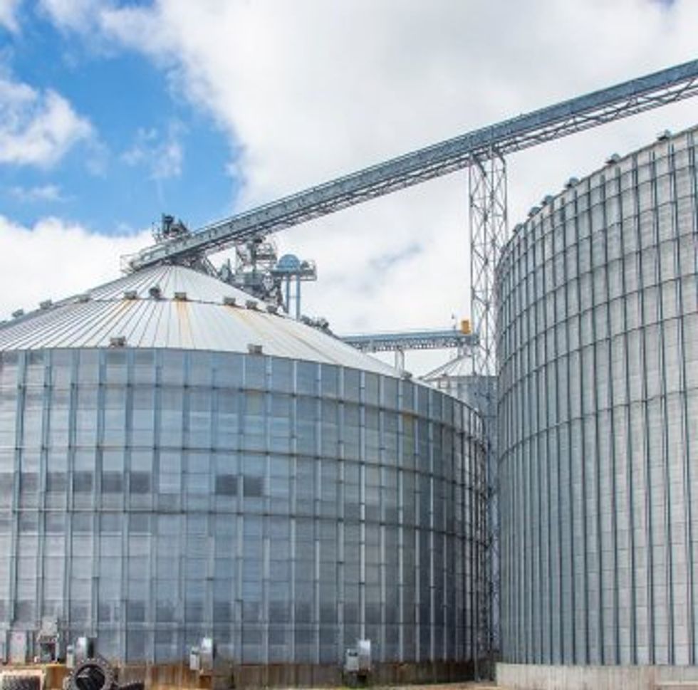
Specialized Industries

Interact With Our Compliance Experts

Upcoming Events


The U.S. Environmental Protection Agency (EPA or the Agency) is finalizing amendments to the National Emission Standards for Hazardous Air Pollutants (NESHAP) for Integrated Iron and Steel Manufacturing Facilities to regulate hazardous air pollutant (HAP) emissions. The amendments include: HAP from unmeasured fugitive and intermittent particulate (UFIP) sources previously not regulated by the NESHAP; previously unregulated HAP for sinter plants:; previously unregulated pollutants for blast furnace (BF) stoves and basic oxygen process furnaces (BOPFs) primary control devices; and previously unregulated pollutants for BF primary control devices. We are also finalizing an update to the technology review for this source category.
DATES: This final rule is effective June 3, 2024, published in the Federal Register April 3, 2024, page 23294 .
View final rule.
| §63.14 Incorporations by reference. | ||
| (i)(88), (i)(110), (o) | Revised | View text |
| (o)(3) | Added | View text |
| §63.7782 What parts of my plant does this subpart cover? | ||
| (c)-(e) | Revised | View text |
| §63.7783 When do I have to comply with this subpart? | ||
| (a) introductory text | Revised | View text |
| (g) | Added | View text |
| §63.7791 How do I comply with the requirements for the control of mercury from BOPF Groups? | ||
| Section heading | Revised | View text |
| §63.7792 What fenceline monitoring requirements must I meet? | ||
| Entire section | Added | View text |
| §63.7793 What work practice standards must I meet? | ||
| Entire section | Added | View text |
| §63.7800 What are my operation and maintenance requirements? | ||
| (b) introductory text | Revised | View text |
| (b)(8)-(9) | Added | View text |
| §63.7820 By what date must I conduct performance tests or other initial compliance demonstrations? | ||
| (e) | Revised | View text |
| §63.7821 When must I conduct subsequent performance tests? | ||
| Entire section | Revised | View text |
| §63.7823 What test methods and other procedures must I use to demonstrate initial compliance with the opacity limits? | ||
| (a) | Revised | View text |
| (c)(3), (d)(6), (f)-(h) | Added | View text |
| §63.7825 What test methods and other procedures must I use to demonstrate initial compliance with the emission limits for hazardous air pollutants? | ||
| Section heading | Revised | View text |
| (a) introductory text; (b)(1)(v), (b)(2), (c) | Revised | View text |
| (g)(-(k) | Added | View text |
| §63.7830 What are my monitoring requirements? | ||
| (e)(2) | Revised | View text |
| §63.7833 How do I demonstrate continuous compliance with the emission limitations that apply to me? | ||
| (j) | Added | View text |
| §63.7840 What notifications must I submit and when? | ||
| (g)(3), (h)(3) | Removed | View text |
| (i) | Added | View text |
| §63.7841 What reports must I submit and when? | ||
| (b)(14), (h) | Added | View text |
| (d) | Revised | View text |
| §63.7842 What records must I keep? | ||
| (d) | Revised | View text |
| (f), (g) | Added | View text |
| §63.7852 What definitions apply to this subpart? | ||
| Definitions for “Iron beaching operation”, Large blast furnace”, “Planned bleeder valve opening”, “Slip”, “Small blast furnace”, “Total hydrocarbons (THC)”, and “Unplanned bleeder valve opening” | Added | View text |
| Table 1 to Subpart FFFFF of Part 63 - Emission, Opacity, and Work Practice Limits | ||
| Entire table | Revised | View text |
| Table 2 to Subpart FFFFF of Part 63 - Initial Compliance With Emission and Opacity Limits | ||
| Entire table | Revised | View text |
| Table 3 to Subpart FFFFF of Part 63 - Continuous Compliance With Emission and Opacity Limits | ||
| Entire table | Revised | View text |
| Table 4 to Subpart FFFFF of Part 63 - Applicability of General Provisions to Subpart FFFFF | ||
| Entire table | Revised | View text |
| Table 5 to Subpart FFFFF of Part 63 - Toxic Equivalency Factors | ||
| Entire table | Added | View text |
| Table 6 to Subpart FFFFF of Part 63 - List of Polycyclic Aromatic Hydrocarbons | ||
| Entire table | Added | View text |
New Text
§63.14 Incorporations by reference.
* * * *
(i)(88) ASTM D6348-12 (Reapproved 2020), Determination of Gaseous Compounds by Extractive Direct Interface Fourier Transform (FTIR) Spectroscopy, including Annexes A1 through A8, Approved December 1; 2020, IBR approved for §§63.365(b); 63.7825(g) and (h) .
* * * * *
(i)(110) ASTM D7520-16, Standard Test Method for Determining the Opacity of a Plume in the Outdoor Ambient Atmosphere, approved April 1, 2016; IBR approved for §§63.1625(b); table 3 to subpart LLLLL; 63.7823(c) through (f), 63.7833(g); 63.11423(c).
* * * * *
(o) U.S. Environmental Protection Agency, 1200 Pennsylvania Avenue NW, Washington, DC 20460; phone: (202) 272-0167; website: www.epa.gov/aboutepa/forms/contact-epa .
§63.7782 What parts of my plant does this subpart cover?
* * * *
(c) This subpart covers emissions from the sinter plant windbox exhaust, discharge end, and sinter cooler; the blast furnace casthouse; the blast furnace stove; and the BOPF shop including each individual BOPF and shop ancillary operations (hot metal transfer, hot metal desulfurization, slag skimming, and ladle metallurgy). This subpart also covers fugitive and intermittent particulate emissions from blast furnace unplanned bleeder valve openings, blast furnace planned bleeder valve openings, blast furnace and BOPF slag processing, handling, and storage, blast furnace bell leaks, beaching of iron from blast furnaces, blast furnace casthouse fugitives, and BOPF shop fugitives.
(d) A sinter plant, blast furnace, blast furnace stove, or BOPF shop at your integrated iron and steel manufacturing facility is existing if you commenced construction or reconstruction of the affected source before July 13, 2001.
(e) A sinter plant, blast furnace, blast furnace stove, or BOPF shop at your integrated iron and steel manufacturing facility is new if you commence construction or reconstruction of the affected source on or after July 13, 2001. An affected source is reconstructed if it meets the definition of reconstruction in §63.2.
§63.7783 When do I have to comply with this subpart?
(a) If you have an existing affected source, you must comply with each emission limitation, standard, and operation and maintenance requirement in this subpart that applies to you by the dates specified in paragraphs (a)(1) and (2) of this section. This paragraph does not apply to the emission limitations for BOPF group: mercury (Hg); sinter plant windbox: Hg, hydrochloric acid (HCl), carbonyl sulfide (COS); Blast Furnace casthouse: HCl, total hydrocarbon (THC); Blast Furnace stove: HCl and total hydrocarbon (THC); primary emission control system for a BOPF: 2,3,7,8-tetrachlorodibenzo-p-dioxin (2,3,7,8-TCDD) toxic equivalent (TEQ), HCl, THC; fugitive and intermittent particulate sources.
* * * *
§63.7791 How do I comply with the requirements for the control of mercury from BOPF Groups?
* * * *
§63.7800 What are my operation and maintenance requirements?
* * * *
(b) You must prepare and operate at all times according to a written operation and maintenance plan for each capture system or control device subject to an operating limit in §63.7790(b). Each plan must address the elements in paragraphs (b)(1) through (9) of this section.
§63.7820 By what date must I conduct performance tests or other initial compliance demonstrations?
* * * *
(e) Notwithstanding the deadlines in this section, existing and new affected sources must comply with the deadlines for making the initial compliance demonstrations for the BOPF Group mercury emission limit set forth in paragraphs (e)(1) through (4) in this section.
§63.7821 When must I conduct subsequent performance tests?
(a) You must conduct subsequent performance tests to demonstrate compliance with all applicable emission and opacity limits in table 1 to this subpart at the frequencies specified in paragraphs (b) through (m) of this section.
(b) For each sinter cooler at an existing sinter plant and each emissions unit equipped with a control device other than a baghouse, you must conduct subsequent particulate matter and opacity performance tests no less frequently than twice (at mid-term and renewal) during each term of your title V operating permit.
(c) For each emissions unit equipped with a baghouse, you must conduct subsequent particulate matter and opacity performance tests no less frequently than once during each term of your title V operating permit.
(d) For sources without a title V operating permit, you must conduct subsequent particulate matter and opacity performance tests every 2.5 years.
(e) For each BOPF Group, if demonstrating compliance with the mercury emission limit in table 1 to this subpart through performance testing under §§63.7825 and 63.7833, you must conduct subsequent performance tests twice per permit cycle ( i.e., mid-term and initial/final) for sources with title V operating permits, and every 2.5 years for sources without a title V operating permit, at the outlet of the control devices for the BOPF Group.
(f) For each sinter plant windbox, you must conduct subsequent mercury, hydrogen chloride, carbonyl sulfide, dioxin/furan, and polycyclic aromatic hydrocarbon performance tests every 5 years.
(g) For each blast furnace stove and BOPF shop primary emission control device, you must conduct subsequent hydrogen chloride and total hydrocarbon testing every 5 years. For the BOPF shop primary emission control device, you must also conduct subsequent dioxin/furan testing every 5 years.
(h) For each blast furnace casthouse and BOPF shop, you must conduct subsequent opacity tests two times per month during a cast, or during a full heat cycle, as appropriate.
(i) For planned bleeder valve openings on each blast furnace, you must conduct opacity tests according to §63.7823(f) for each planned opening.
(j) For slag processing, handling, and storage operations for each blast furnace or BOPF, you must conduct subsequent opacity tests once per week for a minimum of 18 minutes for each: BF pit filling; BOPF slag pit filling; BF pit digging; BOPF slag pit digging; and one slag handling (either truck loading or dumping slag to slag piles).
(k) For large bells on each blast furnace, you must conduct visible emissions testing on the interbell relief valve according to EPA Method 22 in appendix A-7 to part 60 of this chapter, unless specified in paragraphs (k)(1) through (3) of this section. Testing must be conducted monthly, for 15 minutes.
(1) If visible emissions are detected for a large bell during the monthly visible emissions testing, you must conduct EPA Method 9 (in appendix A-4 to part 60 of this chapter) opacity tests in place of EPA Method 22 testing on that bell once per month, taking 3-minute averages for 15 minutes, until the large bell seal is repaired or replaced.
(2) If the average of 3 instantaneous visible emission readings taken while the interbell relief valve is exhausting exceeds 20 percent, you must initiate corrective action within five business days.
(3) Ten business days after the initial opacity exceedance of 20 percent, you must conduct an EPA Method 9 opacity test, taking 3-minute averages for 15 minutes. If the average of 3 instantaneous visible emissions readings from this test exceeds 20 percent, you must repair or replace that bell seal within 4 months.
(l) For small bells on each blast furnace, you must conduct visible emissions testing according to EPA Method 22 in appendix A-7 to part 60 of this chapter. Testing must be conducted monthly for 15 minutes. If visible emissions are observed, you must compare the period between the visible emissions being present and the most recent bell seal repair or replacement. If this time period or throughput is shorter or lower than the period or throughput stated in the O&M plan required by 63.7800, this new shorter period or lower limit shall be placed in the O&M plan as the work practice limit.
(m) For each blast furnace casthouse, you must conduct subsequent hydrogen chloride and total hydrocarbon testing every 5 years.
§63.7823 What test methods and other procedures must I use to demonstrate initial compliance with the opacity limits?
(a) For each discharge end of a sinter plant, sinter plant cooler, blast furnace casthouse, BOPF shop, and large bell on a blast furnace, you must conduct each performance test that applies to your affected source based on representative performance ( i.e., performance based on normal operating conditions) of the affected source for the period being tested, according to the conditions detailed in paragraphs (b) through (d) of this section. Representative conditions exclude periods of startup and shutdown. You shall not conduct performance tests during periods of malfunction. You must record the process information that is necessary to document operating conditions during the test and include in such record an explanation to support that such conditions represent normal operation. Upon request, you shall make available to the Administrator such records as may be necessary to determine the conditions of performance tests.
* * * *
§63.7825 What test methods and other procedures must I use to demonstrate initial compliance with the emission limits for hazardous air pollutants?
(a) If demonstrating compliance with the emission limits in Table 1 to this subpart through performance testing, you must conduct a performance test to demonstrate initial compliance with the emission limit. If demonstrating compliance with the emission limit through performance testing, you must conduct each performance test that applies to your affected source based on representative performance ( i.e., performance based on normal operating conditions) of the affected source for the period being tested, according to the conditions detailed in paragraphs (b) through (k) of this section. Representative conditions exclude periods of startup and shutdown. You shall not conduct performance tests during periods of malfunction. Initial compliance tests must be conducted by the deadlines in §63.7820(e).
* * * * *
(b) * * *
(1) * * *
(v) EPA Method 29 or 30B in appendix A-8 to part 60 of this chapter to determine the concentration of mercury from the exhaust stream stack of each unit. If performing measurements using EPA Method 29, you must collect a minimum sample volume of 1.7 dscm (60 dscf). Alternative test methods may be considered on a case-by-case basis per §63.7(f).
(2) Three valid test runs are needed to comprise a performance test of each unit in table 1 to this subpart as applicable. If the performance testing results for any of the emission points yields a non-detect value, then the method detection limit (MDL) must be used to calculate the mass emissions (lb) for that emission unit and, in turn, for calculating the sum of the emissions (in units of pounds of mercury per ton of steel scrap or pounds of mercury per ton of product sinter) for all units subject to the emission standard for determining compliance. If the resulting mercury emissions are greater than the MACT emission standard, the owner or operator may use procedures that produce lower MDL results and repeat the mercury performance testing one additional time for any emission point for which the measured result was below the MDL. If this additional testing is performed, the results from that testing must be used to determine compliance ( i.e., there are no additional opportunities allowed to lower the MDL).
* * * * *
(c) Calculate the mass emissions, based on the average of three test run values, for each BOPF Group unit (or combination of units that are ducted to a common stack and are tested when all affected sources are operating pursuant to paragraph (a) of this section) using equation 1 to this paragraph (c) as follows:
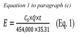
Where:
E = Mass emissions of pollutant, pounds (lb);
C s = Concentration of pollutant in stack gas, mg/dscm;
454,000 = Conversion factor (mg/lb);
Q = Volumetric flow rate of stack gas, dscf/min;
35.31 = Conversion factor (dscf/dscm); and
t = Duration of test, minutes.
* * * *
§63.7830 What are my monitoring requirements?
* * * *
(e)(2) Compute and record the 30-day rolling average of the volatile organic compound emissions (lbs/ton of sinter) for each operating day using the procedures in §63.7824(e).
§63.7841 What reports must I submit and when?
* * * *
(d) CEDRI submission. If you are required to submit reports following the procedure specified in this paragraph, you must submit reports to the EPA via CEDRI, which can be accessed through EPA's CDX ( https://cdx.epa.gov/ ). You must use the appropriate electronic report template on the CEDRI website ( https://www.epa.gov/electronic-reporting-air-emissions/compliance-and-emissions-data-reporting-interface-cedri ) for this subpart. The date report templates become available will be listed on the CEDRI website. The report must be submitted by the deadline specified in this subpart, regardless of the method in which the report is submitted. Do not use CEDRI to submit information you claim as CBI. Although we do not expect persons to assert a claim of CBI, if you wish to assert a CBI claim for some of the information in the report, you must submit a complete file, including information claimed to be CBI, to the EPA following the procedures in paragraphs (d)(1) and (2) of this section. Clearly mark the part or all of the informatioqn that you claim to be CBI. Information not marked as CBI may be authorized for public release without prior notice. Information marked as CBI will not be disclosed except in accordance with procedures set forth in 40 CFR part 2. All CBI claims must be asserted at the time of submission. Anything submitted using CEDRI cannot later be claimed CBI. Furthermore, under CAA section 114(c), emissions data is not entitled to confidential treatment, and the EPA is required to make emissions data available to the public. Thus, emissions data will not be protected as CBI and will be made publicly available. You must submit the same file submitted to the CBI office with the CBI omitted to the EPA via the EPA's CDX as described earlier in this paragraph.
(1) The preferred method to receive CBI is for it to be transmitted electronically using email attachments, File Transfer Protocol, or other online file sharing services. Electronic submissions must be transmitted directly to the OAQPS CBI Office at the email address oaqpscbi@epa.gov, and as described above, should include clear CBI markings and be flagged to the attention of the Integrated Iron and Steel Sector Lead. If assistance is needed with submitting large electronic files that exceed the file size limit for email attachments, and if you do not have your own file sharing service, please email oaqpscbi@epa.gov to request a file transfer link.
(2) If you cannot transmit the file electronically, you may send CBI information through the postal service to the following address: OAQPS Document Control Officer (C404-02), OAQPS, U.S. Environmental Protection Agency, Research Triangle Park, North Carolina 27711, Attention Integrated Iron and Steel Sector Lead. The mailed CBI material should be double wrapped and clearly marked. Any CBI markings should not show through the outer envelope.
§63.7842 What records must I keep?
* * * *
(d) You must keep the records required in §§63.7823, 63.7833, and 63.7834 to show continuous compliance with each emission limitation and operation and maintenance requirement that applies to you. This includes a record of each large and small bell repair and replacement, a record of the date on which the large bell opacity has exceeded 20 percent, and the most current time period or throughput over which no opacity was observed from the small bell.
Table 1 to Subpart FFFFF of Part 63 - Emission, Opacity, and Work Practice Limits
As required in §63.7790(a), you must comply with each applicable emission, opacity, and work practice limit in the following table:
| For . . . | You must comply with each of the following . . . |
|---|---|
| 1 This limit applies if the cooler is vented to the same control device as the discharge end. | |
| 2 This concentration limit (gr/dscf) for a control device does not apply to discharges inside a building or structure housing the discharge end at an existing sinter plant, inside a casthouse at an existing blast furnace, or inside an existing BOPF shop if the control device was installed before August 30, 2005. | |
| 3 This limit applies to control devices operated in parallel for a single BOPF during the oxygen blow. | |
| 1. Each windbox exhaust stream at an existing sinter plant | a. You must not cause to be discharged to the atmosphere any gases that contain particulate matter in excess of 0.4 lb/ton of product sinter; |
| b. You must not cause to be discharged to the atmosphere any gases that contain mercury in excess of 0.000018 lb/ton of product sinter; | |
| c. You must not cause to be discharged to the atmosphere any gases that contain hydrogen chloride in excess of 0.025 lb/ton of product sinter; | |
| d. You must not cause to be discharged to the atmosphere any gases that contain carbonyl sulfide in excess of 0.064 lb/ton of product sinter; | |
| e. You must not cause to be discharged to the atmosphere any gases that contain D/F TEQs in excess of 1.1E-08 lb/ton of product sinter; and | |
| f. You must not cause to be discharged to the atmosphere any gases that contain polycyclic aromatic hydrocarbons in excess of 0.0018 lb/ton of product sinter. | |
| 2. Each windbox exhaust stream at a new sinter plant | a. You must not cause to be discharged to the atmosphere any gases that contain particulate matter in excess of 0.3 lb/ton of product sinter; |
| b. You must not cause to be discharged to the atmosphere any gases that contain mercury in excess of 0.000012 lb/ton of product sinter; | |
| c. You must not cause to be discharged to the atmosphere any gases that contain hydrogen chloride in excess of 0.0012 lb/ton of product sinter; | |
| d. You must not cause to be discharged to the atmosphere any gases that contain carbonyl sulfide in excess of 0.030 lb/ton of product sinter; | |
| e. You must not cause to be discharged to the atmosphere any gases that contain D/F TEQs in excess of 1.1E-08 lb/ton of product sinter; and | |
| f. You must not cause to be discharged to the atmosphere any gases that contain polycyclic aromatic hydrocarbons in excess of 0.0015 lb/ton of product sinter. | |
| 3. Each discharge end at an existing sinter plant | a. You must not cause to be discharged to the atmosphere any gases that exit from one or more control devices that contain, on a flow-weighted basis, particulate matter in excess of 0.02 gr/dscf; 12 and |
| b. You must not cause to be discharged to the atmosphere any secondary emissions that exit any opening in the building or structure housing the discharge end that exhibit opacity greater than 20 percent (6-minute average). | |
| 4. Each discharge end at a new sinter plant | a. You must not cause to be discharged to the atmosphere any gases that exit from one or more control devices that contain, on a flow weighted basis, particulate matter in excess of 0.01 gr/dscf; and |
| b. You must not cause to be discharged to the atmosphere any secondary emissions that exit any opening in the building or structure housing the discharge end that exhibit opacity greater than 10 percent (6-minute average). | |
| 5. Each sinter cooler at an existing sinter plant | You must not cause to be discharged to the atmosphere any emissions that exhibit opacity greater than 10 percent (6-minute average). |
| 6. Each sinter cooler at a new sinter plant | You must not cause to be discharged to the atmosphere any gases that contain particulate matter in excess of 0.01 gr/dscf. |
| 7. Each casthouse at an existing blast furnace | a. You must not cause to be discharged to the atmosphere any gases that exit from a control device that contain particulate matter in excess of 0.01 gr/dscf; 2 |
| b. You must not cause to be discharged to the atmosphere any secondary emissions that exit all openings in the casthouse or structure housing the blast furnace that exhibit opacity greater than 20 percent (6-minute average); | |
| c. You must not cause to be discharged to the atmosphere any gases that exit from a control device that contain hydrogen chloride in excess of 0.0056 lb/ton of iron; | |
| d. You must not cause to be discharged to the atmosphere any gases that exit from a control device that contain total hydrocarbons as propane in excess of 0.48 lb/ton of iron; and | |
| e. You must not cause unplanned bleeder valve openings in excess of 4 events per year for large blast furnaces or 15 events per year for small blast furnaces. | |
| 8. Each casthouse at a new blast furnace | a. You must not cause to be discharged to the atmosphere any gases that exit from a control device that contain particulate matter in excess of 0.003 gr/dscf; and |
| b. You must not cause to be discharged to the atmosphere any secondary emissions that exit all openings in the casthouse or structure housing the blast furnace that exhibit opacity greater than 15 percent (6-minute average); | |
| c. You must not cause to be discharged to the atmosphere any gases that exit from a control device that contain hydrogen chloride in excess of 0.00059 lb/ton of iron; | |
| d. You must not cause to be discharged to the atmosphere any gases that exit from a control device that contain total hydrocarbons as propane in excess of 0.035 lb/ton of iron; and | |
| e. You must not cause unplanned bleeder valve openings in excess of zero events per year. | |
| 9. Each BOPF at a new or existing shop | a. You must not cause to be discharged to the atmosphere any gases that exit from a primary emission control system for a BOPF with a closed hood system at a new or existing BOPF shop that contain, on a flow-weighted basis, particulate matter in excess of 0.03 gr/dscf during the primary oxygen blow; 23 |
| b. You must not cause to be discharged to the atmosphere any gases that exit from a primary emission control system for a BOPF with an open hood system that contain, on a flow-weighted basis, particulate matter in excess of 0.02 gr/dscf during the steel production cycle for an existing BOPF shop 23 or 0.01 gr/dscf during the steel production cycle for a new BOPF shop; 3 | |
| c. You must not cause to be discharged to the atmosphere any gases that exit from a control device used solely for the collection of secondary emissions from the BOPF that contain particulate matter in excess of 0.01 gr/dscf for an existing BOPF shop 2 or 0.0052 gr/dscf for a new BOPF shop; | |
| d. You must not cause to be discharged to the atmosphere any gases that exit from a primary emission control system for a BOPF that contain hydrogen chloride in excess of 0.058 lb/ton of steel for existing sources and 2.8E-04 lb/ton steel for new sources; | |
| e. You must not cause to be discharged to the atmosphere any gases that exit from a primary emission control system for a BOPF that contain THC as propane in excess of 0.04 lb/ton of steel for existing sources and 0.0017 lb/ton of steel for new sources; and | |
| f. You must not cause to be discharged to the atmosphere any gases that exit from a primary emission control system for a BOPF that contain D/F TEQs in excess of 9.2E-10 lb/ton of steel. | |
| 10. Each hot metal transfer, skimming, and desulfurization operation at a new or existing BOPF shop | You must not cause to be discharged to the atmosphere any gases that exit from a control device that contain particulate matter in excess of 0.01 gr/dscf for an existing BOPF shop 2 or 0.003 gr/dscf for a new BOPF shop. |
| 11. Each ladle metallurgy operation at a new or existing BOPF shop | You must not cause to be discharged to the atmosphere any gases that exit from a control device that contain particulate matter in excess of 0.01 gr/dscf for an existing BOPF shop 2 or 0.004 gr/dscf for a new BOPF shop. |
| 12. Each existing BOPF shop | You must not cause to be discharged to the atmosphere any secondary emissions that exit any opening in the BOPF shop or any other building housing the BOPF or BOPF shop operation that exhibit opacity greater than 20 percent (3-minute average). |
| 13. Each new BOPF shop | a. You must not cause to be discharged to the atmosphere any secondary emissions that exit any opening in the BOPF shop or other building housing a bottom-blown BOPF or BOPF shop operations that exhibit opacity (for any set of 6-minute averages) greater than 10 percent, except that one 6-minute period not to exceed 20 percent may occur once per steel production cycle; or |
| b. You must not cause to be discharged to the atmosphere any secondary emissions that exit any opening in the BOPF shop or other building housing a top-blown BOPF or BOPF shop operations that exhibit opacity (for any set of 3-minute averages) greater than 10 percent, except that one 3-minute period greater than 10 percent but less than 20 percent may occur once per steel production cycle. | |
| 14. Each BOPF Group at an existing BOPF shop | You must not cause to be discharged to the atmosphere any gases that exit from the collection of BOPF Group control devices that contain mercury in excess of 0.00026 lb/ton of steel scrap input to the BOPF. |
| 15. Each BOPF Group at a new BOPF shop | You must not cause to be discharged to the atmosphere any gases that exit from the collection of BOPF Group control devices that contain mercury in excess of 0.000081 lb/ton of steel scrap input to the BOPF. |
| 16. Each planned bleeder valve opening at a new or existing blast furnace | You must not cause to be discharged to the atmosphere any emissions that exhibit opacity greater than 8 percent (6-minute average). |
| 17. Each slag processing, handling and storage operation for a new or existing blast furnace or BOPF | You must not cause to be discharged to the atmosphere any emissions that exhibit opacity greater than 10 percent (6-minute average). |
| 18. Each existing blast furnace stove | a. You must not cause to be discharged to the atmosphere any gases that exit from a control device that contain HCl in excess of 0.0012 lb/MMBtu; and |
| b. You must not cause to be discharged to the atmosphere any gases that exit from a control device that contain THC in excess of 0.12 lb/MMBtu. | |
| 19. Each new blast furnace stove | a. You must not cause to be discharged to the atmosphere any gases that exit from a control device that contain HCl in excess of 4.2e-4 lb/MMBtu; and |
| b. You must not cause to be discharged to the atmosphere any gases that exit from a control device that contain THC in excess of 0.0054 lb/MMBtu. | |
Table 2 to Subpart FFFFF of Part 63 - Initial Compliance With Emission and Opacity Limits
As required in §63.7826(a)(1), you must demonstrate initial compliance with the emission and opacity limits according to the following table:
| For . . . | You have demonstrated initial compliance if . . . |
|---|---|
| 1. Each windbox exhaust stream at an existing sinter plant | a. The process-weighted mass rate of particulate matter from a windbox exhaust stream, measured according to the performance test procedures in §63.7822(c), did not exceed 0.4 lb/ton of product sinter; |
| b. The process-weighted mass rate of mercury from a windbox exhaust stream, measured according to the performance test procedures in §63.7825, did not exceed 0.000018 lb/ton of product sinter; | |
| c. The process-weighted mass rate of hydrogen chloride from a windbox exhaust stream, measured according to the performance test procedures in §63.7825, did not exceed 0.025 lb/ton of product sinter; | |
| d. The process-weighted mass rate of carbonyl sulfide from a windbox exhaust stream, measured according to the performance test procedures in §63.7825, did not exceed 0.064 lb/ton of product sinter; | |
| e. The process-weighted mass rate of D/F TEQs from a windbox exhaust stream, measured according to the performance test procedures in §63.7825, did not exceed 1.1E-08 lb/ton of product sinter; and | |
| f. The process-weighted mass rate of polycyclic aromatic hydrocarbons from a windbox exhaust stream, measured according to the performance test procedures in §63.7825, did not exceed 0.0018 lb/ton of product sinter. | |
| 2. Each windbox exhaust stream at a new sinter plant | a. The process-weighted mass rate of particulate matter from a windbox exhaust stream, measured according to the performance test procedures in §63.7822(c), did not exceed 0.3 lb/ton of product sinter; |
| b. The process-weighted mass rate of mercury from a windbox exhaust stream, measured according to the performance test procedures in §63.7825, did not exceed 0.000012 lb/ton of product sinter; | |
| c. The process-weighted mass rate of hydrogen chloride from a windbox exhaust stream, measured according to the performance test procedures in §63.7825, did not exceed 0.0012 lb/ton of product sinter; | |
| d. The process-weighted mass rate of carbonyl sulfide from a windbox exhaust stream, measured according to the performance test procedures in §63.7825, did not exceed 0.030 lb/ton of product sinter; | |
| e. The process-weighted mass rate of D/F TEQs from a windbox exhaust stream, measured according to the performance test procedures in §63.7825, did not exceed 1.1E-08 lb/ton of product sinter; and | |
| f. The process-weighted mass rate of polycyclic aromatic hydrocarbons from a windbox exhaust stream, measured according to the performance test procedures in §63.7825, did not exceed 0.0015 lb/ton of product sinter. | |
| 3. Each discharge end at an existing sinter plant | a. The flow-weighted average concentration of particulate matter from one or more control devices applied to emissions from a discharge end, measured according to the performance test procedures in §63.7822(d), did not exceed 0.02 gr/dscf; and |
| b. The opacity of secondary emissions from each discharge end, determined according to the performance test procedures in §63.7823(c), did not exceed 20 percent (6-minute average). | |
| 4. Each discharge end at a new sinter plant | a. The flow-weighted average concentration of particulate matter from one or more control devices applied to emissions from a discharge end, measured according to the performance test procedures in §63.7822(d), did not exceed 0.01 gr/dscf; and |
| b. The opacity of secondary emissions from each discharge end, determined according to the performance test procedures in §63.7823(c), did not exceed 10 percent (6-minute average). | |
| 5. Each sinter cooler at an existing sinter plant | The opacity of emissions, determined according to the performance test procedures in §63.7823(e), did not exceed 10 percent (6-minute average). |
| 6. Each sinter cooler at a new sinter plant | The average concentration of particulate matter, measured according to the performance test procedures in §63.7822(b), did not exceed 0.01 gr/dscf. |
| 7. Each casthouse at an existing blast furnace | a. The average concentration of particulate matter from a control device applied to emissions from a casthouse, measured according to the performance test procedures in §63.7822(e), did not exceed 0.01 gr/dscf; |
| b. The opacity of secondary emissions from each casthouse, determined according to the performance test procedures in §63.7823(c), did not exceed 20 percent (6-minute average); | |
| c. The process-weighted mass rate of hydrogen chloride from a windbox exhaust stream, measured according to the performance test procedures in §63.7825, did not exceed 0.0056 lb/ton of iron; | |
| d. The process-weighted mass rate of total hydrocarbons from a windbox exhaust stream, measured according to the performance test procedures in §63.7825, did not exceed 0.48 lb/ton of iron; and | |
| e. The number of unplanned bleeder valve openings in one year, as reported according to the specifications in §63.7841(b)(14), did not exceed 4 events for large blast furnaces or 15 events for small blast furnaces. | |
| 8. Each casthouse at a new blast furnace | a. The average concentration of particulate matter from a control device applied to emissions from a casthouse, measured according to the performance test procedures in §63.7822(e), did not exceed 0.003 gr/dscf; and |
| b. The opacity of secondary emissions from each casthouse, determined according to the performance test procedures in §63.7823(c), did not exceed 15 percent (6-minute average); | |
| c. The process-weighted mass rate of hydrogen chloride from a windbox exhaust stream, measured according to the performance test procedures in §63.7825, did not exceed 0.00059 lb/ton of iron; | |
| d. The process-weighted mass rate of total hydrocarbons from a windbox exhaust stream, measured according to the performance test procedures in §63.7825, did not exceed 0.035 lb/ton of iron; and | |
| e. The number of unplanned bleeder valve openings in one year, as reported according to the specifications in §63.7841(b)(14), did not exceed zero events. | |
| 9. Each BOPF at a new or existing BOPF shop | a. The average concentration of particulate matter from a primary emission control system applied to emissions from a BOPF with a closed hood system, measured according to the performance test procedures in §63.7822(f), did not exceed 0.03 gr/dscf for a new or existing BOPF shop; |
| b. The average concentration of particulate matter from a primary emission control system applied to emissions from a BOPF with an open hood system, measured according to the performance test procedures in §63.7822(g), did not exceed 0.02 gr/dscf for an existing BOPF shop or 0.01 gr/dscf for a new BOPF shop; | |
| c. The average concentration of particulate matter from a control device applied solely to secondary emissions from a BOPF, measured according to the performance test procedures in §63.7822(g), did not exceed 0.01 gr/dscf for an existing BOPF shop or 0.0052 gr/dscf for a new BOPF shop; | |
| d. The process-weighted mass rate of hydrogen chloride from a windbox exhaust stream, measured according to the performance test procedures in §63.7825, did not exceed 0.058 lb/ton of steel for an existing BOPF shop or 0.00028 lb/ton of steel for a new BOPF shop; | |
| e. The process-weighted mass rate of total hydrocarbons from a windbox exhaust stream, measured according to the performance test procedures in §63.7825, did not exceed 0.04 lb/ton of steel for an existing BOPF shop or 0.0017 lb/ton of steel for a new BOPF shop; and | |
| f. The process-weighted mass rate of D/F TEQs from a windbox exhaust stream, measured according to the performance test procedures in §63.7825, did not exceed 9.2e-10 lb/ton of steel. | |
| 10. Each hot metal transfer skimming, and desulfurization at a new or existing BOPF shop | The average concentration of particulate matter from a control device applied to emissions from hot metal transfer, skimming, or desulfurization, measured according to the performance test procedures in §63.7822(h), did not exceed 0.01 gr/dscf for an existing BOPF shop or 0.003 gr/dscf for a new BOPF shop. |
| 11. Each ladle metallurgy operation at a new or existing BOPF shop | The average concentration of particulate matter from a control device applied to emissions from a ladle metallurgy operation, measured according to the performance test procedures in §63.7822(h), did not exceed 0.01 gr/dscf for an existing BOPF shop or 0.004 gr/dscf for a new BOPF shop. |
| 12. Each existing BOPF shop | The opacity of secondary emissions from each BOPF shop, determined according to the performance test procedures in §63.7823(d), did not exceed 20 percent (3-minute average). |
| 13. Each new BOPF shop | a. The opacity of the highest set of 6-minute averages from each BOPF shop housing a bottom-blown BOPF, determined according to the performance test procedures in §63.7823(d), did not exceed 20 percent and the second highest set of 6-minute averages did not exceed 10 percent; or |
| b. The opacity of the highest set of 3-minute averages from each BOPF shop housing a top-blown BOPF, determined according to the performance test procedures in §63.7823(d), did not exceed 20 percent and the second highest set of 3-minute averages did not exceed 10 percent. | |
| 14. Each BOPF Group at an existing BOPF shop | If demonstrating compliance through performance testing, the average emissions of mercury from the collection of BOPF Group control devices applied to the emissions from the BOPF Group, measured according to the performance test procedures in §63.7825, did not exceed 0.00026 lb/ton steel scrap input to the BOPF. |
| 15. Each BOPF Group at a new BOPF shop | If demonstrating compliance through performance testing, the average emissions of mercury from the collection of BOPF Group control devices applied to the emissions from the BOPF Group, measured according to the performance test procedures in §63.7825, did not exceed 0.000081 lb/ton steel scrap input to the BOPF. |
| 16. Each planned bleeder valve opening at a new or existing blast furnace | The opacity of emissions, determined according to the performance test procedures in §63.7823(f), did not exceed 8 percent (6-minute average). |
| 17. Each slag processing, handling and storage operation for a new or existing blast furnace or BOPF | The opacity of emissions, determined according to the performance test procedures in §63.7823(g), did not exceed 10 percent (6-minute average). |
| 18. Each existing blast furnace stove | a. The process-weighted mass rate of HCl from a windbox exhaust stream, measured according to the performance test procedures in §63.7825, did not exceed 0.0012 lb/MMBtu; and |
| b. The process-weighted mass rate of THC from a windbox exhaust stream, measured according to the performance test procedures in §63.7825, did not exceed 0.12 lb/MMBtu. | |
| 19. Each new blast furnace stove | a. The process-weighted mass rate of HCl from a windbox exhaust stream, measured according to the performance test procedures in §63.7825, did not exceed 4.2e-4 lb/MMBtu; and |
| b. The process-weighted mass rate of THC from a windbox exhaust stream, measured according to the performance test procedures in §63.7825, did not exceed 0.0054 lb/MMBtu. |
Table 3 to Subpart FFFFF of Part 63 - Continuous Compliance With Emission and Opacity Limits
As required in §63.7833(a), you must demonstrate continuous compliance with the emission and opacity limits according to the following table:
| For . . . | You must demonstrate continuous compliance by . . . |
|---|---|
| 1. Each windbox exhaust stream at an existing sinter plant | a. Maintaining emissions of particulate matter at or below 0.4 lb/ton of product sinter; b. Conducting subsequent performance tests at the frequencies specified in §63.7821; |
| c. Maintaining emissions of mercury at or below 0.000018 lb/ton of product sinter; | |
| d. Maintaining emissions of hydrogen chloride at or below 0.025 lb/ton of product sinter; | |
| e. Maintaining emissions of carbonyl sulfide at or below 0.064 lb/ton of product sinter; | |
| f. Maintaining emissions of D/F TEQs at or below 1.1E-08 lb/ton of product sinter; and | |
| g. Maintaining emissions of polycyclic aromatic hydrocarbons at or below 0.0018 lb/ton of product sinter. | |
| 2. Each windbox exhaust stream at a new sinter plant | a. Maintaining emissions of particulate matter at or below 0.3 lb/ton of product sinter; b. Conducting subsequent performance tests at the frequencies specified in §63.7821; |
| c. Maintaining emissions of mercury at or below 0.000012 lb/ton of product sinter; | |
| d. Maintaining emissions of hydrogen chloride at or below 0.0012 lb/ton of product sinter; | |
| e. Maintaining emissions of carbonyl sulfide at or below 0.030 lb/ton of product sinter; | |
| f. Maintaining emissions of D/F TEQs at or below 1.1E-08 lb/ton of product sinter; and | |
| g. Maintaining emissions of polycyclic aromatic hydrocarbons at or below 0.0015 lb/ton of product sinter. | |
| 3. Each discharge end at an existing sinter plant | a. Maintaining emissions of particulate matter from one or more control devices at or below 0.02 gr/dscf; and b. Maintaining the opacity of secondary emissions that exit any opening in the building or structure housing the discharge end at or below 20 percent (6-minute average); and |
| c. Conducting subsequent performance tests at the frequencies specified in §63.7821. | |
| 4. Each discharge end at a new sinter plant | a. Maintaining emissions of particulate matter from one or more control devices at or below 0.01 gr/dscf; and b. Maintaining the opacity of secondary emissions that exit any opening in the building or structure housing the discharge end at or below 10 percent (6-minute average); and |
| c. Conducting subsequent performance tests at the frequencies specified in §63.7821. | |
| 5. Each sinter cooler at an existing sinter plant | a. Maintaining the opacity of emissions that exit any sinter cooler at or below 10 percent (6-minute average); and b. Conducting subsequent performance tests at the frequencies specified in §63.7821. |
| 6. Each sinter cooler at a new sinter plant | a. Maintaining emissions of particulate matter at or below 0.1 gr/dscf; and |
| b. Conducting subsequent performance tests at the frequencies specified in §63.7821. | |
| 7. Each casthouse at an existing blast furnace | a. Maintaining emissions of particulate matter from a control device at or below 0.01 gr/dscf; b. Maintaining the opacity of secondary emissions that exit all openings in the casthouse or structure housing the casthouse at or below 20 percent (6-minute average); |
| c. Conducting subsequent performance tests at the frequencies specified in §63.7821; | |
| d. Maintaining emissions of hydrogen chloride at or below 0.0056 lb/ton of iron; | |
| e. Maintaining emissions of total hydrocarbons at or below 0.48 lb/ton of iron; and | |
| f. Maintaining unplanned bleeder valve openings at or below 4 events per year for large blast furnaces or 15 events per year for small blast furnaces. | |
| 8. Each casthouse at a new blast furnace | a. Maintaining emissions of particulate matter from a control device at or below 0.003 gr/dscf; b. Maintaining the opacity of secondary emissions that exit all openings in the casthouse or structure housing the casthouse at or below 15 percent (6-minute average); |
| c. Conducting subsequent performance tests at the frequencies specified in §63.7821; | |
| d. Maintaining emissions of hydrogen chloride at or below 0.00059 lb/ton of iron; | |
| e. Maintaining emissions of total hydrocarbons at or below 0.035 lb/ton of iron; and | |
| f. Maintaining unplanned bleeder valve openings at zero events per year. | |
| 9. Each BOPF at a new or existing BOPF shop | a. Maintaining emissions of particulate matter from the primary control system for a BOPF with a closed hood system at or below 0.03 gr/dscf; |
| b. Maintaining emissions of particulate matter from the primary control system for a BOPF with an open hood system at or below 0.02 gr/dscf for an existing BOPF shop or 0.01 gr/dscf for a new BOPF shop; | |
| c. Maintaining emissions of particulate matter from a control device applied solely to secondary emissions from a BOPF at or below 0.01 gr/dscf for an existing BOPF shop or 0.0052 gr/dscf for a new BOPF shop; | |
| d. Conducting subsequent performance tests at the frequencies specified in §63.7821; | |
| e. Maintaining emissions of hydrogen chloride from a primary emission control system for a BOPF at or below 0.058 lb/ton of steel for existing sources and 2.8E-04 lb/ton steel for new sources; | |
| f. Maintaining emissions of THC from a primary emission control system for a BOPF at or below 0.04 lb/ton of steel for existing sources and 0.0017 lb/ton of steel for new sources; and | |
| g. Maintaining emissions of D/F TEQs from a primary emission control system for a BOPF at or below 9.2E-10 lb/ton of steel. | |
| 10. Each hot metal transfer, skimming, and desulfurization operation at a new or existing BOPF shop | a. Maintaining emissions of particulate matter from a control device at or below 0.01 gr/dscf at an existing BOPF or 0.003 gr/dscf for a new BOPF; and b. Conducting subsequent performance tests at the frequencies specified in §63.7821. |
| 11. Each ladle metallurgy operation at a new or existing BOPF shop | a. Maintaining emissions of particulate matter from a control device at or below 0.01 gr/dscf at an existing BOPF shop or 0.004 gr/dscf for a new BOPF shop; and |
| b. Conducting subsequent performance tests at the frequencies specified in §63.7821. | |
| 12. Each existing BOPF shop | a. Maintaining the opacity of secondary emissions that exit any opening in the BOPF shop or other building housing the BOPF shop or shop operation at or below 20 percent (3-minute average); and |
| b. Conducting subsequent performance tests at the frequencies specified in §63.7821. | |
| 13. Each new BOPF shop | a. Maintaining the opacity (for any set of 6-minute averages) of secondary emissions that exit any opening in the BOPF shop or other building housing a bottom-blown BOPF or shop operation at or below 10 percent, except that one 6-minute period greater than 10 percent but no more than 20 percent may occur once per steel production cycle; |
| b. Maintaining the opacity (for any set of 3-minute averages) of secondary emissions that exit any opening in the BOPF shop or other building housing a top-blown BOPF or shop operation at or below 10 percent, except that one 3-minute period greater than 10 percent but less than 20 percent may occur once per steel production cycle; and | |
| c. Conducting subsequent performance tests at the frequencies specified in §63.7821. | |
| 14. Each BOPF Group at an existing BOPF shop | a. Maintaining emissions of mercury from the collection of BOPF Group control devices at or below 0.00026 lb/ton steel scrap input to the BOPF; and |
| b. If demonstrating compliance through performance testing, conducting subsequent performance tests at the frequencies specified in §63.7821; and | |
| c. If demonstrating compliance through §63.7791(c), (d), or (e), maintaining records pursuant to §63.7842(e). | |
| 15. Each BOPF Group at a new BOPF shop | a. Maintaining emissions of mercury from the collection of BOPF Group control devices at or below 0.000081 lb/ton steel scrap input to the BOPF; and |
| b. If demonstrating compliance through performance testing, conducting subsequent performance tests at the frequencies specified in §63.7821; and | |
| c. If demonstrating compliance through §63.7791(c), (d), or (e), maintaining records pursuant to §63.7842(e). | |
| 16. Each planned bleeder valve opening at a new or existing blast furnace | a. Maintaining the opacity of emissions that exit any bleeder valve as a result of a planned opening at or below 8 percent (6-minute average); and |
| b. Conducting subsequent performance tests at the frequencies specified in §63.7821. | |
| 17. Each slag processing, handling and storage operation for a new or existing blast furnace or BOPF | a. Maintaining the opacity of emissions that exit any slag processing, handling, or storage operation at or below 10 percent (6-minute average); and b. Conducting subsequent performance tests at the frequencies specified in §63.7821. |
| 18. Each existing blast furnace stove | a. Maintaining emissions of HCl at or below 0.0012 lb/MMBtu; |
| b. Maintaining emissions of THC at or below 0.12 lb/MMBtu; and | |
| c. Conducting subsequent performance tests at the frequencies specified in §63.7821. | |
| 19. Each new blast furnace stove | a. Maintaining emissions of HCl at or below 4.2e-4 lb/MMBtu; |
| b. Maintaining emissions of THC at or below 0.0054 lb/MMBtu; and | |
| c. Conducting subsequent performance tests at the frequencies specified in §63.7821. |
Table 4 to Subpart FFFFF of Part 63 - Applicability of General Provisions to Subpart FFFFF
As required in §63.7850, you must comply with the requirements of the NESHAP General Provisions (subpart A of this part) shown in the following table:
| Citation | Subject | Applies to subpart FFFFF | Explanation |
|---|---|---|---|
| §63.1 | Applicability | Yes | |
| §63.2 | Definitions | Yes | |
| §63.3 | Units and Abbreviations | Yes | |
| §63.4 | Prohibited Activities | Yes | |
| §63.5 | Construction/Reconstruction | Yes | |
| §63.6(a), (b), (c), (d), (e)(1)(iii), (f)(2)-(3), (g), (h)(2)(ii)-(h)(9) | Compliance with Standards and Maintenance Requirements | Yes | |
| §63.6(e)(1)(i) | General Duty to Minimize Emissions | No, for new or reconstructed sources which commenced construction or reconstruction after August 16, 2019. For all other affected sources, Yes on or before January 11, 2021, and No thereafter | See §63.7810(d) for general duty requirement. |
| §63.6(e)(1)(ii) | Requirement to Correct Malfunctions ASAP | No, for new or reconstructed sources which commenced construction or reconstruction after August 16, 2019. For all other affected sources, Yes, on or before January 11, 2021, and No thereafter | |
| §63.6(e)(3) | SSM Plan Requirements | No, for new or reconstructed sources which commenced construction or reconstruction after August 16, 2019. For all other affected sources, Yes on or before January 11, 2021, and No thereafter | See §63.7810(c). |
| §63.6(f)(1) | Compliance except during SSM | No | See §63.7810(a). |
| §63.6(h)(1) | Compliance except during SSM | No | See §63.7810(a). |
| §63.6(h)(2)(i) | Determining Compliance with Opacity and VE Standards | No | Subpart FFFFF specifies methods and procedures for determining compliance with opacity emission and operating limits. |
| §63.6(i) | Extension of Compliance with Emission Standards | Yes | |
| §63.6(j) | Exemption from Compliance with Emission Standards | Yes | |
| §63.7(a)(1)-(2) | Applicability and Performance Test Dates | No | Subpart FFFFF and specifies performance test applicability and dates. |
| §63.7(a)(3), (b)-(d), (e)(2)-(4), (f)-(h) | Performance Testing Requirements | Yes | |
| §63.7(e)(1) | Performance Testing | No, for new or reconstructed sources which commenced construction or reconstruction after August 16, 2019. For all other affected sources, Yes on or before January 11, 2021, and No thereafter | See §§63.7822(a), 63.7823(a), and 63.7825(a). |
| §63.8(a)(1)-(3), (b), (c)(1)(ii), (c)(2)-(3), (c)(4)(i)-(ii), (c)(5)-(6), (c)(7)-(8), (d)(1)-(2), (e), (f)(1)-(5), (g)(1)-(4) | Monitoring Requirements | Yes | CMS requirements in §63.8(c)(4)(i)-(ii), (c)(5)-(6), (d)(1)-(2), and (e) apply only to COMS. |
| §63.8(a)(4) | Additional Monitoring Requirements for Control Devices in §63.11 | No | Subpart FFFFF does not require flares. |
| §63.8(c)(1)(i) | General Duty to Minimize Emissions and CMS Operation | No, for new or reconstructed sources which commenced construction or reconstruction after August 16, 2019. For all other affected sources, Yes on or before January 11, 2021, and No thereafter | |
| §63.8(c)(1)(iii) | Requirement to Develop SSM Plan for CMS | No, for new or reconstructed sources which commenced construction or reconstruction after August 16, 2019. For all other affected sources, Yes on or before January 11, 2021, and No thereafter | |
| §63.8(c)(4) | Continuous Monitoring System Requirements | No | Subpart FFFFF specifies requirements for operation of CMS. |
| §63.8(d)(3) | Written procedures for CMS | No, for new or reconstructed sources which commenced construction or reconstruction after August 16, 2019. For all other affected sources, Yes on or before January 11, 2021, and No thereafter | See §63.7842(b)(3). |
| §63.8(f)(6) | RATA Alternative | No | |
| §63.8(g)(5) | Data Reduction | No | Subpart FFFFF specifies data reduction requirements. |
| §63.9 | Notification Requirements | Yes | Additional notifications for CMS in §63.9(g) apply only to COMS. |
| §63.10(a), (b)(1), (b)(2)(x), (b)(2)(xiv), (b)(3), (c)(1)-(6), (c)(9)-(14), (d)(1)-(4), (e)(1)-(2), (e)(4), (f) | Recordkeeping and Reporting Requirements | Yes | Additional records for CMS in §63.10(c)(1)-(6), (9)-(14), and reports in §63.10(d)(1)-(2) apply only to COMS. |
| §63.10(b)(2)(i) | Recordkeeping of Occurrence and Duration of Startups and Shutdowns | No, for new or reconstructed sources which commenced construction or reconstruction after August 16, 2019. For all other affected sources, Yes on or before January 11, 2021, and No thereafter | |
| §63.10(b)(2)(ii) | Recordkeeping of Failures to Meet a Standard | No, for new or reconstructed sources which commenced construction or reconstruction after August 16, 2019. For all other affected sources, Yes on or before January 11, 2021, and No thereafter | See §63.7842(a)(2)-(4) for recordkeeping of (1) date, time, and duration of failure to meet the standard; (2) listing of affected source or equipment, and an estimate of the quantity of each regulated pollutant emitted over the standard; and (3) actions to minimize emissions and correct the failure. |
| §63.10(b)(2)(iii) | Maintenance Records | Yes | |
| §63.10(b)(2)(iv) | Actions Taken to Minimize Emissions During SSM | No, for new or reconstructed sources which commenced construction or reconstruction after August 16, 2019. For all other affected sources, Yes on or before January 11, 2021, and No thereafter | See §63.7842(a)(4) for records of actions taken to minimize emissions. |
| §63.10(b)(2)(v) | Actions Taken to Minimize Emissions During SSM | No, for new or reconstructed sources which commenced construction or reconstruction after August 16, 2019. For all other affected sources, Yes on or before January 11, 2021, and No thereafter | See §63.7842(a)(4) for records of actions taken to minimize emissions. |
| §63.10(b)(2)(vi) | Recordkeeping for CMS Malfunctions | Yes | |
| §63.10(b)(2)(vii)-(ix) | Other CMS Requirements | Yes | |
| §63.10(b)(2)(xiii) | CMS Records for RATA Alternative | No | |
| §63.10(c)(7)-(8) | Records of Excess Emissions and Parameter Monitoring Exceedances for CMS | No | Subpart FFFFF specifies record requirements; see §63.7842. |
| §63.10(c)(15) | Use of SSM Plan | No, for new or reconstructed sources which commenced construction or reconstruction after August 16, 2019. For all other affected sources, Yes on or before January 11, 2021, and No thereafter | |
| §63.10(d)(5)(i) | Periodic SSM Reports | No, for new or reconstructed sources which commenced construction or reconstruction after August 16, 2019. For all other affected sources, Yes on or before January 11, 2021, and No thereafter | See §63.7841(b)(4) for malfunction reporting requirements. |
| §63.10(d)(5)(ii) | Immediate SSM Reports | No, for new or reconstructed sources which commenced construction or reconstruction after August 16, 2019. For all other affected sources, Yes on or before January 11, 2021, and No thereafter | |
| §63.10(e)(3) | Excess Emission Reports | No | Subpart FFFFF specifies reporting requirements; see §63.7841. |
| §63.11 | Control Device Requirements | No | Subpart FFFFF does not require flares. |
| §63.12 | State Authority and Delegations | Yes | |
| §63.13-§63.16 | Addresses, Incorporations by Reference, Availability of Information and Confidentiality, Performance Track Provisions | Yes |


The Environmental Protection Agency (EPA) is finalizing amendments to the 2018 final rule that established fees for the administration of the Toxic Substances Control Act (TSCA). Specifically, EPA is finalizing changes to the fee amounts and EPA's total costs for administering TSCA; exemptions for entities subject to the EPA-initiated risk evaluation fees; exemptions for test rule fee activities; modifications to the self-identification and reporting requirements of EPA-initiated risk evaluation and test rule fees; modifications to EPA's proposed methodology for the production-volume-based fee allocation for EPA-initiated risk evaluation fees in any scenario in which a consortium is not formed; expanded fee requirements to companies required to submit information for test orders; modifications to the fee payment obligations of processors subject to test orders and enforceable consent agreements (ECA); and extended timeframes for certain fee payments and notices.
DATES: This rule is effective on April 22, 2024, published in the Federal Register February 21, 2024, page 12961.
View final rule.
| §700.43 Definitions applicable to this subpart. | ||
| Definitions of “Production volume” and “Small quantities solely for research and development.” | Added | View text |
| §700.45 Fee payments | ||
| (a)(2), (3) | Revised | View text |
| (b)(5), (7) | Revised | View text |
| (b)(10) | Added | View text |
| (c)-(d) | Revised | View text |
| (f)(2)(i) | Revised | View text |
| (f)(3)(i) | Revised | View text |
| (f)(4)-(5) | Revised | View text |
| (f)(6) | Added | View text |
| (g)(3)(i) | Revised | View text |
| (g)(3)(iv) | Revised | View text |
| (g)(5), (6) | Revised | View text |
New Text
§700.45 Fee payments
(a)* * *
(2) Manufacturers and processors of chemical substances and mixtures required to submit information for these chemical substances and mixtures under a TSCA section 4(a) test order or enforceable consent agreement, or manufacturers of chemical substances and mixtures required to submit information for these chemical substance and mixtures under a TSCA section 4(a) test rule, shall remit for each such test rule, order, or enforceable consent agreement the applicable fee identified in paragraph (c) of this section in accordance with the procedures in paragraphs (f) and (g) of this section. Manufacturers of a chemical substance subject to a test rule under TSCA section 4(a) are exempted from fee payment requirements in this section, if they meet one or more of the exemptions under this paragraphs (a)(2)(i) through (v) of this section on or after the certification cutoff date identified in paragraph (b)(6) of this section and do not conduct manufacturing outside of those exemptions after the certification cutoff dates or if they meet the exemptions under paragraph (a)(2)(vi) of this section for the five-year period preceding publication of the preliminary list and do not conduct manufacturing outside of that exemption during the five-year period preceding publication of the preliminary list; and the exemptions are only available if the manufacturer will meet one or more of the exemptions in this paragraph (a)(2)(i) through (vi) in the successive five years; and will not conduct manufacturing outside of the exemptions in paragraphs (a)(2)(i) through (v) of this section in the successive five years or will meet the exemption in paragraph (a)(2)(vi) of this section in the successive five years:
(i) Import articles containing that chemical substance;
(ii) Produce that chemical substance as a byproduct that is not later used for commercial purposes or distributed for commercial use;
(iii) Manufacture that chemical substance as an impurity as defined in 40 CFR 704.3;
(iv) Manufacture that chemical substance as a non-isolated intermediate as defined in 40 CFR 704.3;
(v) Manufacture small quantities of that chemical substance solely for research and development, as defined in 40 CFR 700.43; or
(vi) Manufacture that chemical substance in quantities below a 1,100 lbs annual production volume as described in §700.43, unless all manufacturers of that chemical substance manufacture that chemical in quantities below a 1,100 lbs annual production volume as defined in §700.43, in which case this exemption is not applicable.
(3) Manufacturers of a chemical substance that is subject to a risk evaluation under section 6(b) of the Act, shall remit for each such chemical risk evaluation the applicable fee identified in paragraph (c) of this section in accordance with the procedures in paragraphs (f) and (g) of this section. Manufacturers of a chemical substance subject to risk evaluation under section 6(b) of the Act are exempted from fee payment requirements in this section, if they meet one or more of the exemptions under paragraphs (a)(3)(i) through (v) of this section on or after the certification cutoff date identified in paragraph (b)(6)(i) of this section and do not conduct manufacturing outside of those exemptions after the certification cutoff dates or if they meet the exemptions under paragraph (a)(3)(vi) of this section for the five-year period preceding publication of the preliminary list and do not conduct manufacturing outside of that exemption during the five-year period preceding publication of the preliminary list; and the exemptions are only available if the manufacturer will meet one or more of the exemptions in paragraphs (a)(3)(i) through (vi) of this section in the successive five years and will not conduct manufacturing outside of the exemptions in paragraphs (a)(3)(i) through (v) of this section in the successive five years or will meet the exemption in paragraph (a)(3)(vi) of this section in the successive five years:
(i) Import articles containing that chemical substance;
(ii) Produce that chemical substance as a byproduct that is not later used for commercial purposes or distributed for commercial use;
(iii) Manufacture that chemical substance as an impurity as defined in 40 CFR 704.3;
(iv) Manufacture that chemical substance as a non-isolated intermediate as defined in 40 CFR 704.3;
(v) Manufacture small quantities of that chemical substance solely for research and development, as defined in §700.43; or
(vi) manufacture that chemical substance in quantities below a 2,500 lbs annual production volume as described in §700.43, unless all manufacturers of that chemical substance manufacture that chemical in quantities below a 2,500 lbs annual production volume as defined in §700.43, in which case this exemption is not applicable.
* * * * *
(b) * * *
(5) Self-identification. All manufacturers other than those listed in paragraphs (a)(2)(i) through (iii) and (a)(3)(i) through (iii) of this section who have manufactured (including imported) the chemical substance in the previous five years must submit notice to EPA, irrespective of whether they are included in the preliminary list specified in paragraph (b)(3) of this section. The notice must be submitted electronically via EPA's Central Data Exchange (CDX), the Agency's electronic reporting portal, using the Chemical Information Submission System (CISS) reporting tool, and must contain the following information:
(i) Contact information. The name and address of the submitting company, the name and address of the authorized official for the submitting company, and the name and telephone number of a person who will serve as technical contact for the submitting company and who will be able to answer questions about the information submitted by the company to EPA.
(ii) Certification of cessation. If a manufacturer has manufactured in the five-year period preceding publication of the preliminary list but has ceased manufacture prior to the certification cutoff dates identified in paragraph (b)(6) of this section and will not manufacture the substance again in the successive five years, the manufacturer may submit a certification statement attesting to these facts. If EPA receives such a certification statement from a manufacturer, the manufacturer will not be included in the final list of manufacturers described in paragraph (b)(7) of this section and will not be obligated to pay the fee under this section.
(iii) Certification of no manufacture. If a manufacturer is identified on the preliminary list but has not manufactured the chemical in the five-year period preceding publication of the preliminary list, the manufacturer may submit a certification statement attesting to these facts. If EPA receives such a certification statement from a manufacturer, the manufacturer will not be included in the final list of manufacturers described in paragraph (b)(7) of this section and will not be obligated to pay the fee under this section.
(iv) Certification of meeting exemption. If a manufacturer is identified on the preliminary list and exclusively meets one or more of the exemptions as described in paragraph (a)(2) or (a)(3) of this section, the manufacturer must submit a certification statement attesting to these facts in order to not be included in the final list of manufacturers described in paragraph (b)(7) of this section. If a manufacturer is not on a preliminary list and exclusively meets one or more of the exemptions as described in paragraph (a)(2) or (a)(3) of this section, the manufacturer may submit a certification statement attesting to these facts. If EPA receives such a certification statement from a manufacturer, the manufacturer will not be included in the final list of manufacturers described in paragraph (b)(7) of this section and will not be obligated to pay the fee under this section, unless all manufacturers of that chemical substance meet the exemption as described in (a)(2)(vi) or (a)(3)(vi) of this section.
(v) Production volume. If a manufacturer has not submitted certification of cessation, as described in paragraph (b)(5)(ii) of this section, or certification of no manufacture, as described in paragraph (b)(5)(iii) of this section, for purposes of identifying manufacturers subject to fees for TSCA section 6 EPA-initiated risk evaluations and does not meet one or more of the exemptions in paragraph (a)(3)(i) through (v) of this section, the manufacturer must submit their production volume as defined in 40 CFR 700.43 for the applicable substance for the three calendar years prior to publication of the preliminary list. Only production volume reported to EPA prior to the final list being published will be used in determining fees described in §700.45(f).
* * * * *
(7) Publication of final list. EPA expects to publish a final list of manufacturers to identify the specific manufacturers subject to the applicable fee. This list will indicate if additional manufacturers self-identified pursuant to paragraph (b)(5) of this section, if other manufacturers were identified through credible public comment, and if manufacturers submitted certification of cessation, no manufacture, or meeting exemption pursuant to paragraph (b)(5)(ii), (iii), or (iv) of this section. The final list will be published no later than concurrently with the final scope document for risk evaluations initiated by EPA under TSCA section 6, and with the final test rule for test rules under TSCA section 4. EPA may modify the list after the publication of the final list.
* * * * *
* * * * *
(c) Fees for the 2024, 2025, and 2026 fiscal years. Persons shall remit fee payments to EPA as follows:
(1) Small business concerns. Small business concerns shall remit fees as follows:
(i) Premanufacture notice and consolidated premanufacture notice. Persons shall remit a fee totaling $6,480 for each premanufacture notice (PMN) or consolidated PMN submitted in accordance with part 720 of this chapter.
(ii) Significant new use notice. Persons shall remit a fee totaling $6,480 for each significant new use notice (SNUN) submitted in accordance with part 721 of this chapter.
(iii) Exemption application. Persons shall remit a fee totaling $2,180 for each of the following exemption requests submitted under TSCA section 5:
(A) Low releases and low exposures exemption or LoREX request submitted to EPA pursuant to section 5(a)(1) of the Act in accordance with §723.50(a)(1)(ii) of this chapter.
(B) Low volume exemption or LVE request submitted to EPA pursuant to section 5(a)(1) of the Act in accordance with §723.50(a)(1)(i) of this chapter.
(C) Test marketing exemption or TME application submitted to EPA pursuant to section 5 of the Act in accordance with §§725.300 through 725.355 of this chapter.
(D) TSCA experimental release application or TERA application submitted to EPA pursuant to section 5 of the Act for research and development activities involving microorganisms in accordance with §§725.200 through 725.260 of this chapter.
(E) Tier II exemption application submitted to EPA pursuant to section 5 of the Act in accordance with §§725.428 through 725.455 of this chapter.
(iv) Instant photographic film article exemption notice. Persons shall remit a fee totaling $2,180 for each instant photographic film article exemption notice submitted in accordance with §723.175 of this chapter.
(v) Microbial commercial activity notice and consolidated microbial commercial activity notice. Persons shall remit a fee totaling $6,480 for each microbial commercial activity notice (MCAN) or consolidated MCAN submitted in accordance with §§725.25 through 725.36 of this chapter.
(vi) Persons shall remit a total of twenty percent of the applicable fee under paragraph (c)(2)(vi), (vii) or (viii) of this section for a test rule, test order, or enforceable consent agreement.
(vii) Persons shall remit a total fee of twenty percent of the applicable fee under paragraphs (c)(2)(ix) of this section for an EPA-initiated risk evaluation.
(viii) Persons shall remit the total fee under paragraph (c)(2)(x) or (xi) of this section, as applicable, for a manufacturer-requested risk evaluation.
(2) Others. Persons other than small business concerns shall remit fees as follows:
(i) PMN and consolidated PMN. Persons shall remit a fee totaling $37,000 for each PMN or consolidated PMN submitted in accordance with part 720 of this chapter.
(ii) SNUN. Persons shall remit a fee totaling $37,000 for each significant new use notice submitted in accordance with part 721 of this chapter.
(iii) Exemption applications. Persons shall remit a fee totaling $10,870 for each of the following exemption requests, and modifications to previous exemption requests, submitted under section 5 of the Act:
(A) Low releases and low exposures exemption or LoREX request submitted to EPA pursuant to section 5(a)(1) of the Act in accordance with §723.50(a)(1)(ii) of this chapter.
(B) Low volume exemption or LVE request submitted to EPA pursuant to section 5(a)(1) of the Act in accordance with §723.50(a)(1)(i) of this chapter.
(C) Test marketing exemption or TME application submitted to EPA pursuant to section 5 of the Act in accordance with §§725.300 through 725.355 of this chapter, unless the submitting company has graduated from EPA's Sustainable Futures program, in which case this exemption fee is waived.
(D) TSCA experimental release application or TERA application submitted to EPA pursuant to section 5 of the Act for research and development activities involving microorganisms in accordance with §§725.200 through 725.260 of this chapter.
(E) Tier II exemption application submitted to EPA pursuant to section 5 of the Act in accordance with §§725.428 through 725.455 of this chapter.
(iv) Instant photographic film article exemption notice. Persons shall remit a fee totaling $10,870 for each exemption notice submitted in accordance with §723.175 of this chapter.
(v) MCAN and consolidated MCAN. Persons shall remit a fee totaling $37,000 for each MCAN or consolidated MCAN submitted in accordance with §§725.25 through 725.36 of this chapter.
(vi) Test rule. Persons shall remit a fee totaling $50,000 for each test rule.
(vii) Test order. Persons shall remit a fee totaling $25,000 for each test order.
(viii) Enforceable consent agreement. Persons shall remit a fee totaling $50,000 for each enforceable consent agreement.
(ix) EPA-initiated chemical risk evaluation. Persons shall remit a fee totaling $4,287,000.
(x) Manufacturer-requested risk evaluation of a Work Plan Chemical. Persons shall remit an initial fee of $1,414,924, a second payment of $1,414,924, and final payment to total 50% of the actual costs of this activity, in accordance with the procedures in paragraph (g) of this section. The final payment amount will be determined by EPA, and invoice issued to the requesting manufacturer.
(xi) Manufacturer-requested risk evaluation of a non-work plan chemical. Persons shall remit an initial fee of $2,829,847, a second payment of $2,829,847, and final payment to total 100% of the actual costs of the activity, in accordance with the procedures in paragraph (g) of this section. The final payment amount will be determined by EPA, and invoice issued to the requesting manufacturer.
(d) Fees for 2026 fiscal year and beyond. (1) Fees for the 2026 and later fiscal years will be adjusted on a three-year cycle by multiplying the fees in paragraph (c) of this section by the current PPI index value with a base year of 2024 using the following formula:
FA = F × I
Where:
FA = the inflation-adjusted future year fee amount.
F = the fee specified in paragraph (c) of this section.
I = Producer Price Index for Chemicals and Allied Products inflation value with 2024 as a base year.
(2) Updated fee amounts for PMNs, SNUNs, MCANs, exemption notices, exemption applications, and manufacturer-requested risk evaluation requests apply to submissions received by the Agency on or after October 1 of every three-year fee adjustment cycle beginning in fiscal year 2024 (October 1, 2023). Updated fee amounts also apply to test rules, test orders, enforceable consent agreements and EPA-initiated risk evaluations that are “noticed” on or after October 1 of every three-year fee adjustment cycle, beginning in fiscal year 2026.
(3) The Agency will initiate public consultation through notice-and-comment rulemaking prior to making fee adjustments beyond inflation. If it is determined that no additional adjustment is necessary beyond for inflation, EPA will provide public notice of the inflation-adjusted fee amounts through posting to the Agency's web page by the beginning of each three-year fee adjustment cycle (October 1, 2026, October 1, 2029, etc.). If the Agency determines that adjustments beyond inflation are necessary, EPA will provide public notice of that determination and the process to be followed to make those adjustments.
* * * * *
(f) * * *
(2) * * *
(i) The consortium must identify a principal sponsor and provide notification to EPA that a consortium has formed. The notification must be accomplished within 90 days of the publication date of a test rule under section 4 of the Act, or within 90 days of the effective date of a test order under section 4 of the Act, or within 90 days of the signing of an enforceable consent agreement under section 4 of the Act. EPA may permit additional entities to join an existing consortium after the expiration of the notification period if the principal sponsor provides updated notification.
* * * * *
(3) * * *
(i) Notification must be provided to EPA that a consortium has formed. The notification must be accomplished within 90 days of the publication of the final scope of a chemical risk evaluation under section 6(b)(4)(D) of the Act or within 90 days of EPA providing notification to a manufacturer that a manufacturer-requested risk evaluation has been granted. EPA may permit additional entities to join an existing consortium after the expiration of the notification period if the principal sponsor provides updated notification.
* * * * *
(4) If multiple persons are subject to fees triggered by section 4 or 6(b) of the Act and no consortium is formed, EPA will determine the portion of the total applicable fee to be remitted by each person subject to the requirement.
(i) Each person's share of the applicable fees triggered by section 4 of the Act specified in paragraph (c) of this section shall be in proportion to the total number of manufacturers and/or processors of the chemical substance, with lower fees for small businesses:
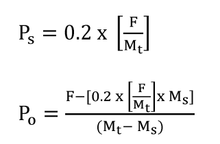
Where:
P s = the portion of the fee under paragraph (c) of this section that is owed by a person who qualifies as a small business concern under §700.43 of this chapter.
P o = the portion of the fee owed by a person other than a small business concern.
F = the total fee required under paragraph (c) of this section.
M t = the total number of persons subject to the fee requirement.
M s = the number of persons subject to the fee requirement who qualify as a small business concern.
(ii) Each person's share of the applicable fees triggered by section 6(b) of the Act specified in paragraph (c) of this section shall be in proportion to the total number of manufacturers and their reported production volume as described in §700.45(b)(v) of the chemical substance, with lower fees for small businesses:
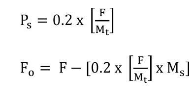
(iii) Remaining manufacturers ( i.e., those that do not qualify as a small business concern) are then ranked in ascending order (from lowest to highest) based on reported production volume as described in §700.45(b)(v). Each remaining manufacturer is assigned a number with 1 for lowest production volume, 2 for second lowest production volume, etc.
| Manufacturer(s) | Assigned No. (N) |
|---|---|
| Manufacturer with lowest production volume | 1 |
| Manufacturer with 2nd lowest production volume | 2 |
| Manufacturer with 3rd lowest production volume | 3 |
| . . . etc. |
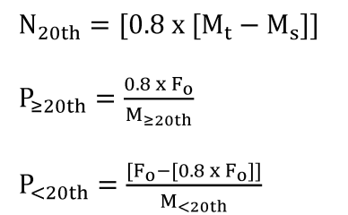
Where:
P s = the portion of the fee under paragraph (c) of this section that is owed by a person who qualifies as a small business concern under §700.43 of this chapter.
P ≥20th = the portion of the fee owed by a person other than a small business concern in the top 20th percentile.
P <20th = the portion of the fee owed by a person other than a small business concern not in the top 20th percentile.
F = the total fee required under paragraph (c) of this section.
M t = the total number of persons subject to the fee requirement.
M s = the number of persons subject to the fee requirement who qualify as a small business concern.
N 20th = The assigned number as illustrated in Table 1 to the manufacturer(s) with a production volume as described in §1.45(b)(v) at which the manufacturers with production volume greater than or equal to are in the top 20th percentile.
M ≥20th = the total number of persons with production volume as described in 700.45(b)(v) greater than or equal to the manufacturer(s) with a production volume as N 20th .
M <20th = the total number of persons with production volume as described in 700.45(b)(v) less than the manufacturer(s) with a production volume as N 20th .
F o = the total fee required under paragraph (c) of this section by all person(s) other than a small business concern.
(iv) In the event there are three or less manufacturers identified for a chemical substance, EPA will distribute the fee evenly among those three or less fee payers, regardless of production volume.
(v) In the event the number assigned to the top 20th percentile is not an integer, EPA will round to the nearest integer to determine the manufacturer(s) with the reported production volume as described in §700.45(b)(v) greater than or equal to the top 20th percentile.
(vi) In the event multiple manufacturers report the same production volume as described in §700.45(b)(v) and are greater than or equal to the top 20th percentile, EPA will include all manufacturers with that same production volume in the fee calculation for the top 20th percentile group.
(5) If multiple persons are subject to fees triggered by section 4 of the Act and some inform EPA of their intent to form a consortium while others choose not to associate with the consortium, EPA will take the following steps to allocate fee amounts:
(i) Count the total number of manufacturers, including the number of manufacturers within any consortia; divide the total fee amount by the total number of manufacturers; and allocate equally on a per capita basis to generate a base fee;
(ii) Provide all small businesses who are either not associated with a consortium, or associated with an all- small business consortium, with an 80% discount from the base fee referenced previously;
(iii) Calculate the total remaining fee and total number of remaining manufacturers by subtracting out the discounted fees and the number of small businesses identified;
(iv) Reallocate the remaining fee across those remaining individuals and groups in equal amounts, counting each manufacturer in a consortium as one person; and
(v) Inform consortia and individuals of their requisite fee amount. Small businesses in a successfully-formed consortium, other than a consortium of all small businesses, will not be afforded the 80% discount by EPA, but consortia managers are strongly encouraged to provide a discount for small business concerns.
* * * * *
(g) * * *
(3) * * *
(i) Test orders and test rules. The applicable fee specified in paragraph (c) of this section shall be paid in full not later than 180 days after the effective date of a test rule or test order under section 4 of the Act.
* * * * *
(iv) Risk evaluations. (A) For EPA-initiated risk evaluations, the applicable fee specified in paragraph (c) of this section shall be paid in two installments, with the first payment of 50% due 180 days after publishing the final scope of a risk evaluation and the second payment for the remainder of the fee due 545 days after publishing the final scope of a risk evaluation under section 6(b)(4)(D) of the Act.
(B) For manufacturer-requested risk evaluations under section 6(b)(4)(C)(ii) of the Act, the applicable fees specified in paragraph (c) of this section shall be paid as follows:
( 1 ) The applicable fee specified in paragraph (c) of this section shall be paid in three installments. The first payment shall be due no later than 180 days after EPA provides the submitting manufacture(s) notice that it has granted the request.
( 2 ) The second payment shall be due no later than 545 days after EPA provides the submitting manufacturer(s) notice that it has granted the request.
( 3 ) The final payment shall be due no later than 30 days after EPA publishes the final risk evaluation.
* * * * *
(5) Small business certification. (i) Each person who remits the fee identified in paragraph (c)(1) of this section for a PMN, consolidated PMN, or SNUN shall insert a check mark for the statement, “The company named in part 1, section A is a small business concern under 40 CFR 700.43 and has remitted a fee of $6,480 in accordance with 40 CFR 700.45(c).” under “CERTIFICATION” on page 2 of the Premanufacture Notice for New Chemical Substances (EPA Form 7710–25).
(ii) Each person who remits the fee identified in paragraph (c)(1) of this section for a LVE, LoREX, TERA, TME, or Tier II exemption request under TSCA section 5 shall insert a check mark for the statement, “The company named in part 1, section A is a small business concern under 40 CFR 700.43 and has remitted a fee of $2,180 in accordance with 40 CFR 700.45(c).” in the exemption application.
(iii) Each person who remits the fee identified in paragraph (c)(1) of this section for an exemption notice under §723.175 of this chapter shall include the words, “The company or companies identified in this notice is/are a small business concern under 40 CFR 700.43 and has/have remitted a fee of $2,180 in accordance with 40 CFR 700.45(c).” in the certification required in §723.175(i)(1)(x) of this chapter.
(iv) Each person who remits the fee identified in paragraph (c)(1) of this section for a MCAN or consolidated MCAN for a microorganism shall insert a check mark for the statement, “The company named in part 1, section A is a small business concern under 40 CFR 700.43 and has remitted a fee of $6,480 in accordance with 40 CFR 700.45(c).” in the certification required in §725.25(b) of this chapter.
(6) Payment certification statement. (i) Each person who remits a fee identified in paragraph (c)(2) of this section for a PMN, consolidated PMN, or SNUN shall insert a check mark for the statement, “The company named in part 1, section A has remitted the fee of $37,000 specified in 40 CFR 700.45(c).” under “CERTIFICATION” on page 2 of the Premanufacture Notice for New Chemical Substances (EPA Form 7710–25).
(ii) Each person who remits a fee identified in paragraph (c)(2) of this section for a LVE, LoREX, TERA, TME, or Tier II exemption request under TSCA section 5 shall insert a check mark for the statement, “The company named in part 1, section A has remitted the fee of $10,870 specified in 40 CFR 700.45(c).” in the exemption application.
(iii) Each person who remits the fee identified in paragraph (c)(2) of this section for an exemption notice under §723.175 of this chapter shall include the words, “The company or companies identified in this notice has/have remitted a fee of $10,870 in accordance with 40 CFR 700.45(c).” in the certification required in §723.175(i)(1)(x) of this chapter.
(iv) Each person who remits the fee identified in paragraph (c)(2) of this section for a MCAN for a microorganism shall insert a check mark for the statement, “The company named in part 1, section A has remitted the fee of $37,000 in accordance with 40 CFR 700.45(c).” in the certification required in §725.25(b) of this chapter.