['Air Programs']
['Hazardous Air Pollutants']
02/27/2022

Copyright 2026 J. J. Keller & Associate, Inc. For re-use options please contact copyright@jjkeller.com or call 800-558-5011.
...
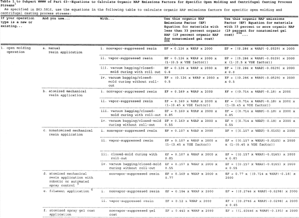
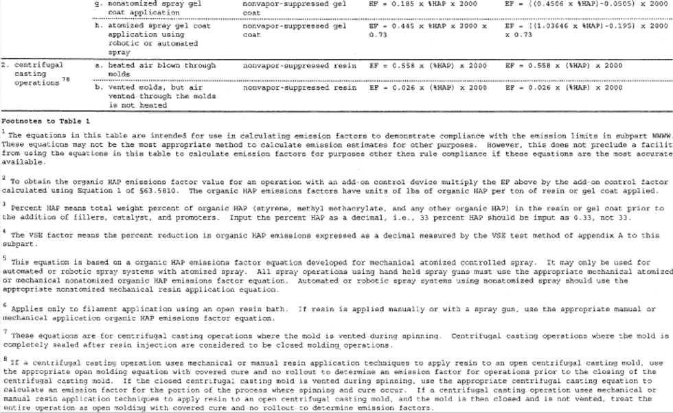
Table 1 to Subpart WWWW of Part 63 - Equations To Calculate Organic HAP Emissions Factors for Specific Open Molding and Centrifugal Casting Process Streams
[70 FR 50129, Aug. 26, 2005]
Table 2 to Subpart WWWW of Part 63 - Compliance Dates for New and Existing Reinforced Plastic Composites Facilities
As required in §§63.5800 and 63.5840 you must demonstrate compliance with the standards by the dates in the following table:
| If your facility is . . . | And . . . | Then you must comply by this date . . . |
|---|---|---|
| 1. An existing source | a. Is a major source on or before the publication date of this subpart | April 21, 2006. |
| 2. An existing source that is an area source | Becomes a major source after the publication date of this subpart | 3 years after becoming a major source or April 21, 2006, whichever is later. |
| 3. An existing source, and emits less than 100 tpy of organic HAP from the combination of all centrifugal casting and continuous lamination/casting operations at the time of initial compliance with this subpart | Subsequently increases its actual organic HAP emissions to 100 tpy or more from these operations, which requires that the facility must now comply with the standards in §63.5805(b) | 3 years of the date your semi-annual compliance report indicates your facility meets or exceeds the 100 tpy threshold. |
| 4. A new source | Is a major source at startup | Upon startup or April 21, 2003, whichever is later. |
| 5. A new source | Is an area source at startup and becomes a major source | Immediately upon becoming a major source. |
| 6. A new source, and emits less than 100 tpy of organic HAP from the combination of all open molding, centrifugal casting, continuous lamination/casting, pultrusion, SMC and BMC manufacturing, and mixing operations at the time of initial compliance with this subpart | Subsequently increases its actual organic HAP emissions to 100 tpy or more from the combination of these operations, which requires that the facility must now meet the standards in §63.5805(d) | 3 years from the date that your semi-annual compliance report indicates your facility meets or exceeds the 100 tpy threshold. |
[85 FR 73910, Nov. 19, 2020]
Table 3 to Subpart WWWW of Part 63 - Organic HAP Emissions Limits for Existing Open Molding Sources, New Open Molding Sources Emitting Less Than 100 TPY of HAP, and New and Existing Centrifugal Casting and Continuous Lamination/Casting Sources that Emit Less Than 100 TPY of HAP
As specified in §63.5805, you must meet the following organic HAP emissions limits that apply to you:
| If your operation type is . . . | And you use . . . | 1 Your organic HAP emissions limit is . . . |
|---|---|---|
| 1 Organic HAP emissions limits for open molding and centrifugal casting are expressed as lb/ton. You must be at or below these values based on a 12-month rolling average. 2 This emission limit applies regardless of whether the shrinkage controlled resin is used as a production resin or a tooling resin. 3 If you only apply gel coat with manual application, for compliance purposes treat the gel coat as if it were applied using atomized spray guns to determine both emission limits and emission factors. If you use multiple application methods and any portion of a specific gel coat is applied using nonatomized spray, you may use the nonatomized spray gel coat equation to calculate an emission factor for the manually applied portion of that gel coat. Otherwise, use the atomized spray gel coat application equation to calculate emission factors. 4 For compliance purposes, calculate your emission factor using only the appropriate centrifugal casting equation in item 2 of Table 1 to this subpart, or a site specific emission factor for after the mold is closed as discussed in §63.5796. 5 Calculate your emission factor using the appropriate open molding covered cure emission factor in item 1 of Table 1 to this subpart, or a site specific emission factor as discussed in §63.5796. 6 Pultrusion machines that produce parts that meet the following criteria: 1,000 or more reinforcements or the glass equivalent of 1,000 ends of 113 yield roving or more; and have a cross sectional area of 60 square inches or more are not subject to this requirement. Their requirement is the work practice of air flow management which is described in Table 4 to this subpart. | ||
| 1. open molding - corrosion-resistant and/or high strength (CR/HS) | a. mechanical resin application b. filament application c. manual resin application | 113 lb/ton. 171 lb/ton. 123 lb/ton. |
| 2. open molding - non-CR/HS | a. mechanical resin application b. filament application c. manual resin application | 88 lb/ton. 188 lb/ton. 87 lb/ton. |
| 3. open molding - tooling | a. mechanical resin application b. manual resin application | 254 lb/ton. 157 lb/ton. |
| 4. open molding - low-flame spread/low-smoke products | a. mechanical resin application b. filament application c. manual resin application | 497 lb/ton. 270 lb/ton. 238 lb/ton. |
| 5. open molding - shrinkage controlled resins 2 | a. mechanical resin application b. filament application c. manual resin application | 354 lb/ton. 215 lb/ton. 180 lb/ton. |
| 6. open molding - gel coat 3 | a. tooling gel coating b. white/off white pigmented gel coating c. all other pigmented gel coating d. CR/HS or high performance gel coat e. fire retardant gel coat f. clear production gel coat | 440 lb/ton. 267 lb/ton. 377 lb/ton. 605 lb/ton. 854 lb/ton. 522 lb/ton. |
| 7. centrifugal casting - CR/HS | a. resin application with the mold closed, and the mold is vented during spinning and cure b. resin application with the mold closed, and the mold is not vented during spinning and cure c. resin application with the mold open, and the mold is vented during spinning and cure d. resin application with the mold open, and the mold is not vented during spinning and cure | 25 lb/ton. 4 NA - this is considered to be a closed molding operation. 25 lb/ton. 4 Use the appropriate open molding emission limit. 5 |
| 8. centrifugal casting - non-CR/HS | a. resin application with the mold closed, and the mold is vented during spinning and cure b. resin application with the mold closed, and mold is not vented during the spinning and cure c. resin application with the mold open, and the mold is vented during spinning and cure d. resin application with the mold open, and the mold is not vented during spinning and cure | 20 lb/ton. 4 NA - this is considered to be a closed molding operation. 20 lb/ton. 4 Use the appropriate open molding emission limit. 5 |
| 9. pultrusion 6 | N/A | reduce total organic HAP emissions by at least 60 weight percent. |
| 10. continuous lamination/casting | N/A | reduce total organic HAP emissions by at least 58.5 weight percent or not exceed an organic HAP emissions limit of 15.7 lbs of organic HAP per ton of neat resin plus and neat gel coat plus. |
[70 FR 50131, Aug. 25, 2005]
Table 4 to Subpart WWWW of Part 63 - Work Practice Standards
As specified in §63.5805, you must meet the work practice standards in the following table that apply to you:
| For . . . | You must . . . |
|---|---|
| 1?Containers of 5 gallons or less may be open when active mixing is taking place, or during periods when they are in process (i.e., they are actively being used to apply resin). For polymer casting mixing operations, containers with a surface area of 500 square inches or less may be open while active mixing is taking place. | |
| 1. A new or existing closed molding operation using compression/injection molding | Uncover, unwrap or expose only one charge per mold cycle per compression/injection molding machine. For machines with multiple molds, one charge means sufficient material to fill all molds for one cycle. For machines with robotic loaders, no more than one charge may be exposed prior to the loader. For machines fed by hoppers, sufficient material may be uncovered to fill the hopper. Hoppers must be closed when not adding materials. Materials may be uncovered to feed to slitting machines. Materials must be recovered after slitting. |
| 2. A new or existing cleaning operation | Not use cleaning solvents that contain HAP, except that styrene may be used as a cleaner in closed systems, and organic HAP containing cleaners may be used to clean cured resin from application equipment. Application equipment includes any equipment that directly contacts resin. |
| 3. A new or existing materials HAP-containing materials storage operation | Keep containers that store HAP-containing materials closed or covered except during the addition or removal of materials. Bulk HAP-containing materials storage tanks may be vented as necessary for safety. |
| 4. An existing or new SMC manufacturing operation | Close or cover the resin delivery system to the doctor box on each SMC manufacturing machine. The doctor box itself may be open. |
| 5. An existing or new SMC manufacturing operation | Use a nylon containing film to enclose SMC. |
| 6. All mixing or BMC manufacturing operations1 | Use mixer covers with no visible gaps present in the mixer covers, except that gaps of up to 1 inch are permissible around mixer shafts and any required instrumentation. Mixers where the emissions are fully captured and routed to a 95 percent efficient control device are exempt from this requirement. |
| 7. All mixing or BMC manufacturing operations1 | Close any mixer vents when actual mixing is occurring, except that venting is allowed during addition of materials, or as necessary prior to adding materials or opening the cover for safety. Vents routed to a 95 percent efficient control device are exempt from this requirement. |
| 8. All mixing or BMC manufacturing operations1 | Keep the mixer covers closed while actual mixing is occurring except when adding materials or changing covers to the mixing vessels. |
| 9. A new or existing pultrusion operation manufacturing parts that meet the following criteria: 1,000 or more reinforcements or the glass equivalent of 1,000 ends of 113 yield roving or more; and have a cross sectional area of 60 square inches or more that is not subject to the 95-percent organic HAP emission reduction requirement | i. Not allow vents from the building ventilation system, or local or portable fans to blow directly on or across the wet-out area(s), ii. Not permit point suction of ambient air in the wet-out area(s) unless that air is directed to a control device, iii. Use devices such as deflectors, baffles, and curtains when practical to reduce air flow velocity across the wet-out area(s), iv. Direct any compressed air exhausts away from resin and wet-out area(s), |
| ? | v. Convey resin collected from drip-off pans or other devices to reservoirs, tanks, or sumps via covered troughs, pipes, or other covered conveyance that shields the resin from the ambient air, vi. Cover all reservoirs, tanks, sumps, or HAP-containing materials storage vessels except when they are being charged or filled, and vii. Cover or shield from ambient air resin delivery systems to the wet-out area(s) from reservoirs, tanks, or sumps where practical. |
[70 FR 50133, Aug. 25, 2005; 85 FR 15977, March 20, 2020]
Table 5 to Subpart WWWW of Part 63 - Alternative Organic HAP Emissions Limits for Open Molding, Centrifugal Casting, and SMC Manufacturing Operations Where the Standards Are Based on a 95 Percent Reduction Requirement
As specified in §63.5805, as an alternative to the 95 percent organic HAP emissions reductions requirement, you may meet the appropriate organic HAP emissions limits in the following table:
| If your operation type is . . . | And you use . . . | LYour organic HAP emissions limit is a 1. . . |
|---|---|---|
| 1 Organic HAP emissions limits for open molding and centrifugal casting expressed as lb/ton are calculated using the equations shown in Table 1 to this subpart. You must be at or below these values based on a 12-month rolling average. 2 These limits are for spray application of gel coat. Manual gel coat application must be included as part of spray gel coat application for compliance purposes using the same organic HAP emissions factor equation and organic HAP emissions limit. If you only apply gel coat with manual application, treat the manually applied gel coat as if it were applied with atomized spray for compliance determinations. 3 Centrifugal casting operations where the mold is not vented during spinning and cure are considered to be closed molding and are not subject to any emissions limit. Centrifugal casting operations where the mold is not vented during spinning and cure, and the resin is applied to the open centrifugal casting mold using mechanical or manual open molding resin application techniques are considered to be open molding operations and the appropriate open molding emission limits apply. 4 Centrifugal casting operations where the mold is vented during spinning and the resin is applied to the open centrifugal casting mold using mechanical or manual open molding resin application techniques, use the appropriate centrifugal casting emission limit to determine compliance. Calculate your emission factor using the appropriate centrifugal casting emission factor in Table 1 to this subpart, or a site specific emission factor as discussed in §63.5796. | ||
| 1. Open molding - corrosion-resistant and/or high strength (CR/HS) | a. Mechanical resin application | 6 lb/ton. |
| b. Filament application | 9 lb/ton. | |
| c. Manual resin application | 7 lb/ton. | |
| 2. Open molding - non-CR/HS | a. mechanical resin application | 13 lb/ton. |
| b. Filament application | 10 lb/ton. | |
| c. Manual resin application | 5 lb/ton. | |
| 3. Open molding - tooling | a. Mechanical resin application | 13 lb/ton. |
| b. Manual resin application | 8 lb/ton. | |
| 4. Open molding - low flame spread/low smoke products | a. Mechanical resin application | 25 lb/ton. |
| b. Filament application | 14 lb/ton. | |
| c. Manual resin application | 12 lb/ton. | |
| 5. Open molding - shrinkage controlled resins | a. Mechanical resin application | 18 lb/ton. |
| b. Filament application | 11 lb/ton. | |
| c. Manual resin application | 9 lb/ton. | |
| 6. Open molding - gel coat 2 | a. Tooling gel coating | 22 lb/ton. |
| b. White/off white pigmented gel coating | 22 lb/ton. | |
| c. All other pigmented gel coating | 19 lb/ton. | |
| d. CR/HS or high performance gel coat | 31 lb/ton. | |
| e. Fire retardant gel coat | 43 lb/ton. | |
| f. Clear production gel coat | 27 lb/ton. | |
| 7. Centrifugal casting - CR/HS 3 4 | A vent system that moves heated air through the mold | 27 lb/ton. |
| 8. Centrifugal casting - non-CR/HS 3 4 | A vent system that moves heated air through the mold | 21 lb/ton. |
| 7. Centrifugal casting - CR/HS 3 4 | A vent system that moves ambient air through the mold | 2 lb/ton. |
| 8. Centrifugal casting - non-CR/HS 3 4 | A vent system that moves ambient air through the mold | 1 lb/ton. |
| 9. SMC Manufacturing | N/A | 2.4 lb/ton. |
[68 FR 19402, Apr. 21, 2003, as amended at 70 FR 50133, Aug. 25, 2005]
Table 6 to Subpart WWWW of Part 63 - Basic Requirements for Performance Tests, Performance Evaluations, and Design Evaluations for New and Existing Sources Using Add-On Control Devices
As required in §63.5850 you must conduct performance tests, performance evaluations, and design evaluation according to the requirements in the following table:
| For . . . | You must . . . | Using . . . | According to the following requirements . . . |
|---|---|---|---|
| 1. Each enclosure used to collect and route organic HAP emissions to an add-on control device that is a PTE | Meet the requirements for a PTE | EPA method 204 of appendix M of 40 CFR part 51 | Enclosures that meet the requirements of EPA Method 204 of appendix M of 40 CFR part 51 for a PTE are assumed to have a capture efficiency of 100%. Note that the criteria that all access doors and windows that are not treated as natural draft openings shall be closed during routine operation of the process is not intended to require that these doors and windows be closed at all times. It means that doors and windows must be closed any time that you are not actually moving parts or equipment through them. Also, any styrene retained in hollow parts and liberated outside the PTE is not considered to be a violation of the EPA Method 204 criteria. |
| 2. Each enclosure used to collect and route organic HAP emissions to an add-on control device that is not a PTE | a. Determine the capture efficiency of each enclosure used to capture organic HAP emissions sent to an add-on control device | i. EPA methods 204B through E of appendix M of 40 CFR part 51, or | (1) Enclosures that do not meet the requirements for a PTE must determine the capture efficiency by constructing a temporary total enclosure according to the requirements of EPA Method 204 of appendix M of 40 CFR part 51 and measuring the mass flow rates of the organic HAP in the exhaust streams going to the atmosphere and to the control device. Test runs for EPA Methods 204B through E of appendix M of 40 CFR part 51 must be at least 3 hours. |
| ii. An alternative test method that meets the requirements in 40 CFR part 51, appendix M | (1) The alternative test method must the data quality objectives and lower confidence limit approaches for alternative capture efficiency protocols requirements contained in 40 CFR part 63 subpart KK, appendix A. | ||
| 3. Each control device used to comply with a percent reduction requirement, or an organic HAP emissions limit | Determine the control efficiency of each control device used to control organic HAP emissions | The test methods specified in §63.5850 to this subpart | Testing and evaluation requirements are contained in 40 CFR part 63, subpart SS, and §63.5850 to this subpart. |
| 4. Determining organic HAP emission factors for any operation | Determine the mass organic HAP emissions rate | The test methods specified in §63.5850 to this subpart | Testing and evaluation requirements are contained in 40 CFR part 63, subpart SS, and §63.5850 to this subpart. |
Table 7 to Subpart WWWW of Part 63 - Options Allowing Use of the Same Resin Across Different Operations That Use the Same Resin Type
As specified in §63.5810(d), when electing to use the same resin(s) for multiple resin application methods, you may use any resin(s) with an organic HAP content less than or equal to the values shown in the following table, or any combination of resins whose weighted average organic HAP content based on a 12-month rolling average is less than or equal to the values shown the following table:
| If your facility has the following resin type and application method . . . | The highest resin weight is* * * percent organic HAP content, or weighted average weight percent organic HAP content, you can use for . . . | is . . . |
|---|---|---|
| 1 If the centrifugal casting operation blows heated air through the molds, then 95 percent capture and control must be used if the facility wishes to use this compliance option. 2 If the centrifugal casting molds are not vented, the facility may treat the centrifugal casting operations as if they were vented if they wish to use this compliance option. 3 Nonatomized mechanical application must be used. | ||
| 1. CR/HS resins, centrifugal casting 1 2 | a. CR/HS mechanical | 3 48.0 |
| b. CR/HS filament application | 48.0 | |
| c. CR/HS manual | 48.0 | |
| 2. CR/HS resins, nonatomized mechanical | a. CR/HS filament application | 46.4 |
| b. CR/HS manual | 46.4 | |
| 3. CR/HS resins, filament application | CR/HS manual | 42.0 |
| 4. non-CR/HS resins, filament application | a. non-CR/HS mechanical | 3 45.0 |
| b. non-CR/HS manual | 45.0 | |
| c. non-CR/HS centrifugal casting 1 2 | 45.0 | |
| 5. non-CR/HS resins, nonatomized mechanical | a. non-CR/HS manual | 38.5 |
| b. non-CR/HS centrifugal casting 1 2 | 38.5 | |
| 6. non-CR/HS resins, centrifugal casting 1 2 | non-CR/HS manual | 37.5 |
| 7. tooling resins, nonatomized mechanical | tooling manual | 91.4 |
| 8. tooling resins, manual | tooling atomized mechanical | 45.9 |
[70 FR 50133, Aug. 25, 2005]
Table 8 to Subpart WWWW of Part 63 - Initial Compliance With Organic HAP Emissions Limits
As specified in §63.5860(a), you must demonstrate initial compliance with organic HAP emissions limits as specified in the following table:
| For . . . | That must meet the following organic HAP emissions limit . . . | You have demonstrated initial compliance if . . . |
|---|---|---|
| 1. open molding and centrifugal casting operations | a. an organic HAP emissions limit shown in Tables 3 or 5 to this subpart, or an organic HAP content limit shown in Table 7 to this subpart | i. you have met the appropriate organic HAP emissions limits for these operations as calculated using the procedures in §63.5810 on a 12-month rolling average 1 year after the appropriate compliance date, and/or ii. you demonstrate that any individual resins or gel coats not included in (i) above, as applied, meet their applicable emission limits, or iii. you demonstrate using the appropriate values in Table 7 to this subpart that the weighted average of all resins and gel coats for each resin type and application method meet the appropriate organic HAP contents. |
| 2. open molding centrifugal casting, continuous lamination/casting, SMC and BMC manufacturing, and mixing operations | a. reduce total organic HAP emissions by at least 95 percent by weight | total organic HAP emissions, based on the results of the capture efficiency and destruction efficiency testing specified in Table 6 to this subpart, are reduced by at least 95 percent by weight. |
| 3. continuous lamination/casting operations | a. reduce total organic HAP emissions, by at least 58.5 weight percent, or | total organic HAP emissions, based on the results of the capture efficiency and destruction efficiency in Table 6 to this subpart and the calculation procedures specified in §§63.5865 through 63.5890, are reduced by at least 58.5 percent by weight. |
| b. not exceed an organic HAP emissions limit of 15.7 lbs of organic HAP per ton of neat resin plus and neat gel coat plus | total organic HAP emissions, based on the results of the capture efficiency and destruction efficiency testing specified in Table 6 to this subpart and the calculation procedures specified in §§63.5865 through 63.5890, do not exceed 15.7 lbs of organic HAP per ton of neat resin plus and neat gel coat plus. | |
| 4. continuous lamination/casting operations | a. reduce total organic HAP emissions by at least 95 weight percent or | total organic HAP emissions, based on the results of the capture efficiency and destruction efficiency testing specified in Table 6 to this subpart and the calculation procedures specified in §§63.5865 through 63.5890, are reduced by at least 95 percent by weight |
| b. not exceed an organic HAP emissions limit of 1.47 lbs of organic HAP per ton of neat resin plus and neat gel coat plus | total organic HAP emissions, based on the results of the capture efficiency and destruction efficiency testing specified in Table 6 and the calculation procedures specified in §§63.5865 through 63.5890, do not exceed 1.47 lbs of organic HAP of per ton of neat resin plus and neat gel coat plus. | |
| 5. pultrusion operations | a. reduce total organic HAP emissions by at least 60 percent by weight | i. total organic HAP emissions, based on the results of the capture efficiency and add-on control device destruction efficiency testing specified in Table 6 to this subpart, are reduced by at least 60 percent by weight, and/or ii. as part of the notification of initial compliance status, the owner/operator submits a certified statement that all pultrusion lines not controlled with an add-on control device, but for which an emission reduction is being claimed, are using direct die injection, and/or wet-area enclosures that meet the criteria of §63.5830. |
| 6. pultrusion operations | a. reduce total organic HAP emissions by at least 95 percent by weight | i. total organic HAP emissions, based on the results of the capture efficiency and add-on control device destruction efficiency testing specified in Table 6 to this subpart, are reduced by at least 95 percent by weight. |
[70 FR 50134, Aug. 25, 2005]
Table 9 to Subpart WWWW of Part 63 - Initial Compliance With Work Practice Standards
As specified in §63.5860(a), you must demonstrate initial compliance with work practice standards as specified in the following table:
| For . . . | That must meet the following standards . . . | You have demonstrated initial compliance if . . . |
|---|---|---|
| 1. a new or existing closed molding operation using compression/injection molding | uncover, unwrap or expose only one charge per mold cycle per compression/injection molding machine. For machines with multiple molds, one charge means sufficient material to fill all molds for one cycle. For machines with robotic loaders, no more than one charge may be exposed prior to the loader. For machines fed by hoppers, sufficient material may be uncovered to fill the hopper. Hoppers must be closed when not adding materials. Materials may be uncovered to feed to slitting machines. Materials must be recovered after slitting | the owner or operator submits a certified statement in the notice of compliance status that only one charge is uncovered, unwrapped, or exposed per mold cycle per compression/injection molding machine, or prior to the loader, hoppers are closed except when adding materials, and materials are recovered after slitting. |
| 2. a new or existing cleaning operation | not use cleaning solvents that contain HAP, except that styrene may be used in closed systems, and organic HAP containing materials may be used to clean cured resin from application equipment. Application equipment includes any equipment that directly contacts resin between storage and applying resin to the mold or reinforcement | the owner or operator submits a certified statement in the notice of compliance status that all cleaning materials, except styrene contained in closed systems, or materials used to clean cured resin from application equipment, contain no HAP. |
| 3. a new or existing materials HAP-containing materials storage operation | keep containers that store HAP-containing materials closed or covered except during the addition or removal of materials. Bulk HAP-containing materials storage tanks may be vented as necessary for safety | the owner or operator submits a certified statement in the notice of compliance status that all HAP-containing storage containers are kept closed or covered except when adding or removing materials, and that any bulk storage tanks are vented only as necessary for safety. |
| 4. an existing or new SMC manufacturing operation | close or cover the resin delivery system to the doctor box on each SMC manufacturing machine. The doctor box itself may be open | the owner or operator submits a certified statement in the notice of compliance status that the resin delivery system is closed or covered. |
| 5. an existing or new SMC manufacturing operation | use a nylon containing film to enclose SMC | the owner or operator submits a certified statement in the notice of compliance status that a nylon-containing film is used to enclose SMC. |
| 6. an existing or new mixing or BMC manufacturing operation | use mixer covers with no visible gaps present in the mixer covers, except that gaps of up to 1 inch are permissible around mixer shafts and any required instrumentation | the owner or operator submits a certified statement in the notice of compliance status that mixer covers are closed during mixing except when adding materials to the mixers, and that gaps around mixer shafts and required instrumentation are less than 1 inch. |
| 7. an existing mixing or BMC manufacturing operation | not actively vent mixers to the atmosphere while the mixing agitator is turning, except that venting is allowed during addition of materials, or as necessary prior to adding materials for safety | the owner or operator submits a certified statement in the notice of compliance status that mixers are not actively vented to the atmosphere when the agitator is turning except when adding materials or as necessary for safety. |
| 8. a new or existing mixing or BMC manufacturing operation | keep the mixer covers closed during mixing except when adding materials to the mixing vessels | the owner or operator submits a certified statement in the notice of compliance status that mixers closed except when adding materials to the mixing vessels. |
| 9. a new or existing pultrusion operation manufacturing parts that meet the following criteria: 1,000 or more reinforcements or the glass equivalent of 1,000 ends of 113 yield roving or more; and have a cross sectional area of 60 square inches or more that is not subject to the 95 percent organic HAP emission reduction requirement | i. Not allow vents from the building ventilation system, or local or portable fans to blow directly on or across the wet-out area(s), ii. not permit point suction of ambient air in the wet-out area(s) unless that air is directed to a control device, iii. use devices such as deflectors, baffles, and curtains when practical to reduce air flow velocity across the wet-out area(s), iv. direct any compressed air exhausts away from resin and wet-out area(s), v. convey resin collected from drip-off pans or other devices to reservoirs, tanks, or sumps via covered troughs, pipes, or other covered conveyance that shields the resin from the ambient air, vi. clover all reservoirs, tanks, sumps, or HAP-containing materials storage vessels except when they are being charged or filled, and vii. cover or shield from ambient air resin delivery systems to the wet-out area(s) from reservoirs, tanks, or sumps where practical. | the owner or operator submits a certified statement in the notice of compliance status that they have complied with all the requirements listed in 9.i through 9.vii. |
[70 FR 50135, Aug. 25, 2005]
Table 10 to Subpart WWWW of Part 63 - Data Requirements for New and Existing Continuous Lamination Lines and Continuous Casting Lines Complying With a Percent Reduction Limit on a Per Line Basis
As required in §63.5865(a), in order to comply with a percent reduction limit for continuous lamination lines and continuous casting lines you must determine the data in the following table:
| For each line where the wet-out area . . . | And the oven . . . | You must determine . . . |
|---|---|---|
| 1. Has an enclosure that is not a permanent total enclosure (PTE) and the captured organic HAP emissions are controlled by an add-on control device | a. Is uncontrolled | i. Annual uncontrolled wet-out area organic HAP emissions, ii. Annual controlled wet-out area organic HAP emissions, iii. Annual uncontrolled oven organic HAP emissions, iv. The capture efficiency of the wet-out area enclosure, |
| v. The destruction efficiency of the add-on control device, and vi. The amount of neat resin plus and neat gel coat plus applied. | ||
| 2. Has an enclosure that is a PTE and the captured organic HAP emissions are controlled by an add-on control device | a. Is uncontrolled | i. Annual uncontrolled wet-out area organic HAP emissions, ii. Annual controlled wet-out area organic HAP emissions, iii. Annual uncontrolled oven organic HAP emissions, iv. That the wet-out area enclosure meets the requirements of EPA Method 204 of appendix M to 40 CFR part 51 for a PTE, v. The destruction efficiency of the add-on control device, and vi. The amount of neat resin plus and neat gel coat plus applied. |
| 3. Is uncontrolled | a. Is controlled by an add-on control device | i. Annual uncontrolled wet-out area organic HAP emissions, ii. Annual uncontrolled oven organic HAP emissions, iii. Annual controlled oven organic HAP emissions, iv. The capture efficiency of the oven, v. the destruction efficiency of the add-on control device, and vi. the amount of neat resin plus and neat gel coat plus applied. |
| 4. Has an enclosure that is not a PTE and the captured organic HAP emissions are controlled by an add-on control device | a. Is controlled by an add-on control device | i. Annual uncontrolled wet-out area organic HAP emissions, ii. Annual controlled wet-out area organic HAP emissions, iii. Annual uncontrolled oven organic HAP emissions, iv. Annual controlled oven organic HAP emissions; v. The capture efficiency of the wet-out area enclosure, vi. Inlet organic HAP emissions to the add-on control device, vii. Outlet organic HAP emissions from the add-on control device, and viii. The amount of neat resin plus and neat gel coat plus applied. |
| 5. Has an enclosure that is a PTE and the captured organic HAP emissions are controlled by an add-on control device | a. Is controlled by an add-on control device | i. That the wet-out area enclosure meets the requirements of EPA Method 204 of appendix M to 40 CFR part 51 for a PTE, ii. The capture efficiency of the oven, and |
| iii. The destruction efficiency of the add-on control device. |
Table 11 to Subpart WWWW of Part 63 - Data Requirements for New and Existing Continuous Lamination and Continuous Casting Lines Complying With a Percent Reduction Limit or a Lbs/Ton Limit on an Averaging Basis
As required in §63.5865, in order to comply with a percent reduction limit or a lbs/ton limit on an averaging basis for continuous lamination lines and continuous casting lines you must determine the data in the following table:
| For each . . . | That . . . | You must determine . . . |
|---|---|---|
| 1. Wet-out area | Is uncontrolled | Annual uncontrolled wet-out area organic HAP emissions. |
| 2. Wet-out area | a. Has an enclosure that is not a PTE | i. The capture efficiency of the enclosure, and ii. Annual organic HAP emissions that escape the enclosure. |
| 3. Wet-out area | Has an enclosure that is a PTE | That the enclosure meets the requirements of EPA Method 204 of appendix M to 40 CFR part 51 for a PTE. |
| 4. Oven | Is uncontrolled | Annual uncontrolled oven organic HAP emissions. |
| 5. Line | a. Is controlled or uncontrolled | i. The amount of neat resin plus applied, and ii. The amount of neat gel coat plus applied. |
| 6. Add-on control device | i. Total annual inlet organic HAP emissions, and total annual outlet organic HAP emissions. |
Table 12 to Subpart WWWW of Part 63 - Data Requirements for New and Existing Continuous Lamination Lines and Continuous Casting Lines Complying With a Lbs/Ton Organic HAP Emissions Limit on a Per Line Basis
As required in §63.5865(b), in order to comply with a lbs/ton organic HAP emissions limit for continuous lamination lines and continuous casting lines you must determine the data in the following table:
| For each line where the wet- out area . . . | And the oven . . . | You must determine . . . |
|---|---|---|
| 1. Is uncontrolled | a. Is uncontrolled | i. Annual uncontrolled wet-out area organic HAP emissions, ii. Annual uncontrolled oven organic HAP emissions, and iii. Annual neat resin plus and neat gel coat plus applied. |
| 2. Has an enclosure that is not a PTE and the captured organic HAP emissions are controlled by an add-on control device | a. Is uncontrolled | i. Annual uncontrolled wet-out area organic HAP emissions, ii. Annual controlled wet-out area organic HAP emissions, iii. Annual uncontrolled oven organic HAP emissions, |
| iv. The capture efficiency of the wet-out area enclosure, v. The destruction efficiency of the add-on control device, and vi. The amount of neat resin plus and neat gel coat plus applied. | ||
| 3. Has an enclosure that is a PTE, and the captured organic HAP emissions are controlled by an add-on control device | a. Is uncontrolled | i. Annual uncontrolled wet-out area organic HAP emissions, ii. Annual controlled wet-out area organic HAP emissions, iii. Annual uncontrolled oven organic HAP emissions, |
| iv. That the wet-out area enclosure meets the requirements of EPA Method 204 of appendix M to 40 CFR part 51 for a PTE, v. The destruction efficiency of the add-on control device, and vi. The amount of neat resin plus and neat gel coat plus applied. | ||
| 4. Is uncontrolled | a. Is controlled by an add-on control device | i. Annual uncontrolled wet-out area organic HAP emissions, ii. Annual uncontrolled oven organic HAP emissions, iii. Annual controlled oven organic HAP emissions, |
| iv. The capture efficiency of the oven, v. The destruction efficiency of the add-on control device, and vi. The amount of neat resin plus and neat gel coat plus applied. | ||
| 5. Has an enclosure that is not a PTE and the captured organic HAP emissions are controlled by an add-on control device | a. Is controlled by an add-on control device | i. Annual uncontrolled wet-out area organic HAP emissions, ii. Annual controlled wet-out area organic HAP emissions, iii. Annual uncontrolled oven organic HAP emissions, |
| iv. Annual controlled oven organic HAP emissions, v. The capture efficiency of the wet-out area enclosure, vi. The capture efficiency of the oven, | ||
| vii. The destruction efficiency of the add-on control device, and viii. The amount of neat resin plus and neat gel coat plus applied. | ||
| 6. Has an enclosure that is a PTE, and the captured organic HAP emissions are controlled by add-on control device | a. Is controlled by an add-on control device | i. That the wet-out area enclosure meets the requirements of EPA Method 204 of appendix M to 40 CFR part 51 for a PTE, ii. The capture efficiency of the oven, iii. Inlet organic HAP emissions to the an add-on control device, and |
| iv. Outlet organic HAP emissions from the add-on control device. |
Table 13 to Subpart WWWW of Part 63 - Applicability and Timing of Notifications
As required in §63.5905(a), you must determine the applicable notifications and submit them by the dates shown in the following table:
| If your facility . . . | You must submit . . . | By this date . . . |
|---|---|---|
| 1. Is an existing source subject to this subpart | An Initial Notification containing the information specified in §63.9(b)(2) | No later than the dates specified in §63.9(b)(2). |
| 2. Is a new source subject to this subpart | The notifications specified in §63.9(b)(4) and (5) | No later than the dates specified §63.9(b)(4) and (5). |
| 3. Qualifies for a compliance extension as specified in §63.9(c) | A request for a compliance extension as specified in §63.9(c) | No later than the dates specified in §63.6(i). |
| 4. Is complying with organic HAP emissions limit averaging provisions | A Notification of Compliance Status as specified in §63.9(h) | No later than 1 year plus 30 days after your facility's compliance date. |
| 5. Is complying with organic HAP content limits, application equipment requirements, or organic HAP emissions limit other than organic HAP emissions limit averaging | A Notification of Compliance Status as specified in §63.9(h) | No later than 30 calendar days after your facility's compliance date. |
| 6. Is complying by using an add-on control device | a. A notification of intent to conduct a performance test as specified in §63.9(e) | No later than the date specified in §63.9(e). |
| b. A notification of the date for the CMS performance evaluation as specified in §63.9(g) | The date of submission of notification of intent to conduct a performance test. | |
| c. A Notification of Compliance Status as specified in §63.9(h) | No later than 60 calendar days after the completion of the add-on control device performance test and CMS performance evaluation. |
Table 14 to Subpart WWWW of Part 63 - Requirements for Reports
As required in §63.5910(a), (b), (g), and (h), you must submit reports on the schedule shown in the following table:
| You must submit a(n) | The report must contain . . . | You must submit the report . . . |
|---|---|---|
| 1. Compliance report | a. A statement that there were no deviations during that reporting period if there were no deviations from any emission limitations (emission limit, operating limit, opacity limit, and visible emission limit) that apply to you and there were no deviations from the requirements for work practice standards in Table 4 to this subpart that apply to you. If there were no periods during which the CMS, including CEMS, and operating parameter monitoring systems, was out of control as specified in §63.8(c)(7), the report must also contain a statement that there were no periods during which the CMS was out of control during the reporting period | Semiannually according to the requirements in §63.5910(b). |
| ? | b. The information in §63.5910(d) if you have a deviation from any emission limitation (emission limit, operating limit, or work practice standard) during the reporting period. If there were periods during which the CMS, including CEMS, and operating parameter monitoring systems, was out of control, as specified in §63.8(c)(7), the report must contain the information in §63.5910(e) | Semiannually according to the requirements in §63.5910(b). |
[85 FR 15978, March 20, 2020]
Table 15 to Subpart WWWW of Part 63 - Applicability of General Provisions (Subpart A) to Subpart WWWW of Part 63
As specified in §63.5925, the parts of the General Provisions which apply to you are shown in the following table:
| The general provisions reference . . . | That addresses . . . | And applies to subpart WWWW of part 63 . . . | Subject to the following additional information . . . |
|---|---|---|---|
| §63.1(a)(1) | General applicability of the general provisions | Yes | Additional terms defined in subpart WWWW of part 63, when overlap between subparts A and WWWW of this part, subpart WWWW of part 63 takes precedence. |
| §63.1(a)(2) through (4) | General applicability of the general provisions | Yes | |
| §63.1(a)(5) | Reserved | No | |
| §63.1(a)(6) | General applicability of the general provisions | Yes | |
| §63.1(a)(7) through (9) | Reserved | No | |
| §63.1(a)(10) through (14) | General applicability of the general provisions | Yes | |
| §63.1(b)(1) | Initial applicability determination | Yes | Subpart WWWW of part 63 clarifies the applicability in §§63.5780 and 63.5785. |
| §63.1(b)(2) | Reserved | No | |
| §63.1(b)(3) | Record of the applicability determination | Yes | |
| §63.1(c)(1) | Applicability of this part after a relevant standard has been set under this part | Yes | Subpart WWWW of part 63 clarifies the applicability of each paragraph of subpart A to sources subject to subpart WWWW of part 63. |
| §63.1(c)(2) | Title V operating permit requirement | Yes | All major affected sources are required to obtain a title V operating permit. Area sources are not subject to subpart WWWW of part 63. |
| §63.1(c)(3) and (4) | Reserved | No | |
| §63.1(c)(5) | Notification requirements for an area source that increases HAP emissions to major source levels | Yes | |
| §63.1(c)(6) | Reclassification | Yes | |
| §63.1(d) | Reserved | No | |
| §63.1(e) | Applicability of permit program before a relevant standard has been set under this part | Yes | |
| §63.2 | Definitions | Yes | Subpart WWWW of part 63 defines terms in §63.5935. When overlap between subparts A and WWWW of part 63 occurs, you must comply with the subpart WWWW of part 63 definitions, which take precedence over the subpart A definitions. |
| §63.3 | Units and abbreviations | Yes | Other units and abbreviations used in subpart WWWW of part 63 are defined in subpart WWWW of part 63. |
| §63.4 | Prohibited activities and circumvention | Yes | §63.4(a)(3) through (5) is reserved and does not apply. |
| §63.5(a)(1) and (2) | Applicability of construction and reconstruction | Yes | Existing facilities do not become reconstructed under subpart WWWW of part 63. |
| §63.5(b)(1) | Relevant standards for new sources upon construction | Yes | Existing facilities do not become reconstructed under subpart WWWW of part 63. |
| §63.5(b)(2) | Reserved | No | |
| §63.5(b)(3) | New construction/reconstruction | Yes | Existing facilities do not become reconstructed under subpart WWWW of part 63. |
| §63.5(b)(4) | Construction/reconstruction notification | Yes | Existing facilities do not become reconstructed under subpart WWWW of part 63. |
| §63.5(b)(5) | Reserved | No | |
| §63.5(b)(6) | Equipment addition or process change | Yes | Existing facilities do not become reconstructed under subpart WWWW of part 63. |
| §63.5(c) | Reserved | No | |
| §63.5(d)(1) | General application for approval of construction or reconstruction | Yes | Existing facilities do not become reconstructed under subpart WWWW of part 63. |
| §63.5(d)(2) | Application for approval of construction | Yes | |
| §63.5(d)(3) | Application for approval of reconstruction | No | |
| §63.5(d)(4) | Additional information | Yes | |
| §63.5(e)(1) through (5) | Approval of construction or reconstruction | Yes | |
| §63.5(f)(1) and (2) | Approval of construction or reconstruction based on prior State preconstruction review | Yes | |
| §63.6(a)(1) | Applicability of compliance with standards and maintenance requirements | Yes | |
| §63.6(a)(2) | Applicability of area sources that increase HAP emissions to become major sources | Yes | |
| §63.6(b)(1) through (5) | Compliance dates for new and reconstructed sources | Yes | Subpart WWWW of part 63 clarifies compliance dates in §63.5800. |
| §63.6(b)(6) | Reserved | No | |
| §63.6(b)(7) | Compliance dates for new operations or equipment that cause an area source to become a major source | Yes | New operations at an existing facility are not subject to new source standards. |
| §63.6(c)(1) and (2) | Compliance dates for existing sources | Yes | Subpart WWWW of part 63 clarifies compliance dates in §63.5800. |
| §63.6(c)(3) and (4) | Reserved | No | |
| §63.6(c)(5) | Compliance dates for existing area sources that become major | Yes | Subpart WWWW of part 63 clarifies compliance dates in §63.5800. |
| §63.6(d) | Reserved | No | |
| §63.6(e)(1) | Operation and maintenance requirements | Yes | Except portions of §63.6(e)(1)(i) and (ii) specific to conditions during startup, shutdown, or malfunction. |
| §63.6(e)(3) | SSM plan and recordkeeping | No | |
| §63.6(f)(1) | Compliance except during periods of startup, shutdown, and malfunction | No | Subpart WWWW of part 63 requires compliance at all times. |
| §63.6(f)(2) and (3) | Methods for determining compliance | Yes | |
| §63.6(g)(1) through (3) | Alternative standard | Yes | |
| §63.6(h) | Opacity and visible emission Standards | No | Subpart WWWW of part 63 does not contain opacity or visible emission standards. |
| §63.6(i)(1) through (14) | Compliance extensions | Yes | |
| §63.6(i)(15) | Reserved | No | |
| §63.6(i)(16) | Compliance extensions | Yes | |
| §63.6(j) | Presidential compliance exemption | Yes | |
| §63.7(a)(1) | Applicability of performance testing requirements | Yes | |
| §63.7(a)(2) | Performance test dates | No | Subpart WWWW of part 63 initial compliance requirements are in §63.5840. |
| §63.7(a)(3) | CAA Section 114 authority | Yes | |
| §63.7(b)(1) | Notification of performance test | Yes | |
| §63.7(b)(2) | Notification rescheduled performance test | Yes | |
| §63.7(c) | Quality assurance program, including test plan | Yes | Except that the test plan must be submitted with the notification of the performance test. |
| §63.7(d) | Performance testing facilities | Yes | |
| §63.7(e) | Conditions for conducting performance tests | Yes | Performance test requirements are contained in §63.5850. Additional requirements for conducting performance tests for continuous lamination/casting are included in §63.5870. Conditions specific to operations during periods of startup, shutdown, and malfunction in §63.7(e)(1) do not apply. |
| §63.7(f) | Use of alternative test method | Yes | |
| §63.7(g) | Performance test data analysis, recordkeeping, and reporting | Yes | |
| §63.7(h) | Waiver of performance tests | Yes | |
| §63.8(a)(1) and (2) | Applicability of monitoring requirements | Yes | |
| §63.8(a)(3) | Reserved | No | |
| §63.8(a)(4) | Monitoring requirements when using flares | Yes | |
| §63.8(b)(1) | Conduct of monitoring exceptions | Yes | |
| §63.8(b)(2) and (3) | Multiple effluents and multiple monitoring systems | Yes | |
| §63.8(c)(1) | Compliance with CMS operation and maintenance requirements | Yes | This section applies if you elect to use a CMS to demonstrate continuous compliance with an emission limit. Except references to SSM plans in §63.8(c)(1)(i) and (iii). |
| §63.8(c)(2) and (3) | Monitoring system installation | Yes | This section applies if you elect to use a CMS to demonstrate continuous compliance with an emission limit. |
| §63.8(c)(4) | CMS requirements | Yes | This section applies if you elect to use a CMS to demonstrate continuous compliance with an emission limit. |
| §63.8(c)(5) | Continuous Opacity Monitoring System (COMS) minimum procedures | No | Subpart WWWW of part 63 does not contain opacity standards. |
| §63.8(c)(6) through (8) | CMS calibration and periods CMS is out of control | Yes | This section applies if you elect to use a CMS to demonstrate continuous compliance with an emission limit. |
| §63.8(d)(1)-(2) | CMS quality control program, including test plan and all previous versions | Yes | This section applies if you elect to use a CMS to demonstrate continuous compliance with an emission limit. |
| §63.8(d)(3) | CMS quality control program, including test plan and all previous versions | Yes | Except references to SSM plans in §63.8(d)(3). |
| §63.8(e)(1) | Performance evaluation of CMS | Yes | This section applies if you elect to use a CMS to demonstrate continuous compliance with an emission limit. |
| §63.8(e)(2) | Notification of performance evaluation | Yes | This section applies if you elect to use a CMS to demonstrate continuous compliance with an emission limit. |
| §63.8(e)(3) and (4) | CMS requirements/alternatives | Yes | This section applies if you elect to use a CMS to demonstrate continuous compliance with an emission limit. |
| §63.8(e)(5)(i) | Reporting performance evaluation results | Yes | This section applies if you elect to use a CMS to demonstrate continuous compliance with an emission limit. |
| §63.8(e)(5)(ii) | Results of COMS performance evaluation | No | Subpart WWWW of part 63 does not contain opacity standards. |
| §63.8(f)(1) through (3) | Use of an alternative monitoring method | Yes | |
| §63.8(f)(4) | Request to use an alternative monitoring method | Yes | |
| §63.8(f)(5) | Approval of request to use an alternative monitoring method | Yes | |
| §63.8(f)(6) | Request for alternative to relative accuracy test and associated records | Yes | This section applies if you elect to use a CMS to demonstrate continuous compliance with an emission limit. |
| §63.8(g)(1) through (5) | Data reduction | Yes | |
| §63.9(a)(1) through (4) | Notification requirements and general information | Yes | |
| §63.9(b)(1) | Initial notification applicability | Yes | |
| §63.9(b)(2) | Notification for affected source with initial startup before effective date of standard | Yes | |
| §63.9(b)(3) | Reserved | No | |
| §63.9(b)(4)(i) | Notification for a new or reconstructed major affected source with initial startup after effective date for which an application for approval of construction or reconstruction is required | Yes | |
| §63.9(b)(4)(ii) through (iv) | Reserved | No | |
| §63.9(b)(4)(v) | Notification for a new or reconstructed major affected source with initial startup after effective date for which an application for approval of construction or reconstruction is required | Yes | Existing facilities do not become reconstructed under subpart WWWW of part 63. |
| §63.9(b)(5) | Notification that you are subject to this subpart for new or reconstructed affected source with initial startup after effective date and for which an application for approval of construction or reconstruction is not required | Yes | Existing facilities do not become reconstructed under subpart WWWW of part 63. |
| §63.9(c) | Request for compliance extension | Yes | |
| §63.9(d) | Notification of special compliance requirements for new source | Yes | |
| §63.9(e) | Notification of performance test | Yes | |
| §63.9(f) | Notification of opacity and visible emissions observations | No | Subpart WWWW of part 63 does not contain opacity or visible emission standards. |
| §63.9(g)(1) | Additional notification requirements for sources using CMS | Yes | This section applies if you elect to use a CMS to demonstrate continuous compliance with an emission limit. |
| §63.9(g)(2) | Notification of compliance with opacity emission standard | No | Subpart WWWW of part 63 does not contain opacity emission standards. |
| §63.9(g)(3) | Notification that criterion to continue use of alternative to relative accuracy testing has been exceeded | Yes | This section applies if you elect to use a CMS to demonstrate continuous compliance with an emission limit. |
| §63.9(h)(1) through (3) | Notification of compliance status | Yes | |
| §63.9(h)(4) | Reserved | No | |
| §63.9(h)(5) and (6) | Notification of compliance status | Yes | |
| §63.9(i) | Adjustment of submittal deadlines | Yes | |
| §63.9(j) | Change in information provided | Yes | |
| §63.9(k) | Electronic reporting procedures | Yes | Only as specified in §63.9(j). |
| §63.10(a) | Applicability of recordkeeping and reporting | Yes | |
| §63.10(b)(1) | Records retention | Yes | |
| §63.10(b)(2)(i) through (v) | Records related to startup, shutdown, and malfunction | No | |
| §63.10(b)(2)(vi) through (xi) | CMS records, data on performance tests, CMS performance evaluations, measurements necessary to determine conditions of performance tests, and performance evaluations | Yes | |
| §63.10(b)(2)(xii) | Record of waiver of recordkeeping and reporting | Yes | |
| §63.10(b)(2)(xiii) | Record for alternative to the relative accuracy test | Yes | |
| §63.10(b)(2)(xiv) | Records supporting initial notification and notification of compliance status | Yes | |
| §63.10(b)(3) | Records for applicability determinations | Yes | |
| §63.10(c)(1) | CMS records | Yes | This section applies if you elect to use a CMS to demonstrate continuous compliance with an emission limit. |
| §63.10(c)(2) through (4) | Reserved | No | |
| §63.10(c)(5) through (8) | CMS records | Yes | This section applies if you elect to use a CMS to demonstrate continuous compliance with an emission limit. |
| §63.10(c)(9) | Reserved | No | |
| §63.10(c)(10) through (14) | CMS records | Yes | This section applies if you elect to use a CMS to demonstrate continuous compliance with an emission limit. |
| §63.10(c)(15) | CMS records | No | |
| §63.10(d)(1) | General reporting requirements | Yes | |
| §63.10(d)(2) | Report of performance test results | Yes | |
| §63.10(d)(3) | Reporting results of opacity or visible emission observations | No | Subpart WWWW of part 63 does not contain opacity or visible emission standards. |
| §63.10(d)(4) | Progress reports as part of extension of compliance | Yes | |
| §63.10(d)(5) | Startup, shutdown, and malfunction reports | No | |
| §63.10(e)(1) through (3) | Additional reporting requirements for CMS | Yes | This section applies if you have an add-on control device and elect to use a CEM to demonstrate continuous compliance with an emission limit. |
| §63.10(e)(4) | Reporting COMS data | No | Subpart WWWW of part 63 does not contain opacity standards. |
| §63.10(f) | Waiver for recordkeeping or reporting | Yes | |
| §63.11 | Control device requirements | Yes | Only applies if you elect to use a flare as a control device. |
| §63.12 | State authority and delegations | Yes | |
| §63.13 | Addresses of state air pollution control agencies and EPA Regional offices | Yes | |
| §63.14 | Incorporations by reference | Yes | |
| §63.15 | Availability of information and confidentiality | Yes |
[85 FR 15979, March 20, 2020; 85 FR 73911, Nov. 19, 2020]
Appendix A to Subpart WWWW of Part 63 - Test Method for Determining Vapor Suppressant Effectiveness
1. Scope and Application
1.1 Applicability. If a facility is using vapor suppressants to reduce hazardous air pollutant (HAP) emissions, the organic HAP emission factor equations in Table 1 to this subpart require that the vapor suppressant effectiveness factor be determined. The vapor suppressant effectiveness factor is then used as one of the inputs into the appropriate organic HAP emission factor equation. The vapor suppressant effectiveness factor test is not intended to quantify overall volatile emissions from a resin, nor to be used as a stand-alone test for emissions determination. This test is designed to evaluate the performance of film forming vapor suppressant resin additives. The results of this test are used only in combination with the organic HAP emissions factor equations in Table 1 to this subpart to generate emission factors.
1.1.1 The open molding process consists of application of resin and reinforcements to the mold surface, followed by a manual rollout process to consolidate the laminate, and the curing stage where the laminate surface is not disturbed. Emission studies have shown that approximately 50 percent to 55 percent of the emissions occur while the resin is being applied to the mold. Vapor suppressants have little effect during this portion of the lamination process, but can have a significant effect during the curing stage. Therefore, if a suppressant is 100 percent effective, the overall emissions from the process would be reduced by 45 percent to 50 percent, representing the emissions generated during the curing stage. In actual practice, vapor suppressant effectiveness will be less than 100 percent and the test results determine the specific effectiveness in terms of the vapor suppressant effectiveness factor. This factor represents the effectiveness of a specific combination of suppressant additive and resin formulation.
1.1.2 A resin manufacturer may supply a molder with a vapor-suppressed resin, and employ this test to provide the molder with the vapor suppressant effectiveness factor for that combination of resin and vapor suppressant. The factor qualifies the effectiveness of the vapor suppressant when the resin is tested in the specific formulation supplied to the molder. The addition of fillers or other diluents by the molder may impact the effectiveness of the vapor suppressant. The formulation, including resin/glass ratio and filler content, used in the test should be similar to the formulation to be used in production. The premise of this method is to compare laminate samples made with vapor suppressant additive and made without the additive. The difference in emissions between the two yields the vapor suppressant effectiveness factor.
1.1.3 The method uses a mass balance determination to establish the relative loss of the volatile component from unsaturated polyester or vinyl ester resins, with and without vapor suppressant additives. The effectiveness of a specific vapor suppressant and resin mixture is determined by comparing the relative volatile weight losses from vapor suppressed and non-suppressed resins. The volatile species are not separately analyzed. While the species contained in the volatile component are not determined, an extended listing of potential monomer that may be contained in unsaturated polyester or vinyl ester resins is provided in Table 1.1. However, most polyester and vinyl ester resin formulations presently used by the composites industry only contain styrene monomer.
| Monomer | CAS No. |
|---|---|
| Styrene | 100-42-5. |
| Vinyl toluene | 25013-15-4. |
| Methyl methacrylate | 80-62-6. |
| Alpha methyl styrene | 98-83-9. |
| Para methyl styrene | Vinyl toluene isomer. |
| Chlorostyrene | 1331-28-8. |
| Diallyl phthalate | 131-17-9. |
| Other volatile monomers | Various. |
2. Summary of Method
2.1 Differences in specific resin and suppressant additive chemistry affect the performance of a vapor suppressant. The purpose of this method is to quantify the effectiveness of a specific combination of vapor suppressant and unsaturated polyester or vinyl ester resin as they are to be used in production. This comparative test quantifies the loss of volatiles from a fiberglass reinforced laminate during the roll-out and curing emission phases, for resins formulated with and without a suppressant additive. A criterion for this method is the testing of a non-vapor suppressed resin system and testing the same resin with a vapor suppressant. The two resins are as identical as possible with the exception of the addition of the suppressant to one. The exact formulation used for the test will be determined by the in-use production requirements. Each formulation of resin, glass, fillers, and additives is developed to meet particular customer and or performance specifications.
2.2 The result of this test is used as an input factor in the organic HAP emissions factor equations in Table 1 to this subpart, which allows these equations to predict emissions from a specific combination of resin and suppressant. This test does not provide an emission rate for the entire lamination process.
3. Definitions and Acronyms
3.1 Definitions
3.1.1 Vapor suppressant. An additive that inhibits the evaporation of volatile components in unsaturated polyester or vinyl ester resins.
3.1.2 Unsaturated polyester resin. A thermosetting resin commonly used in composites molding.
3.1.3 Unsaturated vinyl ester resin. A thermosetting resin used in composites molding for corrosion resistant and high performance applications.
3.1.4 Laminate. A combination of fiber reinforcement and a thermoset resin.
3.1.5 Chopped strand mat. Glass fiber reinforcement with random fiber orientation.
3.1.6 Initiator. A curing agent added to an unsaturated polyester or vinyl ester resin.
3.1.7 Resin application roller. A tool used to saturate and compact a wet laminate.
3.1.8 Gel time. The time from the addition of initiator to a resin to the state of resin gelation.
3.1.9 Filled resin system. A resin, which includes the addition of inert organic or inorganic materials to modify the resin properties, extend the volume and to lower the cost. Fillers include, but are not limited to; mineral particulates; microspheres; or organic particulates. This test is not intended to be used to determine the vapor suppressant effectiveness of a filler.
3.1.10 Material safety data sheet. Data supplied by the manufacturer of a chemical product, listing hazardous chemical components, safety precautions, and required personal protection equipment for a specific product.
3.1.11 Tare(ed). Reset a balance to zero after a container or object is placed on the balance; that is to subtract the weight of a container or object from the balance reading so as to weigh only the material placed in the container or on the object.
3.1.12 Percent glass. The specified glass fiber weight content in a laminate. It is usually determined by engineering requirements for the laminate.
3.2 Acronyms:
3.2.1 VS - vapor suppressed or vapor suppressant.
3.2.2 NVS - non-vapor suppressed.
3.2.3 VSE - vapor suppressant effectiveness.
3.2.4 VSE Factor - vapor suppressant effectiveness, factor used in the equations in Table 1 to this subpart.
3.2.5 CSM - chopped strand mat.
3.2.6 MSDS - material safety data sheet.
4. Interferences
There are no identified interferences which affect the results of this test.
5. Safety
Standard laboratory safety procedures should be used when conducting this test. Refer to specific MSDS for handling precautions.
6. Equipment and Supplies
Note:
Mention of trade names or specific products or suppliers does not constitute an endorsement by the Environmental Protection Agency.
6.1 Required Equipment.
6.1.1 Balance enclosure. 1
6.1.2 Two (2) laboratory balances - accurate to ±0.01g. 2
6.1.3 Stop watch or balance data recording output to data logger with accuracy ±1 second. 3
6.1.4 Thermometer - accurate to ±2.0°F(±1.0°C). 4
6.1.5 A lipped pan large enough to hold the cut glass without coming into contact with the vertical sides, e.g. a pizza pan. 5
6.1.6 Mylar film sufficient to cover the bottom of the pan. 6
6.1.7 Tape to keep the Mylar from shifting in the bottom of the pan. 7
6.1.8 Plastic tri-corner beakers of equivalent - 250 ml to 400 ml capacity. 8
6.1.9 Eye dropper or pipette. 9
6.1.10 Disposable resin application roller, 3/16?- 3/4? diameter × 3?-6? roller length. 10
6.1.11 Hygrometer or psychrometer 11 accurate to ±5 percent
6.1.12 Insulating board, (Teflon, cardboard, foam board etc.) to prevent the balance from becoming a heat sink. 12
6.2 Optional Equipment.
6.2.1 Laboratory balance - accurate to ±.01g with digital output, such as an RS-232 bi-directional interface 13 for use with automatic data recording devices.
6.2.2 Computer with recording software configured to link to balance digital output. Must be programmed to record data at the minimum intervals required for manual data acquisition.
6.3 Supplies.
6.3.1 Chopped strand mat - 1.5 oz/ft. 2 14
7. Reagents and Standards
7.1 Initiator. The initiator type, brand, and concentration will be specified by resin manufacturer, or as required by production operation.
7.2 Polyester or vinyl ester resin.
7.3 Vapor suppressant additive.
8. Sample Collection, Preservation, and Storage
This test method involves the immediate recording of data during the roll out and curing phases of the lamination process during each test run. Samples are neither collected, preserved, nor stored.
9. Quality Control
Careful attention to the prescribed test procedure, routing equipment calibration, and replicate testing are the quality control activities for this test method. Refer to the procedures in section 11. A minimum of six test runs of a resin system without a suppressant and six test runs of the same resin with a suppressant shall be performed for each resin and suppressant test combination.
10. Calibration and Standardization
10.1 The laboratory balances, stopwatch, hygrometer and thermometer shall be maintained in a state of calibration prior to testing and thereafter on a scheduled basis as determined by the testing laboratory. This shall be accomplished by using certified calibration standards.
10.2 Calibration records shall be maintained for a period of 3 years.
11. Test Procedure
11.1 Test Set-up.
11.1.1 The laboratory balance is located in an enclosure to prevent fluctuations in balance readings due to localized air movement. The front of enclosure is open to permit work activity, but positioned so that local airflow will not effect balance readings. The ambient temperature is determined by suspending the thermometer at a point inside the enclosure.
11.1.2 The bottom of the aluminum pan is covered with the Mylar film. The film is held in position with tape or by friction between the pan and the film.
11.1.3 The resin and pan are brought to room temperature. This test temperature must be between 70°F and 80°F. The testing temperature cannot vary more than ±2°F during the measurement of test runs. Temperature shall be recorded at the same time weight is recorded on suppressed and non-suppressed test data sheets, shown in Table 17.1.
11.1.4 The relative humidity may not change more than ±15 percent during the test runs. This is determined by recording the relative humidity in the vicinity of the test chamber at the beginning and end of an individual test run. This data is recorded on the test data sheets shown in Table 17.1.
11.1.5 Two plies of nominal 1.5 oz/ft 2 chopped strand mat (CSM) are cut into a square or rectangle with the minimum surface area of 60 square inches (i.e. a square with a side dimension of 7.75 inches).
11.1.6 The appropriate resin application roller is readily available.
11.2 Resin Gel Time/Initiator Percentage
11.2.1 Previous testing has indicated that resin gel time influences the emissions from composite production. The testing indicated that longer the gel times led to higher emissions. There are a number of factors that influence gel time including initiator type, initiator brand, initiator level, temperature and resin additives. Under actual usage conditions a molder will adjust the initiator to meet a gel time requirement. In this test procedure, the vapor suppressed and non-vapor suppressed resin systems will be adjusted to the same gel time by selecting the appropriate initiator level for each.
11.2.2 All test runs within a test will be processed in a manner that produces the same resin gel time ±2 minutes. To facilitate the resin mixing procedure, master batches of resin and resin plus vapor suppressant of resin are prepared. These resin master batches will have all of the required ingredients except initiator; this includes filler for filled systems. The gel times for the tests are conducted using the master batch and adjustments to meet gel time requirements shall be made to the master batch before emission testing is conducted. Test temperatures must be maintained within the required range, during gel time testing. Further gel time testing is not required after the non-vapor suppressed and vapor suppressed master batches are established with gel times within ±2 minutes. A sufficient quantity of each resin should be prepared to allow for additional test specimens in the event one or more test fails to meet the data acceptance criteria discussed in Section 11.5 and shown in Table 17.2.
11.2.3 The specific brand of initiator and the nominal percentage level recommended by the resin manufacturer will be indicated on the resin certificate of analysis 15; or, if a unique gel time is required in a production laminate, initiator brand and percentage will be determined by that specific requirement.
11.2.4 Examples:
11.2.4.1 The resin for a test run is specified as having a 15-minute cup gel time at 77°F using Brand X initiator at 1.5 percent by weight. The non-suppressed control resin has a 15-minute gel time. The suppressed resin has a gel time of 17-minutes. An initiator level of 1.5 percent would be selected for the both the non-suppressed and the suppressed test samples.
11.2.4.2 Based on a specific production requirement, a resin is processed in production using 2.25 percent of Brand Y initiator, which produces a 20-minute gel time. This initiator at level of 2.25 percent produces a 20 minute gel time for the non-suppressed control resin, but yields a 25-minute gel time for the suppressed resin sample. The suppressed resin is retested at 2.50 percent initiator and produces a 21-minute gel time. The initiator levels of 2.25 percent and 2.50 percent respectively would yield gel times within ±2 minutes.
11.3 Test Run Procedure for Unfilled Resin (see the data sheet shown in Table 17.1).
11.3.1 The insulating board is placed on the balance.
11.3.2 The aluminum pan with attached Mylar film is placed on the balance, and the balance is tared (weight reading set to zero with the plate on the balance.)
11.3.3 Place two plies of 1.5 oz. CSM on the balance and record the weight (glass weight).
11.3.4 The resin beaker and stirring rod are put on the second balance and tared.
11.3.5 The required resin weight and initiator weight are calculated (refer to calculation formulas in 12.2).
11.3.6 The disposable resin application roller is placed on the edge of the plate.
11.3.7 The balance is tared, with the aluminum pan, Mylar film, glass mat, and resin application roller on the balance pan.
11.3.8 Resin is weighed into a beaker, as calculated, using the second balance. The mixing stick should be tared with the beaker weight.
11.3.9 Initiator is weighed into the resin, as calculated, using an eyedropper or a pipette, and the combination is mixed.
11.3.10 Initiated resin is poured on chopped strand mat in a pe-determined pattern (see Figure 11.6).
11.3.11 A stopwatch is started from zero.
11.3.12 The initial laminate weight is recorded.
11.3.13 The plate is removed from balance to enable roll-out of the laminate.
11.3.14 The wet laminate is rolled with the resin application roller to completely distribute the resin, saturate the chopped strand mat, and eliminate air voids. Roll-out time should be in the range of 2 to 3 16 minutes and vary less than ±10 percent of the average time required for the complete set of six suppressed and six non-suppressed runs.
11.3.15 Record the rollout end time (time from start to completion of rollout).
11.3.16 Place the resin application roller on the edge of the plate when rollout is completed.
11.3.17 Place the plate back on the balance pan. Immediately record the weight.
11.3.18 For the first test in a series of six tests, weight is recorded every 5-minute interval (suppressed and non-suppressed). The end of the test occurs when three consecutive equal weights are recorded or a weight gain is observed (the last weight before the increased weight is the end of test weight). For the remaining five tests in the series, after the initial weights are taken, the next weight is recorded 30 minutes before the end of the test, as suggested by the results from the first test. It is likely that the time to reach the end point of a suppressed resin test will be shorter than the time required to complete a non-suppressed test. Therefore, the time to start taking data manually may be different for suppressed and non-suppressed resins.
11.4 Test Run Procedures for Filled Resin Systems 17 Note that the procedure for filled systems differs from the procedure for unfilled systems. With filled systems, resin is applied to one ply of the CSM and the second ply is placed on top of the resin.
11.4.1 The insulating board is placed on the balance.
11.4.2 The aluminum pan with attached Mylar film is placed on the balance, and the balance is tared (weight reading set to zero with the plate on the balance.)
11.4.3 Place two plies of 1.5 oz. CSM on the balance and record the weight (glass weight).
11.4.4 Remove the top ply of fiberglass and record its weight (weight of 1st layer of glass).
11.4.5 The required resin weight and initiator weight are calculated (refer to calculation formulas in 12.2). Calculate the weight of filled resin and initiator based on the 2 layers of fiberglass.
11.4.6 The resin beaker and stirring rod are put on the second balance and tared.
11.4.7 A disposable resin application roller is placed on the edge of the plate.
11.4.8 The balance is tared, with the aluminum pan, Mylar film, glass mat, and resin application roller on the balance pan.
11.4.9 Resin is weighed into the beaker, as calculated, using the second balance. The mixing stick should be tared with the beaker weight.
11.4.10 Initiator is weighed into the resin, as calculated, using an eyedropper or a pipette, and the combination is mixed.
11.4.11 Initiated resin is poured on the single ply of CSM in a pre-determined pattern. Refer to Figure 11.6.
11.4.12 A stopwatch is started from zero.
11.4.13 Record the weight of the resin ans single ply of CSM (L1). The initial laminate weight equals L1 plus the weight of second glass layer.
11.4.14 Replace the second layer of fiberglass.
11.4.15 Remove the plate from the balance to allow roll-out of the laminate.
11.4.16 Roll the wet laminate with the resin application roller to completely distribute the resin, saturate the chopped strand mat, and eliminate air voids. Roll-out time should be in the range of 2 to 3 16 minutes and vary less than ±10 percent of the average time required for the complete set of six suppressed and six non-suppressed runs.
11.4.17 Record the roll-out end time (time from start to completion of rollout).
11.4.18 Place the resin application roller on the edge of the plate when rollout is completed.
11.4.19 Place the plate back on the balance pan. The initial weight is recorded immediately.
11.4.20 For the first test run in a series of six, weight is recorded at every 5-minute interval (suppressed and non-suppressed). The end of the test occurs when three consecutive equal weights are recorded or a weight gain is observed (the last weight before the increased weight is the end of test weight). For the remaining five tests in the series, after the initial weights are taken, the next weight is recorded 30 minutes before the end of the test, as suggested by the results from the first test. It is likely that the time to reach the end point of a suppressed resin test will be shorter than the time required to complete a non-suppressed test. Therefore, the time to start taking data manually may be different for suppressed and non-suppressed resins.
11.5 Data Acceptance Criteria:
11.5.1 A test set is designed as twelve individual test runs using the same resin, initiator, and gel time, six of the test runs use the resin non-vapor suppressed and the other six use it vapor suppressed.
11.5.2 If a test run falls outside any of the time, temperature, weight or humidity variation requirements, it must be discarded and run again.
11.5.3 The laminate roll out time for each individual test run must vary less than ±10 percent of the average time required for the complete set of six suppressed and six non-suppressed runs.
11.5.4 Test temperature for each test run must be maintained within ±2°F and the average must be between 70° and 80°F. Refer to 11.1.3.
11.5.5 The difference in the amount of resin for each run must be within ±10 percent of the average weight for the complete set of six suppressed and six non-suppressed runs.
11.5.6 The relative humidity from each test run must be within ±15 percent of the average humidity for the complete set of six suppressed and six non-suppressed tests. Refer to 11.1.4
11.5.7 The glass content for each test set must be within ±10 percent of the average resin-to-/glass ratio for the complete set of six suppressed and six non-suppressed runs. Refer to 12.2).
11.5.8 The filler content for each test of a test set must be within ±5 percent of the average filler content for the complete set of six suppressed and six non-suppressed runs. Refer to 12.2.
11.6 Resin Application Pour Pattern:
11.6.1 To facilitate the distribution of resin across the chopped strand mat, and to provide consistency from test to test, a uniform pour pattern should be used. A typical pour pattern is shown below:
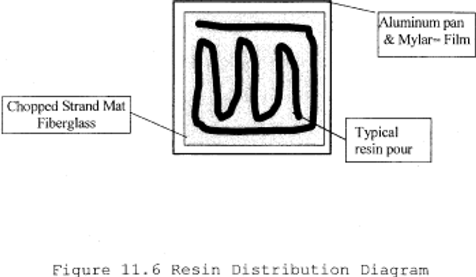
11.6.2 The resin is to be evenly distributed across the entire surface of the chopped strand mat using the resin application roller to achieve a wet look across the surface of the laminate. Pushing excess resin off the reinforcement and onto the Mylar sheet should be avoided. No resin is to be pushed more than 1/2 inch beyond the edge of the glass mat. If excess resin is pushed further from the glass mat, it will void the test run. As part of this process, typical visible air voids are to be eliminated by the rollout process. If the pour pattern is different from the above, it must be recorded and attached to test data sheet 17.1.
12. Data Analysis and Calculations
12.1 Data Analysis:
This test method requires a simple mass balance calculation, no special data analysis is necessary.
12.2 Calculations:
12.2.1 The target glass content (percent) for unfilled resin systems is determined from the specific production parameters being evaluated. In absence of any specific production requirements the target may be set at the tester's discretion.
12.2.2 Glass content determination (expressed as a per cent):
% Glass = Glass wt(g)/(Glass wt(g) Resin weight (g))
12.2.3 Weight of resin required:
Resin weight required = (Glass wt (g)/% glass) - Glass wt (g)
12.2.4 Filled resin formulation determination for filled resin systems (e.g. >30 percent filler by weight for a particulate filler, or >1 percent by weight for a lightweight filler, such as hollow microspheres):
% Resin content = resin
weight(g)/(resin weight(g) glass
weight(g) filler weight(g))
% Glass content = glass
weight(g)/(resin weight(g) glass
weight(g) filler weight(g))
Filler content = filler
weight(g)/(resin weight(g) glass
weight(g) filler weight(g))
12.2.5 Initiator weight determination:
Initiator weight (g) = Resin weight(g) × Initiator %
12.2.6 Emission weight loss determination:
Emissions weight loss (g) = Initial resin weight (g)?Final resin weight (g)
12.2.7 % Emission weight loss:
% Emission Weight Loss = (Emission weight loss (g) Initial resin weight (g) × 100
12.2.8 Average % Emission Weight Loss (assuming six test runs):

12.2.9 VSE Factor calculation:
VSE Factor = 1 ?(Average % VS Emission Weight Loss/Average NVS Emission Weight Loss)
| Test # | % VS weight loss | % NVS weight loss |
|---|---|---|
| 1 | 6.87 | 10.86 |
| 2 | 6.76 | 11.23 |
| 3 | 5.80 | 12.02 |
| 4 | 5.34 | 11.70 |
| 5 | 6.11 | 11.91 |
| 6 | 6.61 | 10.63 |
| Average Weight Loss | 6.25 | 11.39 |
| VSE Factor | 0.4 |
VSE Factor = 0.45
VSE Factor is used as input into the appropriate equation in Table 1 to this subpart.
Example from Table 1 to this subpart:
Manual Resin Application, 35 percent HAP resin, VSE Factor of 0.45
HAP Emissions with vapor suppresants = ((0.286 × %HAP)?0.0529) × 2000 × (1-(0.5 × VSE factor))
HAP Emissions with vapor suppresants = ((0.286 × .35)?0.0529) × 2000 × (1?(0.5 × .45))
HAP Emissions with vapor suppresants = 73 pounds of HAP emissions per ton of resin.
13. Method Performance
13.1 Bias:
The bias of this test method has not been determined.
13.2 Precision Testing
13.2.1 Subsequent to the initial development of this test protocol by the Composites Fabricators Association, a series of tests were conducted in three different laboratory facilities. The purpose of this round robin testing was to verify the precision of the test method in various laboratories. Each laboratory received a sample of an orthophthalic polyester resin from the same production batch, containing 48 per cent styrene by weight. Each testing site was also provided with the same vapor suppressant additive. The suppressant manufacturer specified the percentage level of suppressant additive. The resin manufacturer specified the type and level of initiator required to produce a 20 minute gel time. The target glass content was 30 percent by weight.
13.2.2 Each laboratory independently conducted the VSE test according to this method. A summary of the results is included in Table 13.1.
| Test Lab 1 | Test Lab 2 | Test Lab 3 | ||||
|---|---|---|---|---|---|---|
| NVS | VS | NVS | S | NVS | VS | |
| Average percent WT Loss | 4.24 | 1.15 | 4.69 | 1.84 | 5.73 | 1.61 |
| Standard Deviation | 0.095 | 0.060 | 0.002 | 0.002 | 0.020 | 0.003 |
| VSE Factor | 0.730 | 0.607 | 0.720 | |||
13.3 Comparison to EPA Reference Methods This test has no corresponding EPA reference method.
14. Pollution Prevention
The sample size used in this method produces a negligible emission of HAP, and has an insignificant impact upon the atmosphere.
15. Waste Management
The spent and waste materials generated during this test are disposed according to required facility procedures, and waste management recommendations on the corresponding material safety data sheets.
16. References and footnotes
16.1 Footnotes:
1 Balance Enclosure - The purpose of the balance enclosure is to prevent localized airflow from adversely affecting the laboratory balance. The enclosure may be a simple three-sided box with a top and an open face. The configuration of the enclosure is secondary to the purpose of providing a stable and steady balance reading, free from the effects of airflow, for accurate measurements. The enclosure can be fabricated locally. A typical enclosure is shown in Figure 17.1.
2 Laboratory Balance - Ohaus Precision Standard Series P/N TS400D or equivalent - Paul N. Gardner Co. 316 NE 1st St. Pompano Beach, FL 33060 or other suppliers.
3 Stop Watch - Local supply.
4 Thermometer - Mercury thermometer - ASTM No. 21C or equivalent; Digital thermometer - P/N TH-33033 or equivalent - Paul N. Gardner Co. 316 NE 1st St. Pompano Beach, FL 33060 or other suppliers.
5 Aluminum Pan - Local supply.
6 Mylar - Local supply.
7 Double Sided Tape - 3M Double Stick Tape or equivalent, local supply.
8 Laboratory Beakers - 250 to 400ml capacity - Local laboratory supply.
9 Eye Dropper or Pipette - Local laboratory supply.
10 Disposable Resin Application Roller Source - Wire Handle Roller P/N 205-050-300 or Plastic Handle Roller P/N 215-050-300 or equivalent; ES Manufacturing Inc., 2500 26st Ave. North, St. Petersburg, FL 33713, www.esmfg.com, or other source. Refer to Figure 17.3.
11 Hygrometer or Psychrometer - Model# THWD-1, or equivalent - Part # 975765 by Amprobe Instrument, 630 Merrick Road, P.O. Box 329, Lynbrook, NY 11563, 516-593-5600
12 Insulating Board (Teflon, cardboard, foam board etc.) - Local supply.
13 Laboratory Balance With Digital Output - Ohaus Precision Standard Series P/N TS120S or equivalent - Paul N. Gardner Co. 316 NE 1st St. Pompano Beach, FL 33060 or other suppliers.
14 Chopped Strand Mat - 1.5 oz/ft 2 Sources: Owens Corning Fiberglas - Fiberglas M-723; PPG Industries - ABM HTX; Vetrotex America - M-127 or equivalent.
15 Certificate of Analysis: Resin gel time, as recorded on the resin certificate of analysis, is measured using a laboratory standard gel time procedure. This procedure typically uses a 100 gram cup sample at 77°F (25°C), a specific type of initiator and a specified percentage.
16 Roll-out times may vary with resin viscosity or resin additive. The important aspect of this step is to produce the same roll-out time for both the suppressed and non-suppressed samples.
17 While this test can be used with filled resin systems, the test is not designed to determine the effect of the filler on emissions, but rather to measure the effect of the suppressant additive in the resin system. When evaluating a filled system both the non-vapor suppressed and vapor suppressed samples should be formulated with the same type and level of filler.
16.2 References
1. Phase 1 - Baseline Study Hand Lay-up, CFA, 1996
2. CFA Vapor Suppressant Effectiveness Test Development, 4/3/98, correspondence with Dr. Madeleine Strum, EPA, OAQPS
3. CFA Vapor Suppressant Effectiveness Screening Tests, 4/4/98
4. Styrene Suppressant Systems Study, Reichhold Chemical, 11/30/98
5. Evaluation of the CFA's New Proposed Vapor Suppressant Effectiveness Test, Technical Service Request #: ED-01-98, BYK Chemie, 6/3/98
6. Second Evaluation of the CFA's New Proposed Vapor Suppressant Effectiveness Test, Technical Service Request #: ED-02-98, BYK Chemie, 1/26/99
17. Data Sheets and Figures
17.1 This data sheet, or a similar data sheet, is used to record the test data for filled, unfilled, suppressed and non-suppressed tests. If additional time is required, the data sheet may be extended.
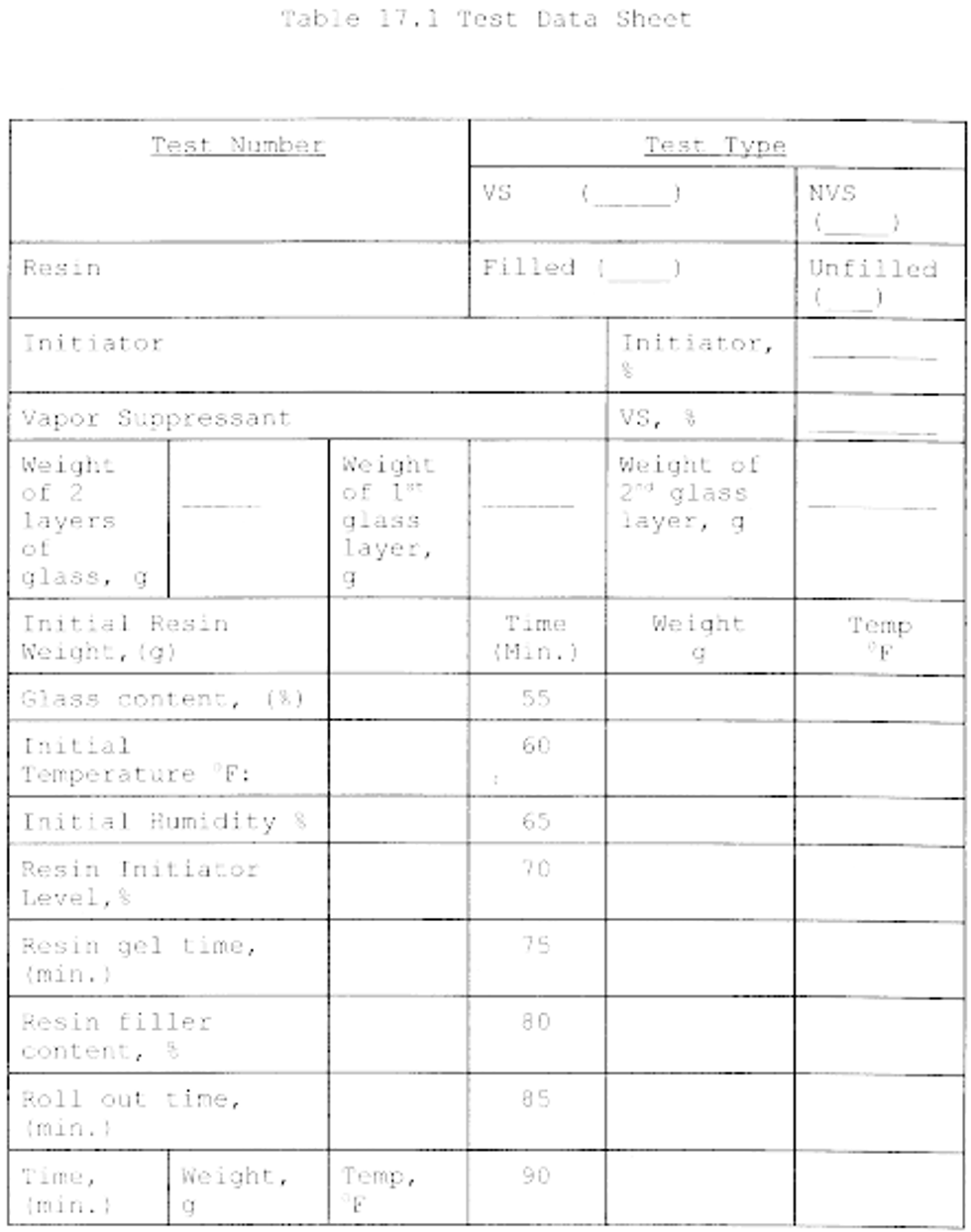
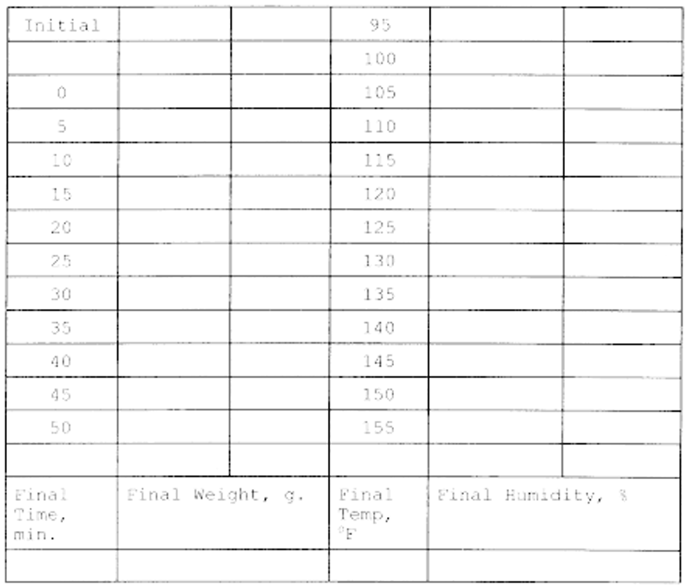
17.2 Data Acceptance Criteria Worksheet:
The following worksheet is used to determine the quality of collected data (i.e. insure the data collected all meets acceptance criteria)
| Test No. | Temperature | Laminate roll out time, min | Relative humidity, % | Resin weight, (g) | Glass content, % | Resin distribution | Meets criteria Y/N | |||
|---|---|---|---|---|---|---|---|---|---|---|
| Min | Max | Delta | Initial | Final | ||||||
| 1 | ||||||||||
| 2 | ||||||||||
| 3 | ||||||||||
| 4 | ||||||||||
| 5 | ||||||||||
| 6 | ||||||||||
| 7 | ||||||||||
| 8 | ||||||||||
| 9 | ||||||||||
| 10 | ||||||||||
| 11 | ||||||||||
| 12 | ||||||||||
| Average | ||||||||||
| Criteria | ±2°F | ±10% of Average | ±15 of Average | ±15 of Average | ±10% of Avg. | ±10% of Avg. | < 1/2 inch off mat | All Y | ||
17.3 VSE Factor Calculation
| Vapor suppressed | Non-vapor suppressed | ||
|---|---|---|---|
| Test # | % Weight loss | Test # | % Weight loss |
| VSE Factor = 1 - (% Average Weight Loss VS/ % Average Weight LossNVS) | |||
| Average Weight Loss | |||
| VSE Factor | |||
17.4 Figures
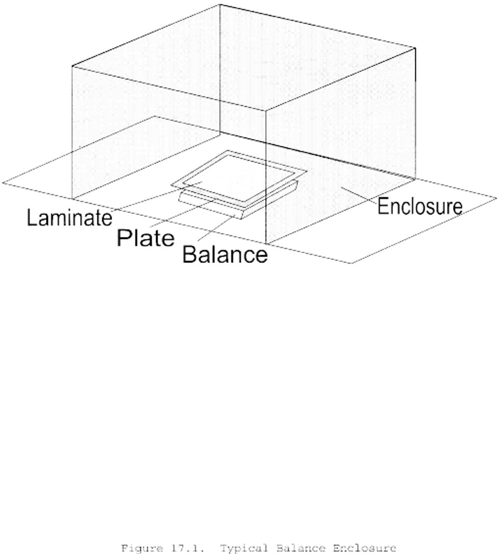
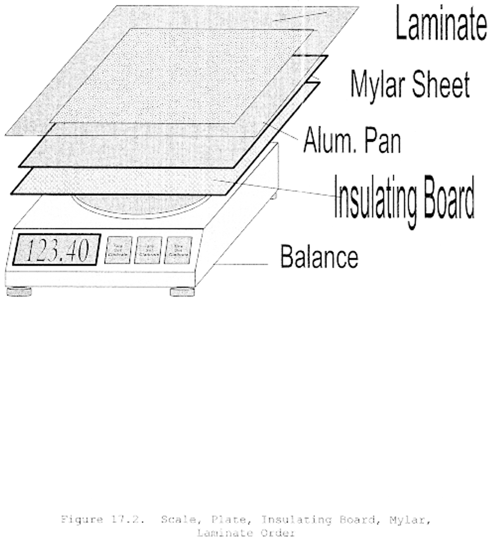
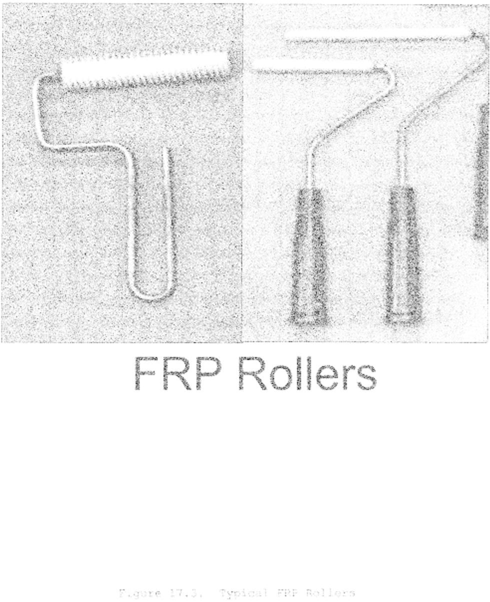
Source: 66 FR 44232, Aug. 22, 2001, unless otherwise noted.
['Air Programs']
['Hazardous Air Pollutants']
UPGRADE TO CONTINUE READING