Compliance Just Got Easier: Stay ahead of regulatory changes with instant notifications on updates that matter.
['Air Programs']
['Hazardous Air Pollutants']
07/04/2025

Copyright 2026 J. J. Keller & Associate, Inc. For re-use options please contact copyright@jjkeller.com or call 800-558-5011.
(a) You must conduct each performance test required by §63.4340 or §63.4350 according to the requirements in this section, unless you obtain a waiver of the performance test according to the provisions in §63.7(h).
(1) Representative web coating/printing or dyeing/finishing operation operating conditions. You must conduct the performance test under representative operating conditions for the web coating/printing or dyeing/finishing operation. Operations during periods of startup, shutdown, or nonoperation do not constitute representative conditions for purposes of conducting a performance test. The owner or operator may not conduct performance tests during periods of malfunction. You must record the process information that is necessary to document operating conditions during the test and explain why the conditions represent normal operation. Upon request, you must make available to the Administrator such records as may be necessary to determine the conditions of performance tests.
(2) Representative emission capture system and add-on control device operating conditions. You must conduct the performance test when the emission capture system and add-on control device are operating at a representative flow rate, and the add-on control device is operating at a representative inlet concentration. You must record information that is necessary to document emission capture system and add-on control device operating conditions during the test and explain why the conditions represent normal operation.
(b) You must conduct each performance test of an emission capture system according to the requirements in §63.4361. You must conduct each performance test of an add-on control device according to the requirements in §63.4362.
[68 FR 32189, May 29, 2003, as amended at 84 FR 9630, Mar. 15, 2019]
You must use the procedures and test methods in this section to determine capture efficiency as part of the performance test required by §63.4340 or §63.4350.
(a) Assuming 100 percent capture efficiency. You may assume the capture system efficiency is 100 percent if both of the conditions in paragraphs (a)(1) and (2) of this section are met.
(1) The capture system meets the criteria in Method 204 of appendix M to 40 CFR part 51 for a PTE and directs all the exhaust gases from the enclosure to an add-on control device.
(2) All regulated materials applied in the web coating/printing or dyeing/finishing operation are applied within the capture system; regulated material solvent flash-off, curing, and drying occurs within the capture system; and the removal or evaporation of cleaning materials from the web coating/printing operation surfaces they are applied to occurs within the capture system. For example, this criterion is not met if the web enters the open shop environment when moving between the application station and a curing oven.
(b) Measuring capture efficiency. If the capture system does not meet both of the criteria in paragraphs (a)(1) and (2) of this section, then you must use one of the three protocols described in paragraphs (c), (d), and (e) of this section to measure capture efficiency. The capture efficiency measurements use TVH capture efficiency as a surrogate for organic HAP capture efficiency. For the protocols in paragraphs (c) and (d) of this section, the capture efficiency measurement must consist of three test runs. Each test run must be at least 3 hours duration or the length of a production run, up to 8 hours.
(c) Liquid-to-uncaptured-gas protocol using a temporary total enclosure or building enclosure. The liquid-to-uncaptured-gas protocol compares the mass of liquid TVH in regulated materials applied in the web coating/printing or dyeing/finishing operation to the mass of TVH emissions not captured by the emission capture system. Use a temporary total enclosure or a building enclosure and the procedures in paragraphs (c)(1) through (6) of this section to measure emission capture system efficiency using the liquid-to-uncaptured-gas protocol.
(1) Either use a building enclosure or construct an enclosure around the web coating/printing or dyeing/finishing operation where regulated materials are applied, and all areas where emissions from these applied regulated materials subsequently occur, such as flash-off, curing, and drying areas. The areas of the web coating/printing or dyeing/finishing operation where capture devices collect emissions for routing to an add-on control device, such as the entrance and exit areas of an oven or tenter frame, must also be inside the enclosure. The enclosure must meet the applicable definition of a temporary total enclosure or building enclosure in Method 204 of appendix M to 40 CFR part 51.
(2) Use Method 204A or 204F of appendix M to 40 CFR part 51 to determine the mass fraction of TVH liquid input from each regulated material used in the web coating/printing or dyeing/finishing operation during each capture efficiency test run. To make the determination, substitute TVH for each occurrence of the term volatile organic compounds (VOC) in the methods.
(3) Use Equation 1 of this section to calculate the total mass of TVH liquid input from all the regulated materials applied in the web coating/printing or dyeing/finishing operation during each capture efficiency test run.

Where:
TVHapplied = Mass of liquid TVH in regulated materials applied in the web coating/printing or dyeing/finishing operation during the capture efficiency test run, kg.
TVHi = Mass fraction of TVH in regulated material, i, that is applied in the web coating/printing or dyeing/finishing operation during the capture efficiency test run, kg TVH per kg material.
Mi = Total mass of regulated material, i, applied in the web coating/printing or dyeing/finishing operation during the capture efficiency test run, kg.
n = Number of different regulated materials applied in the web coating/printing or dyeing/finishing operation during the capture efficiency test run.
(4) Use Method 204D or E of appendix M to 40 CFR part 51 to measure the total mass, kg, of TVH emissions that are not captured by the emission capture system; they are measured as they exit the temporary total enclosure or building enclosure during each capture efficiency test run. To make the measurement, substitute TVH for each occurrence of the term VOC in the methods.
(i) Use Method 204D if the enclosure is a temporary total enclosure.
(ii) Use Method 204E if the enclosure is a building enclosure. During the capture efficiency measurement, all organic compound-emitting operations inside the building enclosure, other than the web coating/printing or dyeing/finishing operation for which capture efficiency is being determined, must be shut down, but all fans and blowers must be operating normally.
(5) For each capture efficiency test run, determine the percent capture efficiency of the emission capture system using Equation 2 of this section:
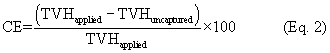
Where:
CE = Capture efficiency of the emission capture system vented to the add-on control device, percent.
TVHapplied = Total mass of TVH liquid input applied in the web coating/printing or dyeing/finishing operation during the capture efficiency test run, kg.
TVHuncaptured = Total mass of TVH that is not captured by the emission capture system and that exits from the temporary total enclosure or building enclosure during the capture efficiency test run, kg.
(6) Determine the capture efficiency of the emission capture system as the average of the capture efficiencies measured in the three test runs.
(d) Gas-to-gas protocol using a temporary total enclosure or a building enclosure. The gas-to-gas protocol compares the mass of TVH emissions captured by the emission capture system to the mass of TVH emissions not captured. Use a temporary total enclosure or a building enclosure and the procedures in paragraphs (d)(1) through (5) of this section to measure emission capture system efficiency using the gas-to-gas protocol.
(1) Either use a building enclosure or construct an enclosure around the web coating/printing or dyeing/finishing operation where regulated materials are applied, and all areas where emissions from these applied regulated materials subsequently occur, such as flash-off, curing, and drying areas. The areas of the web coating/printing or dyeing/finishing operation where capture devices collect emissions generated by the web coating/printing or dyeing/finishing operation for routing to an add-on control device, such as the entrance and exit areas of an oven or a tenter frame, must also be inside the enclosure. The enclosure must meet the applicable definition of a temporary total enclosure or building enclosure in Method 204 of appendix M to 40 CFR part 51.
(2) Use Method 204B or 204C of appendix M to 40 CFR part 51 to measure the total mass, kg, of TVH emissions captured by the emission capture system during each capture efficiency test run as measured at the inlet to the add-on control device. To make the measurement, substitute TVH for each occurrence of the term VOC in the methods.
(i) The sampling points for the Method 204B or 204C measurement must be upstream from the add-on control device and must represent total emissions routed from the capture system and entering the add-on control device.
(ii) If multiple emission streams from the capture system enter the add-on control device without a single common duct, then the emissions entering the add-on control device must be simultaneously measured in each duct and the total emissions entering the add-on control device must be determined.
(3) Use Method 204D or 204E of appendix M to 40 CFR part 51 to measure the total mass, kg, of TVH emissions that are not captured by the emission capture system; they are measured as they exit the temporary total enclosure or building enclosure during each capture efficiency test run. To make the measurement, substitute TVH for each occurrence of the term VOC in the methods.
(i) Use Method 204D if the enclosure is a temporary total enclosure.
(ii) Use Method 204E if the enclosure is a building enclosure. During the capture efficiency measurement, all organic compound-emitting operations inside the building enclosure, other than the web coating/printing or dyeing/finishing operation for which capture efficiency is being determined, must be shut down, but all fans and blowers must be operating normally.
(4) For each capture efficiency test run, determine the percent capture efficiency of the emission capture system using Equation 3 of this section:
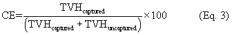
Where:
CE = Capture efficiency of the emission capture system vented to the add-on control device, percent.
TVHcaptured = Total mass of TVH captured by the emission capture system as measured at the inlet to the add-on control device during the emission capture efficiency test run, kg.
TVHuncaptured = Total mass of TVH that is not captured by the emission capture system and that exits from the temporary total enclosure or building enclosure during the capture efficiency test run, kg.
(5) Determine the capture efficiency of the emission capture system as the average of the capture efficiencies measured in the three test runs.
(e) Alternative capture efficiency protocol. As an alternative to the procedures specified in paragraphs (c) and (d) of this section, you may determine capture efficiency using any other capture efficiency protocol and test methods that satisfy the criteria of either the DQO or LCL approach as described in appendix A to subpart KK of this part.
You must use the procedures and test methods in this section to determine the add-on control device emission destruction or removal efficiency as part of the performance test required by §§63.4340 and 63.4350. You must conduct three test runs as specified in §63.7(e)(3) and each test run must last at least 1 hour.
(a) For all types of add-on control devices, use the test methods as specified in paragraphs (a)(1) through (5) of this section.
(1) Use Method 1 or 1A in appendix A-1 of part 60, as appropriate, to select sampling sites and velocity traverse points.
(2) Use Method 2, 2A, 2C, 2D, or 2F in appendix A-1, or Method 2G in appendix A-2, of part 60, as appropriate, to measure gas volumetric flow rate.
(3) Use Method 3, 3A, or 3B in appendix A of part 60, as appropriate, for gas analysis to determine dry molecular weight. You may also use as an alternative to Method 3B, the manual method for measuring the oxygen, carbon dioxide, and carbon monoxide content of exhaust gas in ANSI/ASME, PTC 19.10-1981, “Flue and Exhaust Gas Analyses [Part 10, Instruments and Apparatus]” (incorporated by reference, see §63.14).
(4) Use Method 4 in appendix A of part 60 to determine stack gas moisture.
(5) Methods for determining gas volumetric flow rate, dry molecular weight, and stack gas moisture must be performed, as applicable, during each test run.
(b) Measure the volatile organic matter concentration as carbon at the inlet and outlet of the add-on control device simultaneously, using Method 25 or 25A in appendix A-7 of part 60. If you are demonstrating compliance with the oxidizer outlet organic HAP concentration limit, only the outlet volatile organic matter concentration must be determined. The outlet volatile organic matter concentration is determined as the average of the three test runs. You may use Method 18 in appendix A-6 of part 60 to subtract methane emissions from measured volatile organic matter concentration as carbon.
(1) Use Method 25 if the add-on control device is an oxidizer and you expect the total gaseous organic concentration as carbon to be more than 50 parts per million (ppm) at the control device outlet.
(2) Use Method 25A if the add-on control device is an oxidizer and you expect the total gaseous organic concentration as carbon to be 50 ppm or less at the control device outlet. Method 25A must be used to demonstrate compliance with the oxidizer outlet organic HAP concentration limit.
(3) Use Method 25A if the add-on control device is not an oxidizer.
(c) If two or more add-on control devices are used for the same emission stream, then you must measure emissions at the outlet to the atmosphere of each device. For example, if one add-on control device is a concentrator with an outlet to the atmosphere for the high-volume, dilute stream that has been treated by the concentrator, and a second add-on control device is an oxidizer with an outlet to the atmosphere for the low-volume, concentrated stream that is treated with the oxidizer, you must measure emissions at the outlet of the oxidizer and the high volume dilute stream outlet of the concentrator.
(d) For each test run, determine the total gaseous organic emissions mass flow rates for the inlet and the outlet of the add-on control device, using Equation 1 of this section. If there is more than one inlet or outlet to the add-on control device, you must calculate the total gaseous organic mass flow rate using Equation 1 of this section for each inlet and each outlet and then total all of the inlet emissions and total all of the outlet emissions:

Where:
Mf = Total gaseous organic emissions mass flow rate, kg/hour (h).
Cc = Concentration of organic compounds as carbon in the vent gas, as determined by Method 25 or Method 25A, ppmv, dry basis.
Qsd = Volumetric flow rate of gases entering or exiting the add-on control device, as determined by Method 2, 2A, 2C, 2D, 2F, or 2G, dry standard cubic meters/hour (dscm/h).
0.0416 = Conversion factor for molar volume, kg-moles per cubic meter (mole/m 3) (@ 293 Kelvin (K) and 760 millimeters of mercury (mmHg)).
(e) For each test run, determine the add-on control device organic emissions destruction or removal efficiency using Equation 2 of this section.
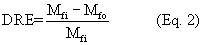
Where:
DRE = Organic emissions destruction or removal efficiency of the add-on control device, percent.
Mfi = Total gaseous organic emissions mass flow rate at the inlet(s) to the add-on control device, using Equation 1 of this section, kg/h.
Mfo = Total gaseous organic emissions mass flow rate at the outlet(s) of the add-on control device, using Equation 1 of this section, kg/h.
(f) Determine the emission destruction or removal efficiency of the add-on control device as the average of the efficiencies determined in the three test runs and calculated in Equation 2 of this section.
[68 FR 32189, May 29, 2003, as amended at 84 FR 9630, Mar. 15, 2019]
During the performance test required by §63.4340 or §63.4350 and described in §§63.4360, 63.4361, and 63.4362, you must establish the operating limits required by §63.4292 according to this section, unless you have received approval for alternative monitoring and operating limits under §63.8(f) as specified in §63.4292.
(a) Thermal oxidizers. If your add-on control device is a thermal oxidizer, establish the operating limits according to paragraphs (a)(1) and (2) of this section.
(1) During the performance test, you must monitor and record the temperature at least once every 15 minutes during each of the three test runs. You must monitor the temperature in the firebox of the thermal oxidizer or immediately downstream of the firebox before any substantial heat exchange occurs.
(2) Use the data collected during the performance test to calculate and record the average temperature maintained during the performance test. This average temperature is the minimum operating limit for your thermal oxidizer.
(b) Catalytic oxidizers. If your add-on control device is a catalytic oxidizer, establish the operating limits according to either paragraphs (b)(1) and (2) or paragraphs (b)(3) and (4) of this section.
(1) During the performance test, you must monitor and record the temperature at the inlet to the catalyst bed and the temperature difference across the catalyst bed at least once every 15 minutes during each of the three test runs.
(2) Use the data collected during the performance test to calculate and record the average temperature at the inlet to the catalyst bed and the average temperature difference across the catalyst bed maintained during the performance test. These are the minimum operating limits for your catalytic oxidizer.
(3) As an alternative to monitoring the temperature difference across the catalyst bed, you may monitor the temperature at the inlet to the catalyst bed and implement a site-specific inspection and maintenance plan for your catalytic oxidizer as specified in paragraph (b)(4) of this section. During the performance test, you must monitor and record the temperature just before the catalyst bed at least once every 15 minutes during each of the three test runs. Use the data collected during the performance test to calculate and record the average temperature just before the catalyst bed during the performance test. This is the minimum operating limit for your catalytic oxidizer.
(4) You must develop and implement an inspection and maintenance plan for your catalytic oxidizer(s) for which you elect to monitor according to paragraph (b)(3) of this section. The plan must address, at a minimum, the elements specified in paragraphs (b)(4)(i) through (iii) of this section.
(i) Annual sampling and analysis of the catalyst activity (i.e., conversion efficiency) following the manufacturer's or catalyst supplier's recommended procedures.
(ii) Monthly inspection of the oxidizer system, including the burner assembly and fuel supply lines for problems and, as necessary, adjust the equipment to assure proper air-to-fuel mixtures.
(iii) Annual internal and monthly external visual inspection of the catalyst bed to check for channeling, abrasion, and settling. If problems are found, you must take corrective action consistent with the manufacturer's recommendations and conduct a new performance test to determine destruction efficiency according to §63.4362.
(a) General. If you are using a control device to comply with the emission standards in §63.4290, you must install, operate, and maintain each CPMS specified in paragraphs (c) and (d) and (e) of this section according to the requirements in paragraphs (a)(1) through (8) of this section. You must install, operate, and maintain each CPMS specified in paragraph (b) of this section according to paragraphs (a)(5) through (7) of this section.
(1) Each CPMS must complete a minimum of one cycle of operation for each successive 15-minute period. You must have a minimum of four equally spaced successive cycles of CPMS operation to have a valid hour of data.
(2) You must have valid data from at least 90 percent of the hours during which the process operated.
(3) You must determine the hourly average of all recorded readings according to paragraphs (a)(3)(i) and (ii) of this section.
(i) To calculate a valid hourly value, you must have at least three of four equally spaced data values from that hour from a continuous monitoring system (CMS) that is not out-of-control.
(ii) Provided all of the readings recorded in accordance with paragraph (a)(3) of this section clearly demonstrate continuous compliance with the standard that applies to you, then you are not required to determine the hourly average of all recorded readings.
(4) You must determine the rolling 3-hour average of all recorded readings for each operating period. To calculate the average for each 3-hour averaging period, you must have at least two of three of the hourly averages for that period using only average values that are based on valid data (i.e., not from out-of-control periods).
(5) You must record the results of each inspection, calibration, and validation check of the CPMS.
(6) At all times, you must maintain the monitoring system in accordance with §63.4300(b) and in proper working order including, but not limited to, keeping readily available necessary parts for routine repairs of the monitoring equipment.
(7) Before September 12, 2019, except for monitoring malfunctions, associated repairs, or required quality assurance or control activities (including calibration checks or required zero and span adjustments), you must conduct all monitoring at all times that the unit is operating. On and after September 12, 2019, you must operate the CPMS and collect emission capture system and add-on control device parameter data at all times in accordance with §63.4300(b). Data recorded during monitoring malfunctions, associated repairs, out-of-control periods, or required quality assurance or control activities shall not be used for purposes of calculating the emissions concentrations and percent reductions specified in Table 1 to this subpart. You must use all the data collected during all other periods in assessing compliance of the control device and associated control system. A monitoring malfunction is any sudden, infrequent, not reasonably preventable failure of the monitoring system to provide valid data. Monitoring failures that are caused in part by poor maintenance or careless operation are not malfunctions.
(8) Except for periods of required quality assurance or control activities, any averaging period during which the CPMS fails to operate and record data continuously as required by paragraph (a)(1) of this section, or during which generated data cannot be included in calculating averages as specified in paragraph (a)(7) of this section, constitutes a deviation, and you must notify the Administrator in accordance with §63.4311(a).
(b) Capture system bypass line. You must meet the requirements of paragraphs (a)(5) through (6) and (b)(1) and (2) of this section for each emission capture system that contains bypass lines that could divert emissions away from the add-on control device to the atmosphere.
(1) You must monitor or secure the valve or closure mechanism controlling the bypass line in a nondiverting position in such a way that the valve or closure mechanism cannot be opened without creating a record that the valve was opened. The method used to monitor or secure the valve or closure mechanism must meet one of the requirements specified in paragraphs (b)(1)(i) through (iv) of this section.
(i) Flow control position indicator. Install, calibrate, maintain, and operate according to the manufacturer's specifications a flow control position indicator that takes a reading at least once every 15 minutes and provides a record indicating whether the emissions are directed to the add-on control device or diverted from the add-on control device. The time of occurrence and flow control position must be recorded, as well as every time the flow direction is changed. The flow control position indicator must be installed at the entrance to any bypass line that could divert the emissions away from the add-on control device to the atmosphere.
(ii) Car-seal or lock-and-key valve closures. Secure any bypass line valve in the closed position with a car-seal or a lock-and-key type configuration. You must visually inspect the seal or closure mechanism at least once every month to ensure that the valve is maintained in the closed position, and the emissions are not diverted away from the add-on control device to the atmosphere.
(iii) Valve closure continuous monitoring. Ensure that any bypass line valve is in the closed (non-diverting) position through monitoring of valve position at least once every 15 minutes. You must inspect the monitoring system at least once every month to verify that the monitor will indicate valve position.
(iv) Automatic shutdown system. Use an automatic shutdown system in which the web coating/printing or dyeing/finishing operation is stopped when flow is diverted by the bypass line away from the add-on control device to the atmosphere when the web coating/printing or dyeing/finishing operation is running. You must inspect the automatic shutdown system at least once every month to verify that it will detect diversions of flow and shutdown the web coating/printing or dyeing/finishing operation.
(2) If any bypass line is opened, you must include a description of why the bypass line was opened and the length of time it remained open in the semiannual compliance reports required in §63.4311.
(c) Oxidizers. If you are using an oxidizer to comply with the emission standards, you must comply with paragraphs (c)(1) through (3) of this section.
(1) Install, calibrate, maintain, and operate temperature monitoring equipment according to the manufacturer's specifications. The calibration of the chart recorder, data logger, or temperature indicator must be verified every 3 months or the chart recorder, data logger, or temperature indicator must be replaced. A thermocouple is considered part of the temperature indicator for purposes of performing periodic calibration and verification checks.
(2) For an oxidizer other than a catalytic oxidizer, install, calibrate, operate, and maintain a temperature monitoring device equipped with a continuous recorder. The device must have an accuracy of ±1 percent of the temperature being monitored in degrees Celsius, or ±1°Celsius, whichever is greater. The thermocouple or temperature sensor must be installed in the combustion chamber at a location in the combustion zone.
(3) For a catalytic oxidizer, install, calibrate, operate, and maintain a temperature monitoring device equipped with a continuous recorder. The device must be capable of monitoring temperature with an accuracy of ±1 percent of the temperature being monitored in degrees Celsius or ±1 degree Celsius, whichever is greater. The thermocouple or temperature sensor must be installed in the vent stream at the nearest feasible point to the inlet and outlet of the catalyst bed. Calculate the temperature rise across the catalyst.
(d) Other types of control devices. If you use a control device other than an oxidizer or wish to monitor an alternative parameter and comply with a different operating limit, you must apply to the Administrator for approval of an alternative monitoring method under §63.8(f).
(e) Capture system monitoring. If you are complying with the emission standards in §63.4290 through the use of a capture system and control device, you must develop a site-specific monitoring plan containing the information specified in paragraphs (e)(1) and (2) of this section for these capture systems. You must monitor the capture system in accordance with paragraph (e)(3) of this section. You must make the monitoring plan available for inspection by the permitting authority upon request.
(1) The monitoring plan must:
(i) Identify the operating parameter to be monitored to ensure that the capture efficiency determined during the initial compliance test is maintained; and
(ii) Explain why this parameter is appropriate for demonstrating ongoing compliance; and
(iii) Identify the specific monitoring procedures.
(2) The monitoring plan must specify the operating parameter value or range of values that demonstrate compliance with the emission standards in §63.4290. The specified operating parameter value or range of values must represent the conditions present when the capture system is being properly operated and maintained.
(3) You must conduct all capture system monitoring in accordance with the plan.
(4) Any deviation from the operating parameter value or range of values which are monitored according to the plan will be considered a deviation from the operating limit.
(5) You must review and update the capture system monitoring plan at least annually.
[68 FR 32189, May 29, 2003, as amended at 84 FR 9630, Mar. 15, 2019]
['Air Programs']
['Hazardous Air Pollutants']
UPGRADE TO CONTINUE READING