
...
(a) New and reconstructed affected sources. For a new or reconstructed affected source, you must meet the requirements of paragraphs (a)(1) through (4) of this section.
(1) All emission capture systems, add-on control devices, and CPMS must be installed and operating no later than the applicable compliance date specified in §63.3083. You must conduct a performance test of each capture system and add-on control device according to §§63.3164 through 63.3166 and establish the operating limits required by §63.3093 no later than 180 days after the applicable compliance date specified in §63.3083.
(2) You must develop and begin implementing the work practice plans required by §63.3094(b) and (c) no later than the compliance date specified in §63.3083.
(3) You must complete the initial compliance demonstration for the initial compliance period according to the requirements of §63.3161. The initial compliance period begins on the applicable compliance date specified in §63.3083 and ends on the last day of the month following the compliance date. If the compliance date occurs on any day other than the first day of a month, then the initial compliance period extends through the end of that month plus the next month. You must determine the mass of organic HAP emissions and volume of coating solids deposited in the initial compliance period. The initial compliance demonstration includes the results of emission capture system and add-on control device performance tests conducted according to §§63.3164 through 63.3166; supporting documentation showing that during the initial compliance period the organic HAP emission rate was equal to or less than the emission limit in §63.3090(a); the operating limits established during the performance tests and the results of the continuous parameter monitoring required by §63.3168; and documentation of whether you developed and implemented the work practice plans required by §63.3094(b) and (c).
(4) You do not need to comply with the operating limits for the emission capture system and add-on control device required by §63.3093 until after you have completed the performance tests specified in paragraph (a)(1) of this section. Instead, you must maintain a log detailing the operation and maintenance of the emission capture system, add-on control device, and CPMS during the period between the compliance date and the performance test. You must begin complying with the operating limits for your affected source on the date you complete the performance tests specified in paragraph (a)(1) of this section.
(b) Existing affected sources. For an existing affected source, you must meet the requirements of paragraphs (b)(1) through (3) of this section.
(1) All emission capture systems, add-on control devices, and CPMS must be installed and operating no later than the applicable compliance date specified in §63.3083. You must conduct an initial performance test of each capture system and add-on control device according to the procedures in §§63.3164 through 63.3166 and establish the operating limits required by §63.3093 no later than the compliance date specified in §63.3083.
(2) You must develop and begin implementing the work practice plans required by §63.3094(b) and (c) no later than the compliance date specified in §63.3083.
(3) You must complete the initial compliance demonstration for the initial compliance period according to the requirements of §63.3161. The initial compliance period begins on the applicable compliance date specified in §63.3083 and ends on the last day of the month following the compliance date. If the compliance date occurs on any day other than the first day of a month, then the initial compliance period extends through the end of that month plus the next month. You must determine the mass of organic HAP emissions and volume of coating solids deposited during the initial compliance period. The initial compliance demonstration includes the results of emission capture system and add-on control device performance tests conducted according to §§63.3164 through 63.3166; supporting documentation showing that during the initial compliance period the organic HAP emission rate was equal to or less than the emission limits in §63.3091(a); the operating limits established during the performance tests and the results of the continuous parameter monitoring required by §63.3168; and documentation of whether you developed and implemented the work practice plans required by §63.3094(b) and (c).
(c) You are not required to conduct an initial performance test to determine capture efficiency or destruction efficiency of a capture system or control device if you receive approval to use the results of a performance test that has been previously conducted on that capture system (either a previous stack test or a previous panel test) or control device. You are not required to conduct an initial test to determine transfer efficiency if you receive approval to use the results of a test that has been previously conducted. Any such previous tests must meet the conditions described in paragraphs (c)(1) through (3) of this section.
(1) The previous test must have been conducted using the methods and conditions specified in this subpart.
(2) Either no process or equipment changes have been made since the previous test was performed or the owner or operator must be able to demonstrate that the results of the performance test reliably demonstrate compliance despite process or equipment changes.
(3) Either the required operating parameters were established in the previous test or sufficient data were collected in the previous test to establish the required operating parameters.
[85 FR 41129, July 8, 2020]
(a) You must meet all of the requirements of this section to demonstrate initial compliance. To demonstrate initial compliance, the organic HAP emissions from the combined electrodeposition primer, primer-surfacer, topcoat, final repair, glass bonding primer, and glass bonding adhesive operations plus all coatings and thinners, except for deadener materials and for adhesive and sealer materials that are not components of glass bonding systems, used in coating operations added to the affected source pursuant to §63.3082(c) must meet the applicable emission limitation in §63.3090(a) or §63.3091(a) and the applicable operating limits and work practice standards in §§63.3093 and 63.3094.
(b) Compliance with operating limits. Except as provided in §63.3160(a)(4), you must establish and demonstrate continuous compliance during the initial compliance period with the operating limits required by §63.3093, using the procedures specified in §§63.3167 and 63.3168.
(c) Compliance with work practice requirements. You must develop, implement, and document your implementation of the work practice plans required by §63.3094(b) and (c) during the initial compliance period, as specified in §63.3130.
(d) Compliance with emission limits. You must follow the procedures in paragraphs (e) through (o) of this section to demonstrate compliance with the applicable emission limit in §63.3090(a) or §63.3091(a). You may also use the guidelines presented in “Protocol for Determining the Daily Volatile Organic Compound Emission Rate of Automobile and Light-Duty Truck Primer-Surfacer and Topcoat” EPA-453/R-08-002 (incorporated by reference, see §63.14) in making this demonstration.
(e) Determine the mass fraction of organic HAP, density, and volume used. Follow the procedures specified in §63.3151(a) through (c) to determine the mass fraction of organic HAP and the density and volume of each coating and thinner used during each month. For electrodeposition primer operations, the mass fraction of organic HAP, density, and volume used must be determined for each material added to the tank or system during each month.
(f) Determine the volume fraction of coating solids for each coating. You must determine the volume fraction of coating solids (liter of coating solids per liter of coating) for each coating used during the compliance period by a test or by information provided by the supplier or the manufacturer of the material, as specified in paragraphs (f)(1) and (2) of this section. For electrodeposition primer operations, the volume fraction of solids must be determined for each material added to the tank or system during each month. If test results obtained according to paragraph (f)(1) of this section do not agree with the information obtained under paragraph (f)(2) of this section, the test results will take precedence unless, after consultation, the facility demonstrates to the satisfaction of the enforcement authority that the facility's data are correct.
(1) ASTM Method D2697-03 (Reapproved 2014) or ASTM Method D6093-97 (Reapproved 2016). You may use ASTM D2697-03 (Reapproved 2014) (incorporated by reference, see §63.14), or ASTM D6093-97 (Reapproved 2016) (incorporated by reference, see §63.14), to determine the volume fraction of coating solids for each coating. Divide the nonvolatile volume percent obtained with the methods by 100 to calculate volume fraction of coating solids.
(2) Information from the supplier or manufacturer of the material. You may obtain the volume fraction of coating solids for each coating from the supplier or manufacturer.
(g) Determine the transfer efficiency for each coating. You must determine the transfer efficiency for each primer-surfacer and topcoat coating, and for all coatings, except for deadener and for adhesive and sealer that are not components of glass bonding systems, used in coating operations added to the affected source pursuant to §63.3082(c) using ASTM Method D5066-91 (Reapproved 2017), “Standard Test Method for Determination of the Transfer Efficiency Under Production Conditions for Spray Application of Automotive Paints-Weight Basis” (incorporated by reference, see §63.14), or the guidelines presented in “Protocol for Determining the Daily Volatile Organic Compound Emission Rate of Automobile and Light-Duty Truck Primer-Surfacer and Topcoat” EPA-453/R-08-002 (incorporated by reference, see §63.14). You may conduct transfer efficiency testing on representative coatings and for representative spray booths as described in “Protocol for Determining the Daily Volatile Organic Compound Emission Rate of Automobile and Light-Duty Truck Primer-Surfacer and Topcoat” EPA-453/R-08-002 (incorporated by reference, see §63.14). You may assume 100 percent transfer efficiency for electrodeposition primer coatings, glass bonding primers, and glass bonding adhesives. For final repair coatings, you may assume 40 percent transfer efficiency for air atomized spray and 55 percent transfer efficiency for electrostatic spray and high volume, low pressure spray. For blackout, chip resistant edge primer, interior color, inline repair, lower body anti-chip coatings, or underbody anti-chip coatings, you may assume 40 percent transfer efficiency for air atomized spray, 55 percent transfer efficiency for electrostatic spray and high volume-low pressure spray, and 80 percent transfer efficiency for airless spray.
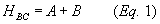
(h) Calculate the total mass of organic HAP emissions before add-on controls. Calculate the total mass of organic HAP emissions before consideration of add-on controls from all coatings and thinners used during each month in the combined electrodeposition primer, primer-surfacer, topcoat, final repair, glass bonding primer, and glass bonding adhesive operations plus all coatings and thinners, except for deadener materials and for adhesive and sealer materials that are not components of glass bonding systems, used in coating operations added to the affected source pursuant to §63.3082(c) using Equation 1 of this section:
Where:
HBC = Total mass of organic HAP emissions before consideration of add-on controls during the month, kg.
A = Total mass of organic HAP in the coatings used during the month, kg, as calculated in Equation 1A of this section.
B = Total mass of organic HAP in the thinners used during the month, kg, as calculated in Equation 1B of this section.
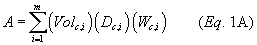
(1) Calculate the kg organic HAP in the coatings used during the month using Equation 1A of this section:
Where:
A = Total mass of organic HAP in the coatings used during the month, kg.
Volc, i = Total volume of coating, i, used during the month, liters.
Dc, i = Density of coating, i, kg coating per liter coating.
Wc, i = Mass fraction of organic HAP in coating, i, kg organic HAP per kg coating.
m = Number of different coatings used during the month.
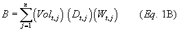
(2) Calculate the kg of organic HAP in the thinners used during the month using Equation 1B of this section:
Where:
B = Total mass of organic HAP in the thinners used during the month, kg.
Volt, j = Total volume of thinner, j, used during the month, liters.
Dt, j = Density of thinner, j, kg per liter.
Wt, j = Mass fraction of organic HAP in thinner, j, kg organic HAP per kg thinner.
n = Number of different thinners used during the month.
(i) Calculate the organic HAP emission reduction for each controlled coating operation. Determine the mass of organic HAP emissions reduced for each controlled coating operation during each month. The emission reduction determination quantifies the total organic HAP emissions captured by the emission capture system and destroyed or removed by the add-on control device. Use the procedures in paragraph (j) of this section to calculate the mass of organic HAP emission reduction for each controlled coating operation using an emission capture system and add-on control device other than a solvent recovery system for which you conduct liquid-liquid material balances. For each controlled coating operation using a solvent recovery system for which you conduct a liquid-liquid material balance, use the procedures in paragraph (k) of this section to calculate the organic HAP emission reduction.
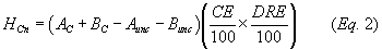
(j) Calculate the organic HAP emission reduction for each controlled coating operation not using liquid-liquid material balances. For each controlled coating operation using an emission capture system and add-on control device other than a solvent recovery system for which you conduct liquid-liquid material balances, calculate the mass of organic HAP emission reduction for the controlled coating operation, excluding all periods of time in which a deviation, including a deviation during a period of startup, shutdown, or malfunction, from an operating limit or from any CPMS requirement for the capture system or control device serving the controlled coating operation occurred, during the month using Equation 2 of this section. The calculation of mass of organic HAP emission reduction for the controlled coating operation during the month applies the emission capture system efficiency and add-on control device efficiency to the mass of organic HAP contained in the coatings and thinners that are used in the coating operation served by the emission capture system and add-on control device during each month. Except as provided in paragraph (p) of this section, for any period of time in which a deviation, including a deviation during a period of startup, shutdown, or malfunction, from an operating limit or from any CPMS requirement of the capture system or control device serving the controlled coating operation occurred, you must assume zero efficiency for the emission capture system and add-on control device. Equation 2 of this section treats the materials used during such a deviation as if they were used on an uncontrolled coating operation for the time period of the deviation.
Where:
HCn = Mass of organic HAP emission reduction, excluding all periods of time in which a deviation, including a deviation during a period of startup, shutdown, or malfunction, from an operating limit or from any CPMS requirement for the capture system or control device serving the controlled coating operation occurred, for the controlled coating operation during the month, kg.
AC = Total mass of organic HAP in the coatings used in the controlled coating operation during the month, kg, as calculated in Equation 2A of this section.
BC = Total mass of organic HAP in the thinners used in the controlled coating operation during the month, kg, as calculated in Equation 2B of this section.
Aunc = Total mass of organic HAP in the coatings used during all periods of time in which a deviation, including a deviation during a period of startup, shutdown, or malfunction, from an operating limit or from any CPMS requirement for the capture system or control device serving the controlled coating operation occurred for the controlled coating operation during the month, kg, as calculated in Equation 2C of this section.
Bunc = Total mass of organic HAP in the thinners used during all periods of time in which a deviation, including a deviation during a period of startup, shutdown, or malfunction, from an operating limit or from any CPMS requirement for the capture system or control device serving the controlled coating operation occurred for the controlled coating operation during the month, kg, as calculated in Equation 2D of this section.
CE = Capture efficiency of the emission capture system vented to the add-on control device, percent. Use the test methods and procedures specified in §§63.3164 and 63.3165 to measure and record capture efficiency.
DRE = Organic HAP destruction or removal efficiency of the add-on control device, percent. Use the test methods and procedures in §§63.3164 and 63.3166 to measure and record the organic HAP destruction or removal efficiency.
(1) Calculate the mass of organic HAP in the coatings used in the controlled coating operation, kg, using Equation 2A of this section.
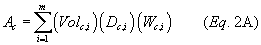
Where:
AC = Total mass of organic HAP in the coatings used in the controlled coating operation during the month, kg.
Volc, i = Total volume of coating, i, used during the month, liters.
Dc, i = Density of coating, i, kg per liter.
Wc, i = Mass fraction of organic HAP in coating, i, kg per kg.
m = Number of different coatings used.
(2) Calculate the mass of organic HAP in the thinners used in the controlled coating operation, kg, using Equation 2B of this section.
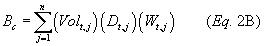
Where:
BC = Total mass of organic HAP in the thinners used in the controlled coating operation during the month, kg.
Volt, j = Total volume of thinner, j, used during the month, liters.
Dt, j = Density of thinner, j, kg per liter.
Wt, j = Mass fraction of organic HAP in thinner, j, kg per kg.
n = Number of different thinners used.
(3) Calculate the mass of organic HAP in the coatings used in the controlled coating operation during deviations specified in §63.3163(c) and (d), using Equation 2C of this section:
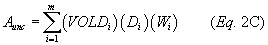
Where:
Aunc = Total mass of organic HAP in the coatings used during all periods of time in which a deviation, including a deviation during a period of startup, shutdown, or malfunction, from an operating limit or from any CPMS requirement for the capture system or control device serving the controlled coating operation occurred for the controlled coating operation during the month, kg.
VOLDi = Total volume of coating, i, used in the controlled coating operation during deviations, liters.
Di = Density of coating, i, kg per liter.
Wi = Mass fraction of organic HAP in coating, i, kg organic HAP per kg coating.
m = Number of different coatings.
(4) Calculate the mass of organic HAP in the thinners used in the controlled coating operation during deviations specified in §63.3163(c) and (d), using Equation 2D of this section:
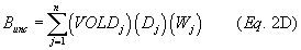
Where:
Bunc = Total mass of organic HAP in the thinners used during all periods of time in which a deviation, including a deviation during a period of startup, shutdown, or malfunction, from an operating limit or from any CPMS requirement for the capture system or control device serving the controlled coating operation occurred for the controlled coating operation during the month, kg.
VOLDj = Total volume of thinner, j, used in the controlled coating operation during deviations, liters.
Dj = Density of thinner, j, kg per liter.
Wh = Mass fraction of organic HAP in thinner, j, kg organic HAP per kg coating.
n = Number of different thinners.
(k) Calculate the organic HAP emission reduction for each controlled coating operation using liquid-liquid material balances. For each controlled coating operation using a solvent recovery system for which you conduct liquid-liquid material balances, calculate the mass of organic HAP emission reduction for the coating operation controlled by the solvent recovery system using a liquid-liquid material balance during the month by applying the volatile organic matter collection and recovery efficiency to the mass of organic HAP contained in the coatings and thinners used in the coating operation controlled by the solvent recovery system during each month. Perform a liquid-liquid material balance for each month as specified in paragraphs (k)(1) through (6) of this section. Calculate the mass of organic HAP emission reduction by the solvent recovery system as specified in paragraph (k)(7) of this section.
(1) For each solvent recovery system, install, calibrate, maintain, and operate according to the manufacturer's specifications, a device that indicates the cumulative amount of volatile organic matter recovered by the solvent recovery system each month. The device must be initially certified by the manufacturer to be accurate to within ±2.0 percent of the mass of volatile organic matter recovered.
(2) For each solvent recovery system, determine the mass of volatile organic matter recovered for the month, kg, based on measurement with the device required in paragraph (k)(1) of this section.
(3) Determine the mass fraction of volatile organic matter for each coating and thinner used in the coating operation controlled by the solvent recovery system during the month, kg volatile organic matter per kg coating. You may determine the volatile organic matter mass fraction using EPA Method 24 of 40 CFR part 60, appendix A-7, or an EPA approved alternative method, or you may use information provided by the manufacturer or supplier of the coating. In the event of any inconsistency between information provided by the manufacturer or supplier and the results of EPA Method 24 of 40 CFR part 60, appendix A-7, or an approved alternative method, the test method results will govern unless after consultation, the facility demonstrates to the satisfaction of the enforcement authority that the facility's data are correct.
(4) Determine the density of each coating and thinner used in the coating operation controlled by the solvent recovery system during the month, kg per liter, according to §63.3151(b).
(5) Measure the volume of each coating and thinner used in the coating operation controlled by the solvent recovery system during the month, liters.
(6) Each month, calculate the solvent recovery system's volatile organic matter collection and recovery efficiency, using Equation 3 of this section:
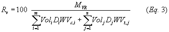
Where:
RV = Volatile organic matter collection and recovery efficiency of the solvent recovery system during the month, percent.
MVR = Mass of volatile organic matter recovered by the solvent recovery system during the month, kg.
Voli = Volume of coating, i, used in the coating operation controlled by the solvent recovery system during the month, liters.
Di = Density of coating, i, kg per liter.
WVc, i = Mass fraction of volatile organic matter for coating, i, kg volatile organic matter per kg coating.
Volj = Volume of thinner, j, used in the coating operation controlled by the solvent recovery system during the month, liters.
Dj = Density of thinner, j, kg per liter.
WVt, j = Mass fraction of volatile organic matter for thinner, j, kg volatile organic matter per kg thinner.
m = Number of different coatings used in the coating operation controlled by the solvent recovery system during the month.
n = Number of different thinners used in the coating operation controlled by the solvent recovery system during the month.
(7) Calculate the mass of organic HAP emission reduction for the coating operation controlled by the solvent recovery system during the month, using Equation 4 of this section:
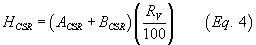
Where:
HCSR = Mass of organic HAP emission reduction for the coating operation controlled by the solvent recovery system using a liquid-liquid material balance during the month, kg.
ACSR = Total mass of organic HAP in the coatings used in the coating operation controlled by the solvent recovery system, kg, calculated using Equation 4A of this section.
BCSR = Total mass of organic HAP in the thinners used in the coating operation controlled by the solvent recovery system, kg, calculated using Equation 4B of this section.
RV = Volatile organic matter collection and recovery efficiency of the solvent recovery system, percent, from Equation 3 of this section.
(i) Calculate the mass of organic HAP in the coatings used in the coating operation controlled by the solvent recovery system, kg, using Equation 4A of this section.
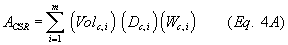
Where:
ACSR = Total mass of organic HAP in the coatings used in the coating operation controlled by the solvent recovery system during the month, kg.
Volc, i = Total volume of coating, i, used during the month in the coating operation controlled by the solvent recovery system, liters.
Dc, i = Density of coating, i, kg per liter.
Wc, i = Mass fraction of organic HAP in coating, i, kg per kg.
m = Number of different coatings used.
(ii) Calculate the mass of organic HAP in the thinners used in the coating operation controlled by the solvent recovery system, kg, using Equation 4B of this section.
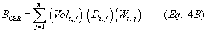
Where:
BCSR = Total mass of organic HAP in the thinners used in the coating operation controlled by the solvent recovery system during the month, kg.
Volt, j = Total volume of thinner, j, used during the month in the coating operation controlled by the solvent recovery system, liters.
Dt, j = Density of thinner, j, kg per liter.
Wt, j = Mass fraction of organic HAP in thinner, j, kg per kg.
n = Number of different thinners used.
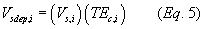
(l) Calculate the total volume of coating solids deposited. Determine the total volume of coating solids deposited, liters, in the combined electrodeposition primer, primer-surfacer, topcoat, final repair, glass bonding primer, and glass bonding adhesive operations plus all coatings and thinners, except for deadener materials and for adhesive and sealer materials that are not components of glass bonding systems used in coating operations added to the affected source pursuant to §63.3082(c) using Equation 5 of this section:
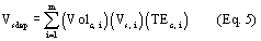
Where:
Vsdep = Total volume of coating solids deposited during the month, liters.
Volc,i = Total volume of coating, i, used during the month, liters.
Vs,i = Volume fraction of coating solids for coating, i, liter solids per liter coating, determined according to §63.3161(f).
TEc,i = Transfer efficiency of coating, i, determined according to §63.3161(g), expressed as a decimal, for example 60 percent must be expressed as 0.60.
M = Number of coatings used during the month.
(m) Calculate the mass of organic HAP emissions for each month. Determine the mass of organic HAP emissions, kg, during each month, using Equation 6 of this section.

Where:
HHAP = Total mass of organic HAP emissions for the month, kg.
HBC = Total mass of organic HAP emissions before add-on controls from all the coatings and thinners used during the month, kg, determined according to paragraph (h) of this section.
HCn, i = Total mass of organic HAP emission reduction for controlled coating operation, i, not using a liquid-liquid material balance, excluding all periods of time in which a deviation, including a deviation during a period of startup, shutdown, or malfunction, from an operating limit or from any CPMS requirement for the capture system or control device serving the controlled coating operation occurred, for the controlled coating operation during the month, from Equation 2 of this section.
HCSR, j = Total mass of organic HAP emission reduction for coating operation, j, controlled by a solvent recovery system using a liquid-liquid material balance, during the month, kg, from Equation 4 of this section.
HDEV, k, m = Mass of organic HAP emission reduction, based on the capture system and control device efficiency approved under paragraph (p) of this section for period of deviation, m, for controlled coating operation, k, kg, as determined using Equation 8 of this section.
q = Number of controlled coating operations not using a liquid-liquid material balance.
r = Number of coating operations controlled by a solvent recovery system using a liquid-liquid material balance.
Sk = Number of periods of deviation in the month for which non-zero capture and control device efficiencies have been approved for controlled coating operation, k.
(n) Calculate the organic HAP emission rate for the month. Determine the organic HAP emission rate for the month, kg organic HAP per liter coating solids deposited, using Equation 7 of this section:
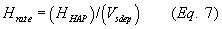
Where:
Hrate = Organic HAP emission rate for the month compliance period, kg organic HAP per liter coating solids deposited.
HHAP = Mass of organic HAP emissions for the month, kg, determined according to Equation 6 of this section.
Vsdep = Total volume of coating solids deposited during the month, liters, from Equation 5 of this section.
(o) Compliance demonstration. To demonstrate initial compliance, the organic HAP emissions from the combined electrodeposition primer, primer-surfacer, topcoat, final repair, glass bonding primer, and glass bonding adhesive operations plus all coatings and thinners, except for deadener materials and for adhesive and sealer materials that are not components of glass bonding systems, used in coating operations added to the affected source pursuant to §63.3082(c) must be less than or equal to the applicable emission limitation in §63.3090(a) or §63.3091(a). You must keep all records as required by §§63.3130 and 63.3131. As part of the Notification of Compliance Status required by §63.3110, you must submit a statement that the coating operation(s) was (were) in compliance with the emission limitations during the initial compliance period because the organic HAP emission rate was less than or equal to the applicable emission limit in §63.3090(a) or §63.3091(a) and you achieved the operating limits required by §63.3093 and the work practice standards required by §63.3094.
(p) You may request approval from the Administrator to use non-zero capture efficiencies and add-on control device efficiencies for any period of time in which a deviation, including a deviation during a period of startup, shutdown, or malfunction, from an operating limit or from any CPMS requirement for the capture system or add-on control device serving a controlled coating operation occurred.
(1) If you have manually collected parameter data indicating that a capture system or add-on control device was operating normally during a CPMS malfunction, a CPMS out-of-control period, or associated repair, then these data may be used to support and document your request to use the normal capture efficiency or add-on control device efficiency for that period of deviation.
(2) If you have data indicating the actual performance of a capture system or add-on control device (e.g., capture efficiency measured at a reduced flow rate or add-on control device efficiency measured at a reduced thermal oxidizer temperature) during a deviation, including a deviation during a period of startup, shutdown, or malfunction, from an operating limit or from any CPMS requirement for the capture system or add-on control device serving a controlled coating operation, then these data may be used to support and document your request to use these values for that period of deviation.
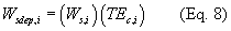
(3) The organic HAP emission reduction achieved during each period of deviation, including a deviation during a period of startup, shutdown, or malfunction, from an operating limit or from any CPMS requirement for the capture system or add-on control device serving a controlled coating operation for which the Administrator has approved the use of non-zero capture efficiency and add-on control device efficiency values is calculated using Equation 8 of this section.
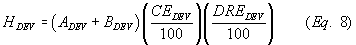
Where:
HDEV = Mass of organic HAP emission reduction achieved during a period of deviation for the controlled coating operation, kg.
ADEV = Total mass of organic HAP in the coatings used in the controlled coating operation during the period of deviation, kg, as calculated in Equation 8A of this section.
BDEV = Total mass of organic HAP in the thinners used in the controlled coating operation during the period of deviation, kg, as calculated in Equation 8B of this section.
CEDEV = Capture efficiency of the emission capture system vented to the add-on control device, approved for the period of deviation, percent.
DREDEV = Organic HAP destruction or removal efficiency of the add-on control device approved for the period of deviation, percent.
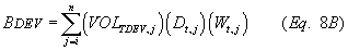
(4) Calculate the total mass of organic HAP in the coatings used in the controlled coating operation during the period of deviation using equation 8A of this section:
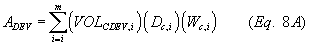
Where:
ADEV = Total mass of organic HAP in the coatings used in the controlled coating operation during the period of deviation, kg.
VOLCDEV, i = total volume of coating, i, used in the controlled coating operation during the period of deviation, liters.
Dc, i = Density of coating, i, kg per liter.
Wc, i = Mass fraction of organic HAP in coating, i, kg per kg.
m = Number of different coatings used.
(5) Calculate the total mass of organic HAP in the thinners used in the controlled coating operation during the period of deviation using equation 8B of this section:
Where:
BDEV = Total mass of organic HAP in the thinners used in the controlled coating operation during the period of deviation, kg.
VOLTDEV, j = Total volume of thinner, j, used in the controlled coating operation during the period of deviation, liters.
Dt, j = Density of thinner, j, kg per liter.
Wt, j = Mass fraction of organic HAP in thinner, j, kg per kg.
n = Number of different thinners used.
[69 FR 22623, Apr. 26, 2004, as amended at 72 FR 20233, Apr. 24, 2007; 85 FR 41129, July 8, 2020; 86 FR 66040, Nov. 19, 2021]
(a) To demonstrate continuous compliance with the applicable emission limit in §63.3090(a) or §63.3091(a), the organic HAP emission rate for each compliance period, determined according to the procedures in §63.3161, must be equal to or less than the applicable emission limit in §63.3090(a) or §63.3091(a). A compliance period consists of 1 month. Each month after the end of the initial compliance period described in §63.3160 is a compliance period consisting of that month. You must perform the calculations in §63.3161 on a monthly basis.
(b) If the organic HAP emission rate for any 1 month compliance period exceeded the applicable emission limit in §63.3090(a) or §63.3091(a), this is a deviation from the emission limitation for that compliance period and must be reported as specified in §§63.3110(c)(6) and 63.3120(a)(6).
(c) You must demonstrate continuous compliance with each operating limit required by §63.3093 that applies to you, as specified in table 1 to this subpart, and you must conduct performance tests as specified in paragraph (c)(3) of this section.
(1) If an operating parameter is out of the allowed range specified in Table 1 to this subpart, this is a deviation from the operating limit that must be reported as specified in §§63.3110(c)(6) and 63.3120(a)(6).
(2) If an operating parameter deviates from the operating limit specified in Table 1 to this subpart, then you must assume that the emission capture system and add-on control device were achieving zero efficiency during the time period of the deviation except as provided in §63.3161(p).
(3) Except for solvent recovery systems for which you conduct liquid-liquid material balances according to §63.3161(k) for controlled coating operations, you must conduct periodic performance tests of add-on controls and establish the operating limits required by §63.3093 within 5 years following the previous performance test. You must conduct the first periodic performance test before July 8, 2023, unless you are already required to complete periodic performance tests as a requirement of renewing your facility's operating permit under 40 CFR part 70 or 40 CFR part 71 and have conducted a performance test on or after July 8, 2022. Thereafter you must conduct a performance test no later than 5 years following the previous performance test. Operating limits must be confirmed or reestablished during each performance test. For any control device for which you are using the catalytic oxidizer control option at §63.3167(b) and following the catalyst maintenance procedures in §63.3167(b)(6), you are not required to conduct periodic control device performance testing as specified by this paragraph. For any control device for which instruments are used to continuously measure organic compound emissions, you are not required to conduct periodic control device performance testing as specified by this paragraph. The requirements of this paragraph do not apply to measuring emission capture system efficiency.
(d) You must meet the requirements for bypass lines in §63.3168(b) for control devices other than solvent recovery systems for which you conduct liquid-liquid material balances. If any bypass line is opened and emissions are diverted to the atmosphere when the coating operation is running, this is a deviation that must be reported as specified in §§63.3110(c)(6) and 63.3120(a)(6). For the purposes of completing the compliance calculations specified in §63.3161(k), you must assume that the emission capture system and add-on control device were achieving zero efficiency during the time period of the deviation.
(e) You must demonstrate continuous compliance with the work practice standards in §63.3094. If you did not develop a work practice plan, if you did not implement the plan, or if you did not keep the records required by §63.3130(n), this is a deviation from the work practice standards that must be reported as specified in §§63.3110(c)(6) and 63.3120(a)(6).
(f) If there were no deviations from the emission limitations, submit a statement as part of the semiannual compliance report that you were in compliance with the emission limitations during the reporting period because the organic HAP emission rate for each compliance period was less than or equal to the applicable emission limit in §63.3090(a) or §63.3091(a), §63.3090(b) or §63.3091(b), or §63.3092(a) or §63.3092(b), you achieved the operating limits required by §63.3093, and you achieved the work practice standards required by §63.3094 during each compliance period.
(g) [Reserved]
(h) Before January 5, 2021, consistent with §§63.6(e) and 63.7(e)(1), deviations that occur during a period of SSM of the emission capture system, add-on control device, or coating operation that may affect emission capture or control device efficiency are not violations if you demonstrate to the Administrator's satisfaction that you were operating in accordance with §63.6(e)(1). The Administrator will determine whether deviations that occur during a period you identify as a SSM are violations according to the provisions in §63.6(e). On and after January 5, 2021, the provisions of this paragraph no longer apply.
(i) [Reserved]
(j) You must maintain records as specified in §§63.3130 and 63.3131.
[69 FR 22623, Apr. 26, 2004, as amended at 71 FR 20464, Apr. 20, 2006; 85 FR 41130, July 8, 2020]
(a) You must conduct each applicable performance test required by §§63.3160, 63.3163, and 63.3171 according to the requirements in §63.7(e)(1) and under the conditions in this section unless you obtain a waiver of the performance test according to the provisions in §63.7(h).
(1) Representative coating operation operating conditions. You must conduct the performance test under representative operating conditions for the coating operation. Before January 5, 2021, operations during periods of SSM, and during periods of nonoperation do not constitute representative conditions. You must record the process information that is necessary to document operating conditions during the test and explain why the conditions represent normal operation. On and after January 5, 2021, operations during periods of startup, shutdown, or nonoperation do not constitute representative conditions for purposes of conducting a performance test. The owner or operator may not conduct performance tests during periods of malfunction. You must record the process information that is necessary to document operating conditions during the test and explain why the conditions represent normal operation. Upon request, you must make available to the Administrator such records as may be necessary to determine the conditions of performance tests.
(2) Representative emission capture system and add-on control device operating conditions. You must conduct the performance test when the emission capture system and add-on control device are operating at a representative flow rate, and the add-on control device is operating at a representative inlet concentration. You must record information that is necessary to document emission capture system and add-on control device operating conditions during the test and explain why the conditions represent normal operation.
(b) You must conduct each performance test of an emission capture system according to the requirements in §63.3165. You must conduct each performance test of an add-on control device according to the requirements in §63.3166.
[85 FR 41130, July 8, 2020]
You must use the procedures and test methods in this section to determine capture efficiency as part of the performance test required by §§63.3160 and 63.3163. For purposes of this subpart, a spray booth air seal is not considered a natural draft opening in a PTE or a temporary total enclosure provided you demonstrate that the direction of air movement across the interface between the spray booth air seal and the spray booth is into the spray booth. For purposes of this subpart, a bake oven air seal is not considered a natural draft opening in a PTE or a temporary total enclosure provided you demonstrate that the direction of air movement across the interface between the bake oven air seal and the bake oven is into the bake oven. You may use lightweight strips of fabric or paper, or smoke tubes to make such demonstrations as part of showing that your capture system is a PTE or conducting a capture efficiency test using a temporary total enclosure. You cannot count air flowing from a spray booth air seal into a spray booth as air flowing through a natural draft opening into a PTE or into a temporary total enclosure unless you elect to treat that spray booth air seal as a natural draft opening. You cannot count air flowing from a bake oven air seal into a bake oven as air flowing through a natural draft opening into a PTE or into a temporary total enclosure unless you elect to treat that bake oven air seal as a natural draft opening.
(a) Assuming 100 percent capture efficiency. You may assume the capture system efficiency is 100 percent if both of the conditions in paragraphs (a)(1) and (2) of this section are met:
(1) The capture system meets the criteria in Method 204 of appendix M to 40 CFR part 51 for a PTE and directs all the exhaust gases from the enclosure to an add-on control device.
(2) All coatings and thinners used in the coating operation are applied within the capture system, and coating solvent flash-off and coating curing and drying occurs within the capture system. For example, this criterion is not met if parts enter the open shop environment when being moved between a spray booth and a curing oven.
(b) Measuring capture efficiency. If the capture system does not meet both of the criteria in paragraphs (a)(1) and (2) of this section, then you must use one of the five procedures described in paragraphs (c) through (g) of this section to measure capture efficiency. The capture efficiency measurements use TVH capture efficiency as a surrogate for organic HAP capture efficiency. For the protocols in paragraphs (c) and (d) of this section, the capture efficiency measurement must consist of three test runs. Each test run must be at least 3 hours duration or the length of a production run, whichever is longer, up to 8 hours. For the purposes of this test, a production run means the time required for a single part to go from the beginning to the end of production, which includes surface preparation activities and drying or curing time.
(c) Liquid-to-uncaptured-gas protocol using a temporary total enclosure or building enclosure. The liquid-to-uncaptured-gas protocol compares the mass of liquid TVH in materials used in the coating operation to the mass of TVH emissions not captured by the emission capture system. Use a temporary total enclosure or a building enclosure and the procedures in paragraphs (c)(1) through (6) of this section to measure emission capture system efficiency using the liquid-to-uncaptured-gas protocol.
(1) Either use a building enclosure or construct an enclosure around the coating operation where coatings and thinners are applied, and all areas where emissions from these applied coatings and thinners subsequently occur, such as flash-off, curing, and drying areas. The areas of the coating operation where capture devices collect emissions for routing to an add-on control device, such as the entrance and exit areas of an oven or spray booth, must also be inside the enclosure. The enclosure must meet the applicable definition of a temporary total enclosure or building enclosure in Method 204 of appendix M to 40 CFR part 51.
(2) Use Method 204A or F of appendix M to 40 CFR part 51 to determine the mass fraction of TVH liquid input from each coating and thinner used in the coating operation during each capture efficiency test run. To make the determination, substitute TVH for each occurrence of the term volatile organic compounds (VOC) in the methods.
(3) Use Equation 1 of this section to calculate the total mass of TVH liquid input from all the coatings and thinners used in the coating operation during each capture efficiency test run.
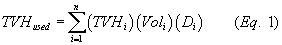
Where:
TVHi = Mass fraction of TVH in coating or thinner, i, used in the coating operation during the capture efficiency test run, kg TVH per kg material.
Voli = Total volume of coating or thinner, i, used in the coating operation during the capture efficiency test run, liters.
Di = Density of coating or thinner, i, kg material per liter material.
n = Number of different coatings and thinners used in the coating operation during the capture efficiency test run.
(4) Use Method 204D or E of appendix M to 40 CFR part 51 to measure the total mass, kg, of TVH emissions that are not captured by the emission capture system; they are measured as they exit the temporary total enclosure or building enclosure during each capture efficiency test run. To make the measurement, substitute TVH for each occurrence of the term VOC in the methods.
(i) Use Method 204D if the enclosure is a temporary total enclosure.
(ii) Use Method 204E if the enclosure is a building enclosure. During the capture efficiency measurement, all organic compound emitting operations inside the building enclosure, other than the coating operation for which capture efficiency is being determined, must be shut down, but all fans and blowers must be operating normally.
(5) For each capture efficiency test run, determine the percent capture efficiency of the emission capture system using Equation 2 of this section:
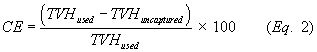
Where:
CE = Capture efficiency of the emission capture system vented to the add-on control device, percent.
TVH used = Total mass of TVH liquid input used in the coating operation during the capture efficiency test run, kg.
TVH uncaptured = Total mass of TVH that is not captured by the emission capture system and that exits from the temporary total enclosure or building enclosure during the capture efficiency test run, kg.
(6) Determine the capture efficiency of the emission capture system as the average of the capture efficiencies measured in the three test runs.
(d) Gas-to-gas protocol using a temporary total enclosure or a building enclosure. The gas-to-gas protocol compares the mass of TVH emissions captured by the emission capture system to the mass of TVH emissions not captured. Use a temporary total enclosure or a building enclosure and the procedures in paragraphs (d)(1) through (5) of this section to measure emission capture system efficiency using the gas-to-gas protocol.
(1) Either use a building enclosure or construct an enclosure around the coating operation where coatings and thinners are applied, and all areas where emissions from these applied coatings and thinners subsequently occur, such as flash-off, curing, and drying areas. The areas of the coating operation where capture devices collect emissions generated by the coating operation for routing to an add-on control device, such as the entrance and exit areas of an oven or a spray booth, must also be inside the enclosure. The enclosure must meet the applicable definition of a temporary total enclosure or building enclosure in Method 204 of appendix M to 40 CFR part 51.
(2) Use Method 204B or C of appendix M to 40 CFR part 51 to measure the total mass, kg, of TVH emissions captured by the emission capture system during each capture efficiency test run as measured at the inlet to the add-on control device. To make the measurement, substitute TVH for each occurrence of the term VOC in the methods.
(i) The sampling points for the Method 204B or C measurement must be upstream from the add-on control device and must represent total emissions routed from the capture system and entering the add-on control device.
(ii) If multiple emission streams from the capture system enter the add-on control device without a single common duct, then the emissions entering the add-on control device must be simultaneously or sequentially measured in each duct, and the total emissions entering the add-on control device must be determined.
(3) Use Method 204D or E of appendix M to 40 CFR part 51 to measure the total mass, kg, of TVH emissions that are not captured by the emission capture system; they are measured as they exit the temporary total enclosure or building enclosure during each capture efficiency test run. To make the measurement, substitute TVH for each occurrence of the term VOC in the methods.
(i) Use Method 204D if the enclosure is a temporary total enclosure.
(ii) Use Method 204E if the enclosure is a building enclosure. During the capture efficiency measurement, all organic compound emitting operations inside the building enclosure, other than the coating operation for which capture efficiency is being determined, must be shut down, but all fans and blowers must be operating normally.
(4) For each capture efficiency test run, determine the percent capture efficiency of the emission capture system using Equation 3 of this section:
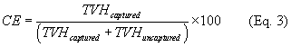
Where:
CE = Capture efficiency of the emission capture system vented to the add-on control device, percent.
TVHcaptured = Total mass of TVH captured by the emission capture system as measured at the inlet to the add-on control device during the emission capture efficiency test run, kg.
TVHuncaptured = Total mass of TVH that is not captured by the emission capture system and that exits from the temporary total enclosure or building enclosure during the capture efficiency test run, kg.
(5) Determine the capture efficiency of the emission capture system as the average of the capture efficiencies measured in the three test runs.
(e) Panel testing to determine the capture efficiency of flash-off or bake oven emissions. You may conduct panel testing to determine the capture efficiency of flash-off or bake oven emissions using ASTM Method D5087-02, “Standard Test Method for Determining Amount of Volatile Organic Compound (VOC) Released from Solventborne Automotive Coatings and Available for Removal in a VOC Control Device (Abatement)” (incorporated by reference, see §63.14), ASTM Method D6266-00a (2017), “Test Method for Determining the Amount of Volatile Organic Compound (VOC) Released from Waterborne Automotive Coatings and Available for Removal in a VOC Control Device (Abatement)” (incorporated by reference, see §63.14), or the guidelines presented in “Protocol for Determining the Daily Volatile Organic Compound Emission Rate of Automobile and Light-Duty Truck Primer-Surfacer and Topcoat” EPA-453/R-08-002 (incorporated by reference, see §63.14). You may conduct panel testing on representative coatings as described in “Protocol for Determining the Daily Volatile Organic Compound Emission Rate of Automobile and Light-Duty Truck Primer-Surfacer and Topcoat” EPA-453/R-08-002 (incorporated by reference, see §63.14).

Where:
CEi = Capture efficiency for coating, i, or for the group of coatings, including coating, i, for the flash-off area or bake oven for which the panel test is conducted, percent.
Pv,i = Panel test result for coating, i, or for the coating representing coating, i, in the panel test, kg of VOC per liter of coating solids deposited.
Vsdep,i = Volume of coating solids deposited per volume of coating used for coating, i, or composite volume of coating solids deposited per volume of coating used for the group of coatings including coating, i, in the spray booth(s) preceding the flash-off area or bake oven for which the panel test is conducted, liter of coating solids deposited per liter of coating used, from Equation 5 of this section.
VOCi = Mass of VOC per volume of coating for coating, i, or composite mass of VOC per volume of coating for the group of coatings including coating, i, kg per liter, from Equation 6 of this section.
(1) Calculate the volume of coating solids deposited per volume of coating used for coating, i, or the composite volume of coating solids deposited per volume of coating used for the group of coatings including coating, i, used during the month in the spray booth(s) preceding the flash-off area or bake oven for which the panel test is conducted using Equation 5 of this section:
Where:
Vsdep, i = Volume of coating solids deposited per volume of coating used for coating, i, or composite volume of coating solids deposited per volume of coating used for the group of coatings including coating, i, in the spray booth(s) preceding the flash-off area or bake oven for which the panel test is conducted, liter of coating solids deposited per liter of coating used.
Vs, i = Volume fraction of coating solids for coating, i, or average volume fraction of coating solids for the group of coatings including coating, i, liter coating solids per liter coating, determined according to §63.3161(f).
TEc, i = Transfer efficiency of coating, i, or average transfer efficiency for the group of coatings including coating, i, in the spray booth(s) for the flash-off area or bake oven for which the panel test is conducted determined according to §63.3161(g), expressed as a decimal, for example 60 percent must be expressed as 0.60. (Transfer efficiency also may be determined by testing representative coatings. The same coating groupings may be appropriate for both transfer efficiency testing and panel testing. In this case, all of the coatings in a panel test grouping would have the same transfer efficiency.)
(2) Calculate the mass of VOC per volume of coating for coating, i, or the composite mass of VOC per volume of coating for the group of coatings including coating, i, used during the month in the spray booth(s) preceding the flash-off area or bake oven for which the panel test is conducted, kg, using Equation 6 of this section:
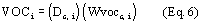
Where:
VOCi = Mass of VOC per volume of coating for coating, i, or composite mass of VOC per volume of coating for the group of coatings including coating, i, used during the month in the spray booth(s) preceding the flash-off area or bake oven for which the panel test is conducted, kg VOC per liter coating.
Dc,i = Density of coating, i, or average density of the group of coatings, including coating, i, kg coating per liter coating, density determined according to §63.3151(b).
Wvocc,i = Mass fraction of VOC in coating, i, or average mass fraction of VOC for the group of coatings, including coating, i, kg VOC per kg coating, determined by EPA Method 24 (appendix A-7 to 40 CFR part 60) or the guidelines for combining analytical VOC content and formulation solvent content presented in Section 9 of “Protocol for Determining the Daily Volatile Organic Compound Emission Rate of Automobile and Light-Duty Truck Primer-Surfacer and Topcoat, EPA-453/R-08-002” (incorporated by reference, see §63.14).
(3) As an alternative, you may choose to express the results of your panel tests in units of mass of VOC per mass of coating solids deposited and convert such results to a percent using Equation 7 of this section. If you panel test representative coatings, then you may convert the panel test result for each representative coating either to a unique percent capture efficiency for each coating grouped with that representative coating by using coating specific values for the mass of coating solids deposited per mass of coating used, mass fraction VOC, transfer efficiency, and mass fraction solids in Equations 7 and 8 of this section; or to a composite percent capture efficiency for the group of coatings by using composite values for the group of coatings for the mass of coating solids deposited per mass of coating used and average values for the mass of VOC per volume of coating, average values for the group of coatings for mass fraction VOC, transfer efficiency, and mass fraction solids in Equations 7 and 8 of this section. If you panel test each coating, then you must convert the panel test result for each coating to a unique percent capture efficiency for that coating by using coating specific values for the mass of coating solids deposited per mass of coating used, mass fraction VOC, transfer efficiency, and mass fraction solids in Equations 7 and 8 of this section. Panel test results expressed in units of mass of VOC per mass of coating solids deposited must be converted to percent capture efficiency using Equation 7 of this section:

Where:
CEi = Capture efficiency for coating, i, or for the group of coatings including coating, i, for the flash-off area or bake oven for which the panel test is conducted, percent.
Pm,i = Panel test result for coating, i, or for the coating representing coating, i, in the panel test, kg of VOC per kg of coating solids deposited.
Wsdep,i = Mass of coating solids deposited per mass of coating used for coating, i, or composite mass of coating solids deposited per mass of coating used for the group of coatings, including coating, i, in the spray booth(s) preceding the flash-off area or bake oven for which the panel test is conducted, kg of solids deposited per kg of coating used, from Equation 8 of this section.
Wvocc,i = Mass fraction of VOC in coating, i, or average mass fraction of VOC for the group of coatings, including coating, i, kg VOC per kg coating, determined by EPA Method 24 (appendix A-7 to 40 CFR part 60) or the guidelines for combining analytical VOC content and formulation solvent content presented in Section 9 of “Protocol for Determining the Daily Volatile Organic Compound Emission Rate of Automobile and Light-Duty Truck Primer-Surfacer and Topcoat, EPA-453/R-08-002” (incorporated by reference, see §63.14).
(4) Calculate the mass of coating solids deposited per mass of coating used for each coating or the composite mass of coating solids deposited per mass of coating used for each group of coatings used during the month in the spray booth(s) preceding the flash-off area or bake oven for which the panel test is conducted using Equation 8 of this section:
Where:
Wsdep, i = Mass of coating solids deposited per mass of coating used for coating, i, or composite mass of coating solids deposited per mass of coating used for the group of coatings including coating, i, in the spray booth(s) preceding the flash-off area or bake oven for which the panel test is conducted, kg coating solids deposited per kg coating used.
Ws, i = Mass fraction of coating solids for coating, i, or average mass fraction of coating solids for the group of coatings including coating, i, kg coating solids per kg coating, determined by EPA Method 24 (appendix A-7 to 40 CFR part 60) or the guidelines for combining analytical VOC content and formulation solvent content presented in “Protocol for Determining the Daily Volatile Organic Compound Emission Rate of Automobile and Light-Duty Truck Primer-Surfacer and Topcoat, EPA-453/R-08-002” (incorporated by reference, see §63.14).
TEc, i = Transfer efficiency of coating, i, or average transfer efficiency for the group of coatings including coating, i, in the spray booth(s) for the flash-off area or bake oven for which the panel test is conducted determined according to §63.3161(g), expressed as a decimal, for example 60 percent must be expressed as 0.60. (Transfer efficiency also may be determined by testing representative coatings. The same coating groupings may be appropriate used for both transfer efficiency testing and panel testing. In this case, all of the coatings in a panel test grouping would have the same transfer efficiency.)
(f) Alternative capture efficiency procedure. As an alternative to the procedures specified in paragraphs (c) through (e) and (g) of this section, you may determine capture efficiency using any other capture efficiency protocol and test methods that satisfy the criteria of either the DQO or LCL approach as described in appendix A to subpart KK of this part.
(g) Panel testing to determine the capture efficiency of spray booth emissions from solvent-borne coatings. You may conduct panel testing to determine the capture efficiency of spray booth emissions from solvent-borne coatings using the procedure in appendix A to this subpart.
[69 FR 22623, Apr. 26, 2004, as amended at 72 FR 20234, Apr. 24, 2007; 85 FR 41131, July 8, 2020; 86 FR 66040, Nov. 19, 2021]
You must use the procedures and test methods in this section to determine the add-on control device emission destruction or removal efficiency as part of the performance test required by §63.3160, §63.3163, or §63.3171. You must conduct three test runs as specified in §63.7(e)(3), and each test run must last at least 1 hour.
(a) For all types of add-on control devices, use the test methods specified in paragraphs (a)(1) through (5) of this section.
(1) Use EPA Method 1 or 1A of appendix A-1 to 40 CFR part 60, as appropriate, to select sampling sites and velocity traverse points.
(2) Use EPA Method 2, 2A, 2C, 2D, or 2F of appendix A-1, or 2G of appendix A-2 to 40 CFR part 60, as appropriate, to measure gas volumetric flow rate.
(3) Use EPA Method 3, 3A, or 3B of appendix A-2 to 40 CFR part 60, as appropriate, for gas analysis to determine dry molecular weight. The ANSI/ASME PTC 19.10-1981 (incorporated by reference, see §63.14), may be used as an alternative to EPA Method 3B.
(4) Use EPA Method 4 of appendix A-3 to 40 CFR part 60 to determine stack gas moisture.
(5) Methods for determining gas volumetric flow rate, dry molecular weight, and stack gas moisture must be performed, as applicable, during each test run.
(b) Measure total gaseous organic mass emissions as carbon at the inlet and outlet of the add-on control device simultaneously, using either EPA Method 25 or 25A of appendix A-7 to 40 CFR part 60, as specified in paragraphs (b)(1) through (4) of this section. You must use the same method for both the inlet and outlet measurements.
(1) Use Method 25 if the add-on control device is an oxidizer and you expect the total gaseous organic concentration as carbon to be more than 50 parts per million by volume (ppmv) at the control device outlet.
(2) Use Method 25A if the add-on control device is an oxidizer and you expect the total gaseous organic concentration as carbon to be 50 ppmv or less at the control device outlet.
(3) Use Method 25A if the add-control device is not an oxidizer.
(4) You may use EPA Method 18 of appendix A-6 to 40 CFR part 60 to subtract methane emissions from measured total gaseous organic mass emissions as carbon.
(c) If two or more add-on control devices are used for the same emission stream, then you must measure emissions at the outlet of each device. For example, if one add-on control device is a concentrator with an outlet for the high-volume, dilute stream that has been treated by the concentrator, and a second add-on control device is an oxidizer with an outlet for the low-volume, concentrated stream that is treated with the oxidizer, you must measure emissions at the outlet of the oxidizer and the high volume dilute stream outlet of the concentrator.
(d) For each test run, determine the total gaseous organic emissions mass flow rates for the inlet and the outlet of the add-on control device, using Equation 1 of this section. If there is more than one inlet or outlet to the add-on control device, you must calculate the total gaseous organic mass flow rate using Equation 1 of this section for each inlet and each outlet and then total all of the inlet emissions and total all of the outlet emissions.
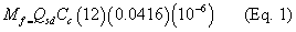
Where:
Mf = Total gaseous organic emissions mass flow rate, kg per hour (kg/h).
Cc = Concentration of organic compounds as carbon in the vent gas, as determined by Method 25 or Method 25A, ppmv, dry basis.
Qsd = Volumetric flow rate of gases entering or exiting the add-on control device, as determined by Method 2, 2A, 2C, 2D, 2F, or 2G, dry standard cubic meters per hour (dscm/h).
0.0416 = Conversion factor for molar volume, kg-moles per cubic meter (mol/m 3) (@ 293 Kelvin (K) and 760 millimeters of mercury (mmHg)).
(e) For each test run, determine the add-on control device organic emissions destruction or removal efficiency using Equation 2 of this section:
Where:
DRE = Organic emissions destruction or removal efficiency of the add-on control device, percent.
Mfi = Total gaseous organic emissions mass flow rate at the inlet(s) to the add-on control device, using Equation 1 of this section, kg/h.
Mfo = Total gaseous organic emissions mass flow rate at the outlet(s) of the add-on control device, using Equation 1 of this section, kg/h.
(f) Determine the emission destruction or removal efficiency of the add-on control device as the average of the efficiencies determined in the three test runs and calculated in Equation 2 of this section.
[85 FR 41131, July 8, 2020]
During the performance tests required by §§63.3160, 63.3163, and 63.3171 (and described in §§63.3164 and 63.3166), you must establish the operating limits required by §63.3093 according to this section, unless you have received approval for alternative monitoring and operating limits under §63.8(f) as specified in §63.3093.
(a) Thermal oxidizers. If your add-on control device is a thermal oxidizer, establish the operating limit according to paragraphs (a)(1) through (3) of this section.
(1) During the performance test, you must monitor and record the combustion temperature at least once every 15 minutes during each of the three test runs. You must monitor the temperature in the firebox of the thermal oxidizer or immediately downstream of the firebox before any substantial heat exchange occurs.
(2) Use all valid data collected during the performance test to calculate and record the average combustion temperature maintained during the performance test. This average combustion temperature is the minimum 3-hour average operating limit for your thermal oxidizer.
(3) As an alternative, if the latest operating permit issued before April 26, 2007, for the thermal oxidizer at your facility contains recordkeeping and reporting requirements for the combustion temperature that are consistent with the requirements for thermal oxidizers in 40 CFR 60.395(c), then you may set the minimum operating limit for the combustion temperature for each such thermal oxidizer at your affected source at 28 degrees Celsius (50 degrees Fahrenheit) below the average combustion temperature during the performance test of that thermal oxidizer. If you do not have an operating permit for the thermal oxidizer at your facility and the latest construction permit issued before April 26, 2007, for the thermal oxidizer at your facility contains recordkeeping and reporting requirements for the combustion temperature that are consistent with the requirements for thermal oxidizers in 40 CFR 60.395(c), then you may set the minimum operating limit for the combustion temperature for each such thermal oxidizer at your affected source at 28 degrees Celsius (50 degrees Fahrenheit) below the average combustion temperature during the performance test of that thermal oxidizer. If you use 28 degrees Celsius (50 degrees Fahrenheit) below the combustion temperature maintained during the performance test as the minimum operating limit for a thermal oxidizer, then you must keep the combustion temperature set point on that thermal oxidizer no lower than 14 degrees Celsius (25 degrees Fahrenheit) below the lower of that set point during the performance test for that thermal oxidizer and the average combustion temperature maintained during the performance test for that thermal oxidizer.
(b) Catalytic oxidizers. If your add-on control device is a catalytic oxidizer, establish the operating limits according to either paragraphs (b)(1) through (3) or paragraphs (b)(4) through (6) of this section.
(1) During the performance test, you must monitor and record the temperature just before the catalyst bed and the temperature difference across the catalyst bed at least once every 15 minutes during each of the three test runs.
(2) Use all valid data collected during the performance test to calculate and record the average temperature just before the catalyst bed and the average temperature difference across the catalyst bed maintained during the performance test. The minimum 3-hour average operating limits for your catalytic oxidizer are the average temperature just before the catalyst bed maintained during the performance test of that catalytic oxidizer and 80 percent of the average temperature difference across the catalyst bed maintained during the performance test of that catalytic oxidizer, except during periods of low production, the latter minimum operating limit is to maintain a positive temperature gradient across the catalyst bed. A low production period is when production is less than 80 percent of production rate during the performance test of that catalytic oxidizer.
(3) As an alternative, if the latest operating permit issued before April 26, 2007, for the catalytic oxidizer at your facility contains recordkeeping and reporting requirements for the temperature before the catalyst bed that are consistent with the requirements for catalytic oxidizers in 40 CFR 60.395(c), then you may set the minimum operating limits for each such catalytic oxidizer at your affected source at 28 degrees Celsius (50 degrees Fahrenheit) below the average temperature just before the catalyst bed maintained during the performance test for that catalytic oxidizer and 80 percent of the average temperature difference across the catalyst bed maintained during the performance test for that catalytic oxidizer, except during periods of low production the latter minimum operating limit is to maintain a positive temperature gradient across the catalyst bed. If you do not have an operating permit for the catalytic oxidizer at your facility and the latest construction permit issued before April 26, 2007, for the catalytic oxidizer at your facility contains recordkeeping and reporting requirements for the temperature before the catalyst bed that are consistent with the requirements for catalytic oxidizers in 40 CFR 60.395(c), then you may set the minimum operating limits for each such catalytic oxidizer at your affected source at 28 degrees Celsius (50 degrees Fahrenheit) below the average temperature just before the catalyst bed maintained during the performance test for that catalytic oxidizer and 80 percent of the average temperature difference across the catalyst bed maintained during the performance test for that catalytic oxidizer, except during periods of low production the latter minimum operating limit is to maintain a positive temperature gradient across the catalyst bed. A low production period is when production is less than 80 percent of production rate during the performance test. If you use 28 degrees Celsius (50 degrees Fahrenheit) below the average temperature just before the catalyst bed maintained during the performance test as the minimum operating limits for a catalytic oxidizer, then you must keep the set point for the temperature just before the catalyst bed on that catalytic oxidizer no lower than 14 degrees Celsius (25 degrees Fahrenheit) below the lower of that set point during the performance test for that catalytic oxidizer and the average temperature just before the catalyst bed maintained during the performance test for that catalytic oxidizer.
(4) As an alternative to monitoring the temperature difference across the catalyst bed, you may monitor the temperature at the inlet to the catalyst bed and implement a site-specific inspection and maintenance plan for your catalytic oxidizer as specified in paragraph (b)(6) of this section. During the performance test, you must monitor and record the temperature just before the catalyst bed at least once every 15 minutes during each of the three test runs. Use all valid data collected during the performance test to calculate and record the average temperature just before the catalyst bed during the performance test. This is the minimum operating limit for your catalytic oxidizer.
(5) If the latest operating permit issued before April 26, 2007, for the catalytic oxidizer at your facility contains recordkeeping and reporting requirements for the temperature before the catalyst bed that are consistent with the requirements for catalytic oxidizers in 40 CFR 60.395(c), then you may set the minimum operating limit for each such catalytic oxidizer at your affected source at 28 degrees Celsius (50 degrees Fahrenheit) below the average temperature just before the catalyst bed maintained during the performance test for that catalytic oxidizer. If you do not have an operating permit for the catalytic oxidizer at your facility and the latest construction permit issued before April 26, 2007, for the catalytic oxidizer at your facility contains recordkeeping and reporting requirements for the temperature before the catalyst bed that are consistent with the requirements for catalytic oxidizers in 40 CFR 60.395(c), then you may set the minimum operating limit for each such catalytic oxidizer at your affected source at 28 degrees Celsius (50 degrees Fahrenheit) below the average temperature just before the catalyst bed maintained during the performance test for that catalytic oxidizer. If you use 28 degrees Celsius (50 degrees Fahrenheit) below the average temperature just before the catalyst bed maintained during the performance test as the minimum operating limit for a catalytic oxidizer, then you must keep the set point for the temperature just before the catalyst bed on that catalytic oxidizer no lower than 14 degrees Celsius (25 degrees Fahrenheit) below the lower of that set point during the performance test for that catalytic oxidizer and the average temperature just before the catalyst bed maintained during the performance test for that catalytic oxidizer.
(6) You must develop and implement an inspection and maintenance plan for your catalytic oxidizer(s) for which you elect to monitor according to paragraph (b)(4) or (b)(5) of this section. The plan must address, at a minimum, the elements specified in paragraphs (b)(6)(i) through (iii) of this section.
(i) Annual sampling and analysis of the catalyst activity (i.e., conversion efficiency) following the manufacturer's or catalyst supplier's recommended procedures. If problems are found during the catalyst activity test, you must replace the catalyst bed or take other corrective action consistent with the manufacturer's recommendations.
(ii) Monthly external inspection of the catalytic oxidizer system, including the burner assembly and fuel supply lines for problems and, as necessary, adjust the equipment to assure proper air-to-fuel mixtures.
(iii) Annual internal inspection of the catalyst bed to check for channeling, abrasion, and settling. If problems are found during the annual internal inspection of the catalyst, you must replace the catalyst bed or take other corrective action consistent with the manufacturer's recommendations. If the catalyst bed is replaced and is not of like or better kind and quality as the old catalyst, then you must conduct a new performance test to determine destruction efficiency according to §63.3166. If a catalyst bed is replaced and the replacement catalyst is of like or better kind and quality as the old catalyst, then a new performance test to determine destruction efficiency is not required and you may continue to use the previously established operating limits for that catalytic oxidizer.
(c) Regenerative carbon adsorbers. If your add-on control device is a regenerative carbon adsorber, establish the operating limits according to paragraphs (c)(1) and (2) of this section.
(1) You must monitor and record the total regeneration desorbing gas (e.g., steam or nitrogen) mass flow for each regeneration cycle and the carbon bed temperature after each carbon bed regeneration and cooling cycle for the regeneration cycle either immediately preceding or immediately following the performance test.
(2) The operating limits for your carbon adsorber are the minimum total desorbing gas mass flow recorded during the regeneration cycle and the maximum carbon bed temperature recorded after the cooling cycle.
(d) Condensers. If your add-on control device is a condenser, establish the operating limits according to paragraphs (d)(1) and (2) of this section.
(1) During the performance test, you must monitor and record the condenser outlet (product side) gas temperature at least once every 15 minutes during each of the three test runs.
(2) Use all valid data collected during the performance test to calculate and record the average condenser outlet (product side) gas temperature maintained during the performance test. This average condenser outlet gas temperature is the maximum 3-hour average operating limit for your condenser.
(e) Concentrators. If your add-on control device includes a concentrator, you must establish operating limits for the concentrator according to paragraphs (e)(1) and (2)of this section.
(1) During the performance test, you must monitor and record the desorption gas inlet temperature at least once every 15 minutes during each of the three runs of the performance test.
(2) Use all valid data collected during the performance test to calculate and record the average desorption gas inlet temperature. The minimum operating limit for the concentrator is 8 degrees Celsius (15 degrees Fahrenheit) below the average desorption gas inlet temperature maintained during the performance test for that concentrator. You must keep the set point for the desorption gas inlet temperature no lower than 6 degrees Celsius (10 degrees Fahrenheit) below the lower of that set point during the performance test for that concentrator and the average desorption gas inlet temperature maintained during the performance test for that concentrator.
(f) Emission capture systems. For each capture device that is not part of a PTE that meets the criteria of §63.3165(a) and that is not capturing emissions from a downdraft spray booth or from a flash-off area or bake oven associated with a downdraft spray booth, establish an operating limit for either the gas volumetric flow rate or duct static pressure, as specified in paragraphs (f)(1) and (2) of this section. The operating limit for a PTE is specified in Table 1 to this subpart.
(1) During the capture efficiency determination required by §§63.3160 and 63.3163 and described in §§63.3164 and 63.3165, you must monitor and record either the gas volumetric flow rate or the duct static pressure for each separate capture device in your emission capture system at least once every 15 minutes during each of the three test runs at a point in the duct between the capture device and the add-on control device inlet.
(2) Calculate and record the average gas volumetric flow rate or duct static pressure for the three test runs for each capture device, using all valid data. This average gas volumetric flow rate or duct static pressure is the minimum operating limit for that specific capture device.
[69 FR 22623, Apr. 26, 2004, as amended at 72 FR 20235, Apr. 24, 2007; 85 FR 41132, July 8, 2020]
(a) General. You must install, operate, and maintain each CPMS specified in paragraphs (c), (e), (f), and (g) of this section according to paragraphs (a)(1) through (6) of this section. You must install, operate, and maintain each CPMS specified in paragraphs (b) and (d) of this section according to paragraphs (a)(3) through (5) of this section.
(1) The CPMS must complete a minimum of one cycle of operation for each successive 15-minute period. You must have a minimum of four equally-spaced successive cycles of CPMS operation in 1 hour.
(2) You must determine the average of all recorded readings for each successive 3-hour period of the emission capture system and add-on control device operation.
(3) You must record the results of each inspection, calibration, and validation check of the CPMS.
(4) You must maintain the CPMS at all times in accordance with §63.3100(d) and have readily available necessary parts for routine repairs of the monitoring equipment.
(5) Before January 5, 2021, you must operate the CPMS and collect emission capture system and add-on control device parameter data at all times that a controlled coating operation is operating, except during monitoring malfunctions, associated repairs, and required quality assurance or control activities (including, if applicable, calibration checks and required zero and span adjustments). On and after January 5, 2021, you must operate the CPMS and collect emission capture system and add-on control device parameter data at all times that a controlled coating operation is operating in accordance with §63.3100(d).
(6) Before January 5, 2021, you must not use emission capture system or add-on control device parameter data recorded during monitoring malfunctions, associated repairs, out-of-control periods, or required quality assurance or control activities when calculating data averages. You must use all the data collected during all other periods in calculating the data averages for determining compliance with the emission capture system and add-on control device operating limits. On and after January 5, 2021, startups and shutdowns are normal operation for this source category. Emissions from these activities are to be included when determining if the standards specified in §§63.3090, 63.3091, 63.3092, 63.4292, and 63.4293 are being attained. You must not use emission capture system or add-on control device parameter data recorded during monitoring malfunctions, associated repairs, out-of-control periods, or required quality assurance or control activities when calculating data averages. You must use all the data collected during all other periods in calculating the data averages for determining compliance with the emission capture system and add-on control device operating limits.
(7) A monitoring malfunction is any sudden, infrequent, not reasonably preventable failure of the CPMS to provide valid data. Monitoring failures that are caused in part by poor maintenance or careless operation are not malfunctions. Before January 5, 2021, any period for which the monitoring system is out of control and data are not available for required calculations is a deviation from the monitoring requirements. On and after January 5, 2021, except for periods of required quality assurance or control activities, any period during which the CPMS fails to operate and record data continuously as required by paragraph (a)(1) of this section, or generates data that cannot be included in calculating averages as specified in this paragraph (a)(7) constitutes a deviation from the monitoring requirements.
(b) Capture system bypass line. You must meet the requirements of paragraphs (b)(1) and (2) of this section for each emission capture system that contains bypass lines that could divert emissions away from the add-on control device to the atmosphere.
(1) You must monitor or secure the valve or closure mechanism controlling the bypass line in a nondiverting position in such a way that the valve or closure mechanism cannot be opened without creating a record that the valve was opened. The method used to monitor or secure the valve or closure mechanism must meet one of the requirements specified in paragraphs (b)(1)(i) through (iv) of this section.
(i) Flow control position indicator. Install, calibrate, maintain, and operate according to the manufacturer's specifications a flow control position indicator that takes a reading at least once every 15 minutes and provides a record indicating whether the emissions are directed to the add-on control device or diverted from the add-on control device. The time of occurrence and flow control position must be recorded, as well as every time the flow direction is changed. The flow control position indicator must be installed at the entrance to any bypass line that could divert the emissions away from the add-on control device to the atmosphere.
(ii) Car-seal or lock-and-key valve closures. Secure any bypass line valve in the closed position with a car-seal or a lock-and-key type configuration. You must visually inspect the seal or closure mechanism at least once every month to ensure that the valve is maintained in the closed position, and the emissions are not diverted away from the add-on control device to the atmosphere.
(iii) Valve closure monitoring. Ensure that any bypass line valve is in the closed (nondiverting) position through monitoring of valve position at least once every 15 minutes. You must inspect the monitoring system at least once every month to verify that the monitor will indicate valve position.
(iv) Automatic shutdown system. Use an automatic shutdown system in which the coating operation is stopped when flow is diverted by the bypass line away from the add-on control device to the atmosphere when the coating operation is running. You must inspect the automatic shutdown system at least once every month to verify that it will detect diversions of flow and shut down the coating operation.
(2) If any bypass line is opened, you must include a description of why the bypass line was opened and the length of time it remained open in the semiannual compliance reports required in §63.3120.
(c) Thermal oxidizers and catalytic oxidizers. If you are using a thermal oxidizer or catalytic oxidizer as an add-on control device (including those used to treat desorbed concentrate streams from concentrators or carbon adsorbers), you must comply with the requirements in paragraphs (c)(1) through (3) of this section:
(1) For a thermal oxidizer, install a gas temperature monitor in the firebox of the thermal oxidizer or in the duct immediately downstream of the firebox before any substantial heat exchange occurs.
(2) For a catalytic oxidizer, install a gas temperature monitor upstream of the catalyst bed. If you establish the operating parameters for a catalytic oxidizer under §63.3167(b)(1) through (3), you must also install a gas temperature monitor downstream of the catalyst bed. The temperature monitors must be in the gas stream immediately before and after the catalyst bed to measure the temperature difference across the bed. If you establish the operating parameters for a catalytic oxidizer under §63.3167(b)(4) through (6), you need not install a gas temperature monitor downstream of the catalyst bed.
(3) For all thermal oxidizers and catalytic oxidizers, you must meet the requirements in paragraphs (a)(1) through (6) and (c)(3)(i) through (vii) of this section for each gas temperature monitoring device. For the purposes of this paragraph (c)(3), a thermocouple is part of the temperature sensor.
(i) Locate the temperature sensor in a position that provides a representative temperature.
(ii) Use a temperature sensor with a measurement sensitivity of 4 degrees Fahrenheit or 0.75 percent of the temperature value, whichever is larger.
(iii) Shield the temperature sensor system from electromagnetic interference and chemical contaminants.
(iv) If a gas temperature chart recorder is used, it must have a measurement sensitivity in the minor division of at least 20 degrees Fahrenheit.
(v) Perform an electronic calibration at least semiannually according to the procedures in the manufacturer's owners manual. Following the electronic calibration, you must conduct a temperature sensor validation check in which a second or redundant temperature sensor placed nearby the process temperature sensor must yield a reading within 30 degrees Fahrenheit of the process temperature sensor reading.
(vi) Conduct calibration and validation checks any time the sensor exceeds the manufacturer's specified maximum operating temperature range or install a new temperature sensor.
(vii) At least monthly, inspect components for integrity and electrical connections for continuity, oxidation, and galvanic corrosion.
(d) Regenerative carbon adsorbers. If you are using a regenerative carbon adsorber as an add-on control device, you must monitor the total regeneration desorbing gas (e.g., steam or nitrogen) mass flow for each regeneration cycle, the carbon bed temperature after each regeneration and cooling cycle, and comply with paragraphs (a)(3) through (5) and (d)(1) and (2) of this section.
(1) The regeneration desorbing gas mass flow monitor must be an integrating device having a measurement sensitivity of plus or minus 10 percent, capable of recording the total regeneration desorbing gas mass flow for each regeneration cycle.
(2) The carbon bed temperature monitor must have a measurement sensitivity of 1 percent of the temperature (as expressed in degrees Fahrenheit) recorded or 1 degree Fahrenheit, whichever is greater, and must be capable of recording the temperature within 15 minutes of completing any carbon bed cooling cycle.
(e) Condensers. If you are using a condenser, you must monitor the condenser outlet (product side) gas temperature and comply with paragraphs (a)(1) through (6) and (e)(1) and (2) of this section.
(1) The gas temperature monitor must have a measurement sensitivity of 1 percent of the temperature (expressed in degrees Fahrenheit) recorded or 1 degree Fahrenheit, whichever is greater.
(2) The temperature monitor must provide a gas temperature record at least once every 15 minutes.
(f) Concentrators. If you are using a concentrator, such as a zeolite wheel or rotary carbon bed concentrator, you must install a temperature monitor in the desorption gas stream. The temperature monitor must meet the requirements in paragraphs (a)(1) through (6) and (c)(3) of this section.
(g) Emission capture systems. The capture system monitoring system must comply with the applicable requirements in paragraphs (g)(1) and (2) of this section.
(1) For each flow measurement device, you must meet the requirements in paragraphs (a)(1) through (6) and (g)(1)(i) through (iv) of this section.
(i) Locate a flow sensor in a position that provides a representative flow measurement in the duct from each capture device in the emission capture system to the add-on control device.
(ii) Reduce swirling flow or abnormal velocity distributions due to upstream and downstream disturbances.
(iii) Conduct a flow sensor calibration check at least semiannually.
(iv) At least monthly, inspect components for integrity, electrical connections for continuity, and mechanical connections for leakage.
(2) For each pressure drop measurement device, you must comply with the requirements in paragraphs (a)(1) through (6) and (g)(2)(i) through (vi) of this section.
(i) Locate the pressure tap(s) in a position that provides a representative measurement of the pressure drop across each opening you are monitoring.
(ii) Minimize or eliminate pulsating pressure, vibration, and internal and external corrosion.
(iii) Check pressure tap pluggage daily.
(iv) Using an inclined manometer with a measurement sensitivity of 0.0002 inch water, check gauge calibration quarterly and transducer calibration monthly.
(v) Conduct calibration checks any time the sensor exceeds the manufacturer's specified maximum operating pressure range or install a new pressure sensor.
(vi) At least monthly, inspect components for integrity, electrical connections for continuity, and mechanical connections for leakage.
[85 FR 41132, July 8, 2020]
You may have capture systems or add-on control devices which you choose not to take into account when demonstrating compliance with the applicable emission limitations. For any such capture system or add-on control device, you are not required to comply with the requirements of §§63.3093, 63.3100, 63.3110, 63.3120, 63.3130, 63.3131, and 63.3160 through 63.3168 with regard to notification, reporting, recordkeeping, performance tests, monitoring, operating parameters, capture efficiency, add-on control device efficiency, destruction efficiency, or removal efficiency. If, at a later date, you decide to take any such capture system or add-on control device into account when demonstrating compliance with the emission limitations, then at that time you must comply with the requirements of §§63.3093, 63.3100, 63.3110, 63.3120, 63.3130, 63.3131, and 63.3160 through 63.3168 with regard to notification, recordkeeping, performance tests, monitoring, operating parameters, capture efficiency, add-on control device efficiency, destruction efficiency, and removal efficiency, as applicable, for that capture system or add-on control device.
[72 FR 20235, Apr. 24, 2007]