
...
(a) You must document performance test results in complete test reports that contain the information required by paragraphs (a)(1) through (10) of this section, as well as all other relevant information. As described in §63.7(c)(2)(i), you must make available to the Administrator prior to testing, if requested, the site-specific test plan to be followed during performance testing. For purposes of determining exhaust gas flow rate to the atmosphere from an alkali bypass stack or a coal mill stack, you must either install, operate, calibrate and maintain an instrument for continuously measuring and recording the exhaust gas flow rate according to the requirements in paragraphs §63.1350(n)(1) through (10) of this subpart or use the maximum design exhaust gas flow rate. For purposes of determining the combined emissions from kilns equipped with an alkali bypass or that exhaust kiln gases to a coal mill that exhausts through a separate stack, instead of installing a CEMS on the alkali bypass stack or coal mill stack, you may use the results of the initial and subsequent performance test to demonstrate compliance with the relevant emissions limit.
(1) A brief description of the process and the air pollution control system;
(2) Sampling location description(s);
(3) A description of sampling and analytical procedures and any modifications to standard procedures;
(4) Test results;
(5) Quality assurance procedures and results;
(6) Records of operating conditions during the performance test, preparation of standards, and calibration procedures;
(7) Raw data sheets for field sampling and field and laboratory analyses;
(8) Documentation of calculations;
(9) All data recorded and used to establish parameters for monitoring; and
(10) Any other information required by the performance test method.
(b)(1) PM emissions tests. The owner or operator of a kiln and clinker cooler subject to limitations on PM emissions shall demonstrate initial compliance by conducting a performance test using Method 5 or Method 5I at appendix A-3 to part 60 of this chapter. You must also monitor continuous performance through use of a PM continuous parametric monitoring system (PM CPMS).
(i) For your PM CPMS, you will establish a site-specific operating limit. If your PM performance test demonstrates your PM emission levels to be below 75 percent of your emission limit you will use the average PM CPMS value recorded during the PM compliance test, the milliamp or digital equivalent of zero output from your PM CPMS, and the average PM result of your compliance test to establish your operating limit. If your PM compliance test demonstrates your PM emission levels to be at or above 75 percent of your emission limit you will use the average PM CPMS value recorded during the PM compliance test to establish your operating limit. You will use the PM CPMS to demonstrate continuous compliance with your operating limit. You must repeat the performance test annually and reassess and adjust the site-specific operating limit in accordance with the results of the performance test.
(A) Your PM CPMS must provide a 4-20 milliamp or digital signal output and the establishment of its relationship to manual reference method measurements must be determined in units of milliamps or the monitors digital equivalent.
(B) Your PM CPMS operating range must be capable of reading PM concentrations from zero to a level equivalent to three times your allowable emission limit. If your PM CPMS is an auto-ranging instrument capable of multiple scales, the primary range of the instrument must be capable of reading PM concentration from zero to a level equivalent to three times your allowable emission limit.
(C) During the initial performance test or any such subsequent performance test that demonstrates compliance with the PM limit, record and average all milliamp or digital output values from the PM CPMS for the periods corresponding to the compliance test runs (e.g., average all your PM CPMS output values for three corresponding Method 5I test runs).
(ii) Determine your operating limit as specified in paragraphs (b)(1)(iii) through (iv) of this section. If your PM performance test demonstrates your PM emission levels to be below 75 percent of your emission limit you will use the average PM CPMS value recorded during the PM compliance test, the milliamp or digital equivalent of zero output from your PM CPMS, and the average PM result of your compliance test to establish your operating limit. If your PM compliance test demonstrates your PM emission levels to be at or above 75 percent of your emission limit you will use the average PM CPMS value recorded during the PM compliance test to establish your operating limit. You must verify an existing or establish a new operating limit after each repeated performance test. You must repeat the performance test at least annually and reassess and adjust the site-specific operating limit in accordance with the results of the performance test.
(iii) If the average of your three Method 5 or 5I compliance test runs is below 75 percent of your PM emission limit, you must calculate an operating limit by establishing a relationship of PM CPMS signal to PM concentration using the PM CPMS instrument zero, the average PM CPMS values corresponding to the three compliance test runs, and the average PM concentration from the Method 5 or 5I compliance test with the procedures in (b)(1)(iii)(A) through (D) of this section.
(A) Determine your PM CPMS instrument zero output with one of the following procedures:
(1) Zero point data for in-situ instruments should be obtained by removing the instrument from the stack and monitoring ambient air on a test bench.
(2) Zero point data for extractive instruments should be obtained by removing the extractive probe from the stack and drawing in clean ambient air.
(3) The zero point may also be established by performing manual reference method measurements when the flue gas is free of PM emissions or contains very low PM concentrations (e.g., when your process is not operating, but the fans are operating or your source is combusting only natural gas) and plotting these with the compliance data to find the zero intercept.
(4) If none of the steps in paragraphs (b)(1)(iii)(A)(1) through (3) of this section are possible, you must use a zero output value provided by the manufacturer.
(B) Determine your PM CPMS instrument average in milliamps or digital equivalent, and the average of your corresponding three PM compliance test runs, using equation 3.
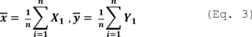
Where:
X1 = The PM CPMS data points for the three runs constituting the performance test.
Y1 = The PM concentration value for the three runs constituting the performance test.
n = The number of data points.
(C) With your instrument zero expressed in milliamps or a digital value, your three run average PM CPMS milliamp or digital signal value, and your three run PM compliance test average, determine a relationship of lb/ton-clinker per milliamp or digital signal value with Equation 4.
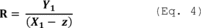
Where:
R = The relative lb/ton-clinker per milliamp or digital equivalent for your PM CPMS.
Y1 = The three run average lb/ton-clinker PM concentration.
X1 = The three run average milliamp or digital equivalent output from your PM CPMS.
z = The milliamp or digital equivalent of your instrument zero determined from (b)(1)(iii)(A).
(D) Determine your source specific 30-day rolling average operating limit using the lb/ton-clinker per milliamp or digital signal value from Equation 4 in Equation 5, below. This sets your operating limit at the PM CPMS output value corresponding to 75 percent of your emission limit.
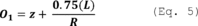
Where:
Ol = The operating limit for your PM CPMS on a 30-day rolling average, in milliamps or the digital equivalent.
L = Your source emission limit expressed in lb/ton clinker.
z = Your instrument zero in milliamps, or digital equivalent, determined from (b)(1)(iii)(A).
R = The relative lb/ton-clinker per milliamp, or digital equivalent, for your PM CPMS, from Equation 4.
(iv) If the average of your three PM compliance test runs is at or above 75 percent of your PM emission limit you must determine your operating limit by averaging the PM CPMS milliamp or digital equivalent output corresponding to your three PM performance test runs that demonstrate compliance with the emission limit using Equation 6.
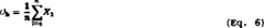
Where:
X1 = The PM CPMS data points for all runs i.
n = The number of data points.
Oh = Your site specific operating limit, in milliamps or the digital equivalent.
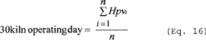
(v) To determine continuous operating compliance, you must record the PM CPMS output data for all periods when the process is operating, and use all the PM CPMS data for calculations when the source is not out-of-control. You must demonstrate continuous compliance by using all quality-assured hourly average data collected by the PM CPMS for all operating hours to calculate the arithmetic average operating parameter in units of the operating limit (milliamps or the digital equivalent) on a 30 operating day rolling average basis, updated at the end of each new kiln operating day. Use Equation 7 to determine the 30 kiln operating day average.
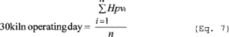
Where:
Hpvi = The hourly parameter value for hour i.
n = The number of valid hourly parameter values collected over 30 kiln operating days.
(vi) For each performance test, conduct at least three separate test runs under the conditions that exist when the affected source is operating at the level reasonably expected to occur. Conduct each test run to collect a minimum sample volume of 2 dscm for determining compliance with a new source limit and 1 dscm for determining compliance with an existing source limit. Calculate the time weighted average of the results from three consecutive runs, including applicable sources as required by paragraph (b)(1)(viii) of this section, to determine compliance. You need not determine the particulate matter collected in the impingers “back half” of the Method 5 or Method 5I particulate sampling train to demonstrate compliance with the PM standards of this subpart. This shall not preclude the permitting authority from requiring a determination of the “back half” for other purposes. For kilns with inline raw mills, testing must be conducted while the raw mill is on and while the raw mill is off. If the exhaust streams of a kiln with an inline raw mill and a clinker cooler are comingled, then the comingled exhaust stream must be tested with the raw mill on and the raw mill off.
(vii) For PM performance test reports used to set a PM CPMS operating limit, the electronic submission of the test report must also include the make and model of the PM CPMS instrument, serial number of the instrument, analytical principle of the instrument (e.g. beta attenuation), span of the instruments primary analytical range, milliamp value or digital equivalent to the instrument zero output, technique by which this zero value was determined, and the average milliamp or digital equivalent signals corresponding to each PM compliance test run.
(viii) When there is an alkali bypass and/or an inline coal mill with a separate stack associated with a kiln, the main exhaust and alkali bypass and/or inline coal mill must be tested simultaneously and the combined emission rate of PM from the kiln and alkali bypass and/or inline coal mill must be computed for each run using Equation 8 of this section.
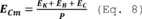
Where:
ECm = Combined hourly emission rate of PM from the kiln and bypass stack and/or inline coal mill, lb/ton of kiln clinker production.
EK = Hourly emissions of PM emissions from the kiln, lb.
EB = Hourly PM emissions from the alkali bypass stack, lb.
EC = Hourly PM emissions from the inline coal mill stack, lb.
P = Hourly clinker production, tons.
(ix) The owner or operator of a kiln with an in-line raw mill and subject to limitations on PM emissions shall demonstrate initial compliance by conducting separate performance tests while the raw mill is under normal operating conditions and while the raw mill is not operating, and calculate the time weighted average emissions. The operating limit will then be determined using 63.1349(b)(1)(i) of this section.
(2) Opacity tests. If you are subject to limitations on opacity under this subpart, you must conduct opacity tests in accordance with Method 9 of appendix A-4 to part 60 of this chapter. The duration of the Method 9 performance test must be 3 hours (30 6-minute averages), except that the duration of the Method 9 performance test may be reduced to 1 hour if the conditions of paragraphs (b)(2)(i) and (ii) of this section apply. For batch processes that are not run for 3-hour periods or longer, compile observations totaling 3 hours when the unit is operating.
(i) There are no individual readings greater than 10 percent opacity;
(ii) There are no more than three readings of 10 percent for the first 1-hour period.
(3) D/F Emissions Tests. If you are subject to limitations on D/F emissions under this subpart, you must conduct a performance test using Method 23 of appendix A-7 to part 60 of this chapter. If your kiln or in-line kiln/raw mill is equipped with an alkali bypass, you must conduct simultaneous performance tests of the kiln or in-line kiln/raw mill exhaust and the alkali bypass. You may conduct a performance test of the alkali bypass exhaust when the raw mill of the in-line kiln/raw mill is operating or not operating.
(i) Each performance test must consist of three separate runs conducted under representative conditions. The duration of each run must be at least 3 hours, and the sample volume for each run must be at least 2.5 dscm (90 dscf).
(ii) The temperature at the inlet to the kiln or in-line kiln/raw mill PMCD, and, where applicable, the temperature at the inlet to the alkali bypass PMCD must be continuously recorded during the period of the Method 23 test, and the continuous temperature record(s) must be included in the performance test report.
(iii) Average temperatures must be calculated for each run of the performance test.
(iv) The run average temperature must be calculated for each run, and the average of the run average temperatures must be determined and included in the performance test report and will determine the applicable temperature limit in accordance with §63.1346(b).
(v)(A) If sorbent injection is used for D/F control, you must record the rate of sorbent injection to the kiln exhaust, and where applicable, the rate of sorbent injection to the alkali bypass exhaust, continuously during the period of the Method 23 test in accordance with the conditions in §63.1350(m)(9), and include the continuous injection rate record(s) in the performance test report. Determine the sorbent injection rate parameters in accordance with paragraph (b)(3)(vi) of this section.
(B) Include the brand and type of sorbent used during the performance test in the performance test report.
(C) Maintain a continuous record of either the carrier gas flow rate or the carrier gas pressure drop for the duration of the performance test. If the carrier gas flow rate is used, determine, record, and maintain a record of the accuracy of the carrier gas flow rate monitoring system according to the procedures in appendix A to part 75 of this chapter. If the carrier gas pressure drop is used, determine, record, and maintain a record of the accuracy of the carrier gas pressure drop monitoring system according to the procedures in §63.1350(m)(6).
(vi) Calculate the run average sorbent injection rate for each run and determine and include the average of the run average injection rates in the performance test report and determine the applicable injection rate limit in accordance with §63.1346(c)(1).
(4) THC emissions test. (i) If you are subject to limitations on THC emissions, you must operate a CEMS in accordance with the requirements in §63.1350(i). For the purposes of conducting the accuracy and quality assurance evaluations for CEMS, the THC span value (as propane) is 50 to 60 ppmvw and the reference method (RM) is Method 25A of appendix A to part 60 of this chapter.
(ii) Use the THC CEMS to conduct the initial compliance test for the first 30 kiln operating days of kiln operation after the compliance date of the rule. See §63.1348(a).
(iii) If kiln gases are diverted through an alkali bypass or to a coal mill and exhausted through a separate stack, you must calculate a kiln-specific THC limit using Equation 9:

Where:
Cks = Kiln stack concentration (ppmvd).
Qab = Alkali bypass flow rate (volume/hr).
Cab = Alkali bypass concentration (ppmvd).
Qcm = Coal mill flow rate (volume/hr).
Ccm = Coal mill concentration (ppmvd).
Qks = Kiln stack flow rate (volume/hr).
(iv) THC must be measured either upstream of the coal mill or the coal mill stack.
(v) Instead of conducting the performance test specified in paragraph (b)(4)of this section, you may conduct a performance test to determine emissions of total organic HAP by following the procedures in paragraph (b)(7) of this section.
(5) Mercury Emissions Tests. If you are subject to limitations on mercury emissions, you must operate a mercury CEMS or a sorbent trap monitoring system in accordance with the requirements of §63.1350(k). The initial compliance test must be based on the first 30 kiln operating days in which the affected source operates using a mercury CEMS or a sorbent trap monitoring system after the compliance date of the rule. See §63.1348(a).
(i) If you are using a mercury CEMS or a sorbent trap monitoring system, you must install, operate, calibrate, and maintain an instrument for continuously measuring and recording the exhaust gas flow rate to the atmosphere according to the requirements in §63.1350(k)(5).
(ii) Calculate the emission rate using Equation 10 of this section:
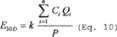
Where:
E30D = 30-day rolling emission rate of mercury, lb/MM tons clinker.
Ci = Concentration of mercury for operating hour i, µg/scm.
Qi = Volumetric flow rate of effluent gas for operating hour i, where Ci and Qi are on the same basis (either wet or dry), scm/hr.
k = Conversion factor, 1 lb/454,000,000 µg.
n = Number of kiln operating hours in the previous 30 kiln operating day period where both C and Qi qualified data are available.
P = Total runs from the previous 30 days of clinker production during the same time period as the mercury emissions measured, million tons.
(6) HCl emissions tests. For a source subject to limitations on HCl emissions you must conduct performance testing by one of the following methods:
(i)(A) If the source is equipped with a wet scrubber, tray tower or dry scrubber, you must conduct performance testing using Method 321 of appendix A to this part unless you have installed a CEMS that meets the requirements §63.1350(l)(1). For kilns with inline raw mills, testing must be conducted for the raw mill on and raw mill off conditions.
(B) You must establish site specific parameter limits by using the CPMS required in §63.1350(l)(1). For a wet scrubber or tray tower, measure and record the pressure drop across the scrubber and/or liquid flow rate and pH in intervals of no more than 15 minutes during the HCl test. Compute and record the 24-hour average pressure drop, pH, and average scrubber water flow rate for each sampling run in which the applicable emissions limit is met. For a dry scrubber, measure and record the sorbent injection rate in intervals of no more than 15 minutes during the HCl test. Compute and record the 24-hour average sorbent injection rate and average sorbent injection rate for each sampling run in which the applicable emissions limit is met.
(ii)(A) If the source is not controlled by a wet scrubber, tray tower or dry sorbent injection system, you must operate a CEMS in accordance with the requirements of §63.1350(l)(1). See §63.1348(a).
(B) The initial compliance test must be based on the 30 kiln operating days that occur after the compliance date of this rule in which the affected source operates using an HCl CEMS. Hourly HCl concentration data must be obtained according to §63.1350(l).
(iii) As an alternative to paragraph (b)(6)(i)(B) of this section, you may choose to monitor SO2 emissions using a CEMS in accordance with the requirements of §63.1350(l)(3). You must establish an SO2 operating limit equal to the average recorded during the HCl stack test where the HCl stack test run result demonstrates compliance with the emission limit. This operating limit will apply only for demonstrating HCl compliance.
(iv) If kiln gases are diverted through an alkali bypass or to a coal mill and exhausted through a separate stack, you must calculate a kiln-specific HCl limit using Equation 11:

Where:
Cks = Kiln stack concentration (ppmvd).
Qab = Alkali bypass flow rate (volume/hr).
Cab = Alkali bypass concentration (ppmvd).
Qcm = Coal mill flow rate (volume/hr).
Ccm = Coal mill concentration (ppmvd).
Qks = Kiln stack flow rate (volume/hr).
(v) As an alternative to paragraph (b)(6)(ii) of this section, the owner or operator may demonstrate initial compliance by conducting a performance test using Method 321 of appendix A to this part. You must also monitor continuous performance through use of an HCl CPMS according to paragraphs (b)(6)(v)(A) through (H) of this section. For kilns with inline raw mills, compliance testing and monitoring HCl to establish the site specific operating limit must be conducted during both raw mill on and raw mill off conditions.
(A) For your HCl CPMS, you must establish a 30 kiln operating day site-specific operating limit. If your HCl performance test demonstrates your HCl emission levels to be less than 75 percent of your emission limit (2.25 ppmvd @7% O2), you must use the time weighted average HCl CPMS indicated value recorded during the HCl compliance test (typically measured as ppmvw HCl at stack O2 concentration, but a dry, oxygen corrected value would also suffice), your HCl instrument zero output value, and the time weighted average HCl result of your compliance test to establish your operating limit. If your HCl compliance test demonstrates your HCl emission levels to be at or above 75 percent of your emission limit (2.25 ppmvd @7% O2), you must use the time weighted average HCl CPMS indicated value recorded during the HCl compliance test as your operating limit. You must use the HCl CPMS indicated signal data to demonstrate continuous compliance with your operating limit.
(1) Your HCl CPMS must provide a ppm HCl concentration output and the establishment of its relationship to manual reference method measurements must be determined in units of indicated ppm. The instrument signal may be in ppmvw or ppmvd and the signal may be a measurement of HCl at in-stack concentration or a corrected oxygen concentration. Once the relationship between the indicated output of the HCl CPMS and the reference method test results is established, the HCl CPMS instrument measurement basis (ppmvw or ppmvd, or oxygen correction basis) must not be altered. Likewise, any setting that impacts the HCl CPMS indicated HCl response must remain fixed after the site-specific operating limit is set.
(2) Your HCl CPMS operating range must be capable of reading HCl concentrations from zero to a level equivalent to 125 percent of the highest expected value during mill off operation. If your HCl CPMS is an auto-ranging instrument capable of multiple scales, the primary range of the instrument must be capable of reading an indicated HCl concentration from zero to 10 ppm.
(3) During the initial performance test of a kiln with an inline raw mill, or any such subsequent performance test that demonstrates compliance with the HCl limit, record and average the indicated ppm HCl output values from the HCl CPMS for each of the six periods corresponding to the compliance test runs (e.g., average each of your HCl CPMS output values for six corresponding Method 321 test runs). With the average values of the six test runs, calculate the average of the three mill on test runs and the average of the three mill off test runs. Calculate the time weighted result using the average of the three mill on tests and the average of the three mill off tests and the previous annual ratio of mill on/mill off operations. Kilns without an inline raw mill will conduct three compliance tests and calculate the average monitor output values corresponding to these three test runs and not use time weighted values to determine their site specific operating limit.
(B) Determine your operating limit as specified in paragraphs (b)(6)(i) or (iii) of this section. If your HCl performance test demonstrates your HCl emission levels to be below 75 percent of your emission limit, kilns with inline raw mills will use the time weighted average indicated HCl ppm concentration CPMS value recorded during the HCl compliance test, the zero value output from your HCl CPMS, and the time weighted average HCl result of your compliance test to establish your operating limit. Kilns without inline raw mills will not use a time weighted average value to establish their operating limit. If your time weighted HCl compliance test demonstrates your HCl emission levels to be at or above 75 percent of your emission limit, you will use the time weighted HCl CPMS indicated ppm value recorded during the HCl compliance test to establish your operating limit. Kilns without inline raw mills will not use time weighted compliance test results to make this determination. You must verify an existing operating limit or establish a new operating limit for each kiln, after each repeated performance test.
(C) If the average of your three Method 321 compliance test runs (for kilns without an inline raw mill) or the time weighted average of your six Method 321 compliance test runs (for an kiln with an inline raw mill) is below 75 percent of your HCl emission limit, you must calculate an operating limit by establishing a relationship of the average HCl CPMS indicated ppm to the Method 321 test average HCl concentration using the HCl CPMS instrument zero, the average HCl CPMS indicated values corresponding to the three (for kilns without inline raw mills) or time weighted HCl CPMS indicated values corresponding to the six (for kilns with inline raw mills) compliance test runs, and the average HCl concentration (for kilns without raw mills) or average time weighted HCl concentration (for kilns with inline raw mills) from the Method 321 compliance test with the procedures in paragraphs (b)(6)(v)(C)(1) through (5) of this section.
(1) Determine your HCl CPMS instrument zero output with one of the following procedures:
(i) Zero point data for in situ instruments should be obtained by removing the instrument from the stack and monitoring ambient air on a test bench.
(ii) If neither of the steps in paragraphs (b)(6)(v)(C)(1)(i) through (ii) of this section are possible, you must use a zero output value provided by the manufacturer.
(2) If your facility does not have an inline raw mill you will determine your HCl CPMS indicated average in HCl ppm, and the average of your corresponding three HCl compliance test runs, using equation 11a.

Where:
Xi = The HCl CPMS data points for the three (or six) runs constituting the performance test;
Yi = The HCl concentration value for the three (or six) runs constituting the performance test; and
n = The number of data points.
(3) You will determine your HCl CPMS indicated average in HCl ppm, and the average of your corresponding HCl compliance test runs, using equation 11b. If you have an inline raw mill, use this same equation to calculate a second three-test average for your mill off CPMS and compliance test data.

Where:
Xi = The HCl CPMS data points for the three runs constituting the mill on OR mill off performance test;
Yi = The HCl concentration value for the three runs constituting the mill on OR mill off performance test; and
n = The number of data points.
(4) With your instrument zero expressed in ppm, your average HCl CPMS ppm value, and your HCl compliance test average, determine a relationship of performance test HCl (as ppmvd @7% O2) concentration per HCl CPMS indicated ppm with Equation 11c.
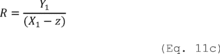
Where:
R = The relative performance test concentration per indicated ppm for your HCl CPMS;
Y1 = The average HCl concentration as ppmvd @7% O2 during the performance test;
X1 = The average indicated ppm output from your HCl CPMS; and
z = The ppm of your instrument zero determined from paragraph (b)(6)(v)(C)(1) of this section.
(5) Determine your source specific 30 kiln operating day operating limit using HC1 CPMS indicated value from Equation 11c in Equation 11d, below. This sets your operating limit at the HC1 CPMS output value corresponding to 75 percent of your emission limit.
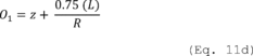
Where:
Ol = The operating limit for your HCl CPMS on a 30 kiln operating day average, as indicated ppm;
L = 3 ppmvd @7% O2;
z = Your instrument zero, determined from paragraph (b)(6)(v)(C)(1) of this section ; and
R = The relative performance test concentration per indicated ppm for your HCl CPMS, from Equation 11c.
(D) If the average of your HCl compliance test runs is at or above 75 percent of your HCl emission limit (2.25 ppmvd@7% O2) you must determine your operating limit by averaging the HCl CPMS output corresponding to your HCl performance test runs that demonstrate compliance with the emission limit using Equation 11e.
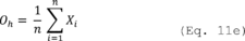
Where:
Oh = Your site specific HCl CPMS operating limit, in indicated ppm.
Xi = The HCl CPMS data points for all runs i.
n = The number of data points.
(E) To determine continuous compliance with the operating limit, you must record the HCl CPMS indicated output data for all periods when the process is operating and use all the HCl CPMS data for calculations when the source is not out of control. You must demonstrate continuous compliance with the operating limit by using all quality-assured hourly average data collected by the HCl CPMS for all operating hours to calculate the arithmetic average operating parameter in units of the operating limit (ppmvw) on a 30 kiln operating day rolling average basis, updated at the end of each new kiln operating day. Use Equation 11f to determine the 30 kiln operating day average.
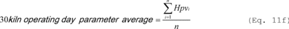
Where:
30 kiln operating day parameter average = The average indicated value for the CPMS parameter over the previous 30 days of kiln operation;
Hpvi = The hourly parameter value for hour i; and
n = The number of valid hourly parameter values collected over 30 kiln operating days.
(F) If you exceed the 30 kiln operating day operating limit, you must evaluate the control system operation and re-set the operating limit.
(G) The owner or operator of a kiln with an inline raw mill and subject to limitations on HCl emissions must demonstrate initial compliance by conducting separate performance tests while the raw mill is on and while the raw mill is off. Using the fraction of time the raw mill is on calculate your HCl CPMS limit as a weighted average of the HCl CPMS indicated values measured during raw mill on and raw mill off compliance testing using Equation 11g.

Where:
R = HCl CPMS operating limit;
b = Average indicated HCl CPMS value during mill on operations, ppm;
t = Fraction of operating time with mill on;
a = Average indicated HCl CPMS value during mill off operations ppm; and
(1−t) = Fraction of operating time with mill off.
(H) Paragraph (b)(6)(v) of this section expires on July 25, 2017 at which time the owner or operator must demonstrate compliance with paragraphs (b)(6)(i), (ii), or (iii).
(7) Total Organic HAP Emissions Tests. Instead of conducting the performance test specified in paragraph (b)(4) of this section, you may conduct a performance test to determine emissions of total organic HAP by following the procedures in paragraphs (b)(7)(i) through (v) of this section.
(i) Use Method 320 of appendix A to this part, Method 18 of Appendix A of part 60, ASTM D6348-03 or a combination to determine emissions of total organic HAP. Each performance test must consist of three separate runs under the conditions that exist when the affected source is operating at the representative performance conditions in accordance with §63.7(e). Each run must be conducted for at least 1 hour.
(ii) At the same time that you are conducting the performance test for total organic HAP, you must also determine a site-specific THC emissions limit by operating a THC CEMS in accordance with the requirements of §63.1350(j). The duration of the performance test must be at least 3 hours and the average THC concentration (as calculated from the recorded output) during the 3-hour test must be calculated. You must establish your THC operating limit and determine compliance with it according to paragraphs (b)(7)(vii) and (viii) of this section. It is permissible to extend the testing time of the organic HAP performance test if you believe extended testing is required to adequately capture organic HAP and/or THC variability over time.
(iii) If your source has an in-line kiln/raw mill you must use the fraction of time the raw mill is on and the fraction of time that the raw mill is off and calculate this limit as a weighted average of the THC levels measured during three raw mill on and three raw mill off tests.
(iv) If your organic HAP emissions are below 75 percent of the organic HAP standard and you determine your operating limit with paragraph (b)(7)(vii) of this section your THC CEMS must be calibrated and operated on a measurement scale no greater than 180 ppmvw, as carbon, or 60 ppmvw as propane.
(v) If your kiln has an inline coal mill and/or an alkali bypass with separate stacks, you are required to measure and account for oHAP emissions from their separate stacks. You are required to measure oHAP at the coal mill inlet or outlet and you must also measure oHAP at the alkali bypass outlet. You must then calculate a flow weighted average oHAP concentration for all emission sources including the inline coal mill and the alkali bypass.
(vi) Your THC CEMS measurement scale must be capable of reading THC concentrations from zero to a level equivalent to two times your highest THC emissions average determined during your performance test, including mill on or mill off operation. Note: This may require the use of a dual range instrument to meet this requirement and paragraph (b)(7)(iv) of this section.
(vii) Determine your operating limit as specified in paragraphs (b)(7)(viii) and (ix) of this section. If your organic HAP performance test demonstrates your average organic HAP emission levels are below 75 percent of your emission limit (9 ppmv) you will use the average THC value recorded during the organic HAP performance test, and the average total organic HAP result of your performance test to establish your operating limit. If your organic HAP compliance test results demonstrate that your average organic HAP emission levels are at or above 75 percent of your emission limit, your operating limit is established as the average THC value recorded during the organic HAP performance test. You must establish a new operating limit after each performance test. You must repeat the performance test no later than 30 months following your last performance test and reassess and adjust the site-specific operating limit in accordance with the results of the performance test.
(viii) If the average organic HAP results for your three Method 18 and/or Method 320 performance test runs are below 75 percent of your organic HAP emission limit, you must calculate an operating limit by establishing a relationship of THC CEMS signal to the organic HAP concentration using the average THC CEMS value corresponding to the three organic HAP compliance test runs and the average organic HAP total concentration from the Method 18 and/or Method 320 performance test runs with the procedures in (b)(7)(viii)(A) and (B) of this section.
(A) Determine the THC CEMS average value in ppmvw, and the average of your corresponding three total organic HAP compliance test runs, using Equation 12.
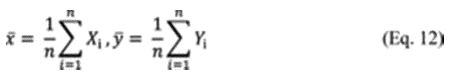
Where:
x = The average THC CEMS value in ppmvw, as propane.
Xi = The THC CEMS data points in ppmvw, as propane, for all three test runs.
y = The average organic HAP value in ppmvd, corrected to 7 percent oxygen.
Yi = The organic HAP concentrations in ppmvd, corrected to 7 percent oxygen, for all three test runs.
n = The number of data points.
(B) You must use your 3-run average THC CEMS value and your 3-run average organic HAP concentration from your Method 18 and/or Method 320 compliance tests to determine the operating limit. Use equation 13 to determine your operating limit in units of ppmvw THC, as propane.

Where:
Tl = The 30-day operating limit for your THC CEMS, ppmvw, as propane.
y = The average organic HAP concentration from Eq. 12, ppmvd, corrected to 7 percent oxygen.
x = The average THC CEMS concentration from Eq. 12, ppmvw, as propane.
9 = 75 percent of the organic HAP emissions limit (12 ppmvd, corrected to 7 percent oxygen)
(ix) If the average of your three organic HAP performance test runs is at or above 75 percent of your organic HAP emission limit, you must determine your operating limit using Equation 14 by averaging the THC CEMS output values corresponding to your three organic HAP performance test runs that demonstrate compliance with the emission limit. If your new THC CEMS value is below your current operating limit, you may opt to retain your current operating limit, but you must still submit all performance test and THC CEMS data according to the reporting requirements in paragraph (d)(1) of this section.
Where:
X1 = The THC CEMS data points for all runs i.
n = The number of data points.
Th = Your site specific operating limit, in ppmvw THC.
(x) If your kiln has an inline kiln/raw mill, you must conduct separate performance tests while the raw mill is operating (“mill on”) and while the raw mill is not operating (“mill off”). Using the fraction of time the raw mill is on and the fraction of time that the raw mill is off, calculate this limit as a weighted average of the THC levels measured during raw mill on and raw mill off compliance testing with Equation 15.

Where:
R = Operating limit as THC, ppmvw.
y = Average THC CEMS value during mill on operations, ppmvw.
t = Percentage of operating time with mill on.
x = Average THC CEMS value during mill off operations, ppmvw.
(1-t) = Percentage of operating time with mill off.
(xi) To determine continuous compliance with the THC operating limit, you must record the THC CEMS output data for all periods when the process is operating and the THC CEMS is not out-of-control. You must demonstrate continuous compliance by using all quality-assured hourly average data collected by the THC CEMS for all operating hours to calculate the arithmetic average operating parameter in units of the operating limit (ppmvw) on a 30 operating day rolling average basis, updated at the end of each new kiln operating day. Use Equation 16 to determine the 30 kiln operating day average.
Where:
Hpvi = The hourly parameter value for hour i, ppmvw.
n = The number of valid hourly parameter values collected over 30 kiln operating days.
(xii) Use EPA Method 18 or Method 320 of appendix A to part 60 of this chapter to determine organic HAP emissions. For each performance test, conduct at least three separate runs under the conditions that exist when the affected source is operating at the level reasonably expected to occur. If your source has an in-line kiln/raw mill you must conduct three separate test runs with the raw mill on, and three separate runs under the conditions that exist when the affected source is operating at the level reasonably expected to occur with the mill off. Conduct each Method 18 test run to collect a minimum target sample equivalent to three times the method detection limit. Calculate the average of the results from three runs to determine compliance.
(xiii) If the THC level exceeds by 10 percent or more your site-specific THC emissions limit, you must
(A) As soon as possible but no later than 30 days after the exceedance, conduct an inspection and take corrective action to return the THC CEMS measurements to within the established value; and
(B) Within 90 days of the exceedance or at the time of the 30 month compliance test, whichever comes first, conduct another performance test to determine compliance with the organic HAP limit and to verify or re-establish your site-specific THC emissions limit.
(8) HCl Emissions Tests with SO2 Monitoring. If you choose to monitor SO2 emissions using a CEMS to demonstrate HCl compliance, follow the procedures in (b)(8)(i) through (ix) of this section and in accordance with the requirements of §63.1350(l)(3). You must establish an SO2 operating limit equal to the average recorded during the HCl stack test. This operating limit will apply only for demonstrating HCl compliance.
(i) Use Method 321 of appendix A to this part to determine emissions of HCl. Each performance test must consist of three separate runs under the conditions that exist when the affected source is operating at the representative performance conditions in accordance with §63.7(e). Each run must be conducted for at least one hour.
(ii) At the same time that you are conducting the performance test for HCl, you must also determine a site-specific SO2 emissions limit by operating an SO2 CEMS in accordance with the requirements of §63.1350(l). The duration of the performance test must be three hours and the average SO2 concentration (as calculated from the average output) during the 3-hour test must be calculated. You must establish your SO2 operating limit and determine compliance with it according to paragraphs (b)(8)(vii) and (viii) of this section.
(iii) If your source has an in-line kiln/raw mill you must use the fraction of time the raw mill is on and the fraction of time that the raw mill is off and calculate this limit as a weighted average of the SO2 levels measured during raw mill on and raw mill off testing.
(iv) Your SO2 CEMS must be calibrated and operated according to the requirements of §60.63(f).
(v) Your SO2 CEMS measurement scale must be capable of reading SO2 concentrations consistent with the requirements of §60.63(f), including mill on or mill off operation.
1-t = Percentage of operating time with mill off, expressed as a decimal.
(vi) If your kiln has an inline kiln/raw mill, you must conduct separate performance tests while the raw mill is operating (“mill on”) and while the raw mill is not operating (“mill off”). Using the fraction of time that the raw mill is on and the fraction of time that the raw mill is off, calculate this limit as a weighted average of the SO2 levels measured during raw mill on and raw mill off compliance testing with Equation 17.
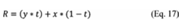
Where:
R = Operating limit as SO2, ppmv.
y = Average SO2 CEMS value during mill on operations, ppmv.
t = Percentage of operating time with mill on, expressed as a decimal.
x = Average SO2 CEMS value during mill off operations, ppmv.
1−t = Percentage of operating time with mill off, expressed as a decimal.
(vii) If the average of your three HCl compliance test runs is below 75 percent of your HCl emission limit, you may as a compliance alternative, calculate an operating limit by establishing a relationship of SO2 CEMS signal to your HCl concentration corrected to 7 percent O2 by using the SO2 CEMS instrument zero, the average SO2 CEMS values corresponding to the three compliance test runs, and the average HCl concentration from the HCl compliance test with the procedures in (b)(8)(vii)(A) through (D) of this section.
(A) Determine your SO2 CEMS instrument zero output with one of the following procedures:
(1) Zero point data for in-situ instruments should be obtained by removing the instrument from the stack and monitoring ambient air on a test bench.
(2) Zero point data for extractive instruments may be obtained by removing the extractive probe from the stack and drawing in clean ambient air.
(3) The zero point may also be established by performing probe-flood introduction of high purity nitrogen or certified zero air free of SO2.
(4) If none of the steps in paragraphs (b)(8)(vii)(A)(1) through (3) of this section are possible, you must use a zero output value provided by the manufacturer.
(B) Determine your SO2 CEMS instrument average ppmv, and the average of your corresponding three HCl compliance test runs, using Equation 18.
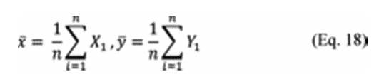
Where:
x = The average SO2 CEMS value in ppmv.
X1 = The SO2 CEMS data points in ppmv for the three runs constituting the performance test.
y = The average HCl value in ppmvd, corrected to 7 percent oxygen.
Y1 = The HCl emission concentration expressed as ppmvd, corrected to 7 percent oxygen for the threeruns constituting the performance test.
n = The number of data points.
(C) With your instrument zero expressed in ppmv, your SO2 CEMS three run average expressed in ppmv, and your 3-run HCl compliance test average in ppmvd, corrected to 7 percent O2, determine a relationship of ppmvd HCl corrected to 7 percent O2 per ppmv SO2 with Equation 19.
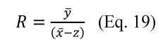
Where:
R = The relative HCl ppmvd, corrected to 7 percent oxygen, per ppmv SO2 for your SO2 CEMS.
y = The average HCl concentration from Eq. 18 in ppmvd, corrected to 7 percent oxygen.
x = The average SO2 CEMS value from Eq. 18 in ppmv.
z = The instrument zero output ppmv value.
(D) Determine your source specific 30-day rolling average operating limit using ppm HCl corrected to 7 percent O2 per ppm SO2 value from Equation 19 in Equation 20, below. This sets your operating limit at the SO2 CEMS ppm value corresponding to 75 percent of your emission limit.
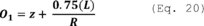
Where:
Ol = The operating limit for your SO2 CEMS on a 30-day rolling average, in ppmv.
L = Your source HCl emission limit expressed in ppmv corrected to 7 percent O2.
z = Your instrument zero in ppmv, determined from (1)(i).
R = The relative oxygen corrected ppmv HCl per ppmv SO2, for your SO2 CEMS, from Equation 19.
(viii) To determine continuous compliance with the SO2 operating limit, you must record the SO2 CEMS output data for all periods when the process is operating and the SO2 CEMS is not out-of-control. You must demonstrate continuous compliance by using all quality-assured hourly average data collected by the SO2 CEMS for all operating hours to calculate the arithmetic average operating parameter in units of the operating limit (ppmvw) on a 30 operating day rolling average basis, updated at the end of each new kiln operating day. Use Equation 21 to determine the 30 kiln operating day average.

Where:
Hpvi = The hourly parameter value for hour i, ppmvw.
n = The number of valid hourly parameter values collected over 30 kiln operating days.
(ix) Use EPA Method 321 of appendix A to part 60 of this chapter to determine HCl emissions. For each performance test, conduct at least three separate runs under the conditions that exist when the affected source is operating at the level reasonably expected to occur. If your source has an in-line kiln/raw mill you must conduct three separate test runs with the raw mill on, and three separate runs under the conditions that exist when the affected source is operating at the level reasonably expected to occur with the mill off.
(x) If the SO2 level exceeds by 10 percent or more your site-specific SO2 emissions limit, you must:
(A) As soon as possible but no later than 30 days after the exceedance, conduct an inspection and take corrective action to return the SO2 CEMS measurements to within the established value;
(B) Within 90 days of the exceedance or at the time of the periodic compliance test, whichever comes first, conduct another performance test to determine compliance with the HCl limit and to verify or re-establish your site-specific SO2 emissions limit.
(c) Performance test frequency. Except as provided in §63.1348(b), performance tests are required at regular intervals for affected sources that are subject to a dioxin, organic HAP or HCl emissions limit. Performance tests required every 30 months must be completed no more than 31 calendar months after the previous performance test except where that specific pollutant is monitored using CEMS; performance tests required every 12 months must be completed no more than 13 calendar months after the previous performance test.
(d) [Reseved]
(e) Conditions of performance tests. Conduct performance tests under such conditions as the Administrator specifies to the owner or operator based on representative performance of the affected source for the period being tested. Upon request, you must make available to the Administrator such records as may be necessary to determine the conditions of performance tests.
[75 FR 55057, Sept. 9, 2010, as amended at 78 FR 10040, Feb. 12, 2013; 80 FR 44781, July 27, 2015; 80 FR 54729, Sept. 11, 2015; 81 FR 48359, July 25, 2016; 82 FR 28565, June 23, 2017; 82 FR 39673, Aug. 22, 2017; 83 FR 35132, July 25, 2018; 85 FR 63419, Oct. 7, 2020]
(a)(1) Following the compliance date, the owner or operator must demonstrate compliance with this subpart on a continuous basis by meeting the requirements of this section.
(2) [Reserved]
(3) For each existing unit that is equipped with a CMS, maintain the average emissions or the operating parameter values within the operating parameter limits established through performance tests.
(4) Any instance where the owner or operator fails to comply with the continuous monitoring requirements of this section is a violation.
(b) PM monitoring requirements. (1)(i) PM CPMS. You will use a PM CPMS to establish a site-specific operating limit corresponding to the results of the performance test demonstrating compliance with the PM limit. You will conduct your performance test using Method 5 or Method 5I at appendix A-3 to part 60 of this chapter. You will use the PM CPMS to demonstrate continuous compliance with this operating limit. You must repeat the performance test annually and reassess and adjust the site-specific operating limit in accordance with the results of the performance test using the procedures in §63.1349(b)(1) (i) through (vi) of this subpart. You must also repeat the test if you change the analytical range of the instrument, or if you replace the instrument itself or any principle analytical component of the instrument that would alter the relationship of output signal to in-stack PM concentration.
(ii) To determine continuous compliance, you must use the PM CPMS output data for all periods when the process is operating and the PM CPMS is not out-of-control. You must demonstrate continuous compliance by using all quality-assured hourly average data collected by the PM CPMS for all operating hours to calculate the arithmetic average operating parameter in units of the operating limit (milliamps) on a 30 operating day rolling average basis, updated at the end of each new kiln operating day.
(iii) For any exceedance of the 30 process operating day PM CPMS average value from the established operating parameter limit, you must:
(A) Within 48 hours of the exceedance, visually inspect the APCD;
(B) If inspection of the APCD identifies the cause of the exceedance, take corrective action as soon as possible and return the PM CPMS measurement to within the established value; and
(C) Within 30 days of the exceedance or at the time of the annual compliance test, whichever comes first, conduct a PM emissions compliance test to determine compliance with the PM emissions limit and to verify or re-establish the PM CPMS operating limit within 45 days. You are not required to conduct additional testing for any exceedances that occur between the time of the original exceedance and the PM emissions compliance test required under this paragraph.
(iv) PM CPMS exceedances leading to more than four required performance tests in a 12-month process operating period (rolling monthly) constitute a presumptive violation of this subpart.
(2) [Reserved]
(c) [Reserved]
(d) Clinker production monitoring requirements. In order to determine clinker production, you must:
(1) Determine hourly clinker production by one of two methods:
(i) Install, calibrate, maintain, and operate a permanent weigh scale system to measure and record weight rates in tons-mass per hour of the amount of clinker produced. The system of measuring hourly clinker production must be maintained within ±5 percent accuracy, or
(ii) Install, calibrate, maintain, and operate a permanent weigh scale system to measure and record weight rates in tons-mass per hour of the amount of feed to the kiln. The system of measuring feed must be maintained within ±5 percent accuracy. Calculate your hourly clinker production rate using a kiln-specific feed to clinker ratio based on reconciled clinker production determined for accounting purposes and recorded feed rates. Update this ratio monthly. Note that if this ratio changes at clinker reconciliation, you must use the new ratio going forward, but you do not have to retroactively change clinker production rates previously estimated.
(iii) [Reserved]
(2) Determine, record, and maintain a record of the accuracy of the system of measuring hourly clinker production (or feed mass flow if applicable) before initial use (for new sources) or by the effective compliance date of this rule (for existing sources). During each quarter of source operation, you must determine, record, and maintain a record of the ongoing accuracy of the system of measuring hourly clinker production (or feed mass flow).
(3) If you measure clinker production directly, record the daily clinker production rates; if you measure the kiln feed rates and calculate clinker production, record the hourly kiln feed and clinker production rates.
(4) Develop an emissions monitoring plan in accordance with paragraphs (p)(1) through (p)(4) of this section.
(e) [Reserved]
(f) Opacity monitoring requirements. If you are subject to a limitation on opacity under §63.1345, you must conduct required opacity monitoring in accordance with the provisions of paragraphs (f)(1)(i) through (vii) of this section and in accordance with your monitoring plan developed under §63.1350(p). You must also develop an opacity monitoring plan in accordance with paragraphs (p)(1) through (4) and paragraph (o)(5), if applicable, of this section.
(1)(i) You must conduct a monthly 10-minute visible emissions test of each affected source in accordance with Method 22 of appendix A-7 to part 60 of this chapter. The performance test must be conducted while the affected source is in operation.
(ii) If no visible emissions are observed in six consecutive monthly tests for any affected source, the owner or operator may decrease the frequency of performance testing from monthly to semi-annually for that affected source. If visible emissions are observed during any semi-annual test, you must resume performance testing of that affected source on a monthly basis and maintain that schedule until no visible emissions are observed in six consecutive monthly tests.
(iii) If no visible emissions are observed during the semi-annual test for any affected source, you may decrease the frequency of performance testing from semi-annually to annually for that affected source. If visible emissions are observed during any annual performance test, the owner or operator must resume performance testing of that affected source on a monthly basis and maintain that schedule until no visible emissions are observed in six consecutive monthly tests.
(iv) If visible emissions are observed during any Method 22 performance test, of appendix A-7 to part 60 of this chapter, you must conduct 30 minutes of opacity observations, recorded at 15-second intervals, in accordance with Method 9 of appendix A-4 to part 60 of this chapter. The Method 9 performance test, of appendix A-4 to part 60 of this chapter, must begin within 1 hour of any observation of visible emissions.
(v) Any totally enclosed conveying system transfer point, regardless of the location of the transfer point is not required to conduct Method 22 visible emissions monitoring under this paragraph. The enclosures for these transfer points must be operated and maintained as total enclosures on a continuing basis in accordance with the facility operations and maintenance plan.
(vi) If any partially enclosed or unenclosed conveying system transfer point is located in a building, you must conduct a Method 22 performance test, of appendix A-7 to part 60 of this chapter, according to the requirements of paragraphs (f)(1)(i) through (iv) of this section for each such conveying system transfer point located within the building, or for the building itself, according to paragraph (f)(1)(vii) of this section.
(vii) If visible emissions from a building are monitored, the requirements of paragraphs (f)(1)(i) through (f)(1)(iv) of this section apply to the monitoring of the building, and you must also test visible emissions from each side, roof, and vent of the building for at least 10 minutes.
(2)(i) For a raw mill or finish mill, you must monitor opacity by conducting daily visible emissions observations of the mill sweep and air separator PM control devices (PMCD) of these affected sources in accordance with the procedures of Method 22 of appendix A-7 to part 60 of this chapter. The duration of the Method 22 performance test must be 6 minutes.
(ii) Within 24 hours of the end of the Method 22 performance test in which visible emissions were observed, the owner or operator must conduct a follow up Method 22 performance test of each stack from which visible emissions were observed during the previous Method 22 performance test.
(iii) If visible emissions are observed during the follow-up Method 22 performance test required by paragraph (f)(2)(ii) of this section from any stack from which visible emissions were observed during the previous Method 22 performance test required by paragraph (f)(2)(i) of the section, you must then conduct an opacity test of each stack from which emissions were observed during the follow up Method 22 performance test in accordance with Method 9 of appendix A-4 to part 60 of this chapter. The duration of the Method 9 test must be 30 minutes.
(3) If visible emissions are observed during any Method 22 visible emissions test conducted under paragraphs (f)(1) or (2) of this section, you must initiate, within one-hour, the corrective actions specified in your operation and maintenance plan as required in §63.1347.
(4) The requirements under paragraph (f)(2) of this section to conduct daily Method 22 testing do not apply to any specific raw mill or finish mill equipped with a COMS or BLDS.
(i) If the owner or operator chooses to install a COMS in lieu of conducting the daily visible emissions testing required under paragraph (f)(2) of this section, then the COMS must be installed at the outlet of the PM control device of the raw mill or finish mill and the COMS must be installed, maintained, calibrated, and operated as required by the general provisions in subpart A of this part and according to PS-1 of appendix B to part 60 of this chapter.
(ii) If you choose to install a BLDS in lieu of conducting the daily visible emissions testing required under paragraph (f)(2) of this section, the requirements in paragraphs (m)(1) through (m)(4), (m)(10) and (m)(11) of this section apply.
(g) D/F monitoring requirements. If you are subject to an emissions limitation on D/F emissions, you must comply with the monitoring requirements of paragraphs (g)(1) through (5) and (m)(1) through (4) of this section to demonstrate continuous compliance with the D/F emissions standard. You must also develop an emissions monitoring plan in accordance with paragraphs (p)(1) through (4) of this section.
(1) You must install, calibrate, maintain, and continuously operate a CMS to record the temperature of the exhaust gases from the kiln and alkali bypass, if applicable, at the inlet to, or upstream of, the kiln and/or alkali bypass PMCDs.
(i) The temperature recorder response range must include zero and 1.5 times the average temperature established according to the requirements in §63.1349(b)(3)(iv).
(ii) The calibration reference for the temperature measurement must be a National Institute of Standards and Technology calibrated reference thermocouple-potentiometer system or alternate reference, subject to approval by the Administrator.
(iii) The calibration of all thermocouples and other temperature sensors must be verified at least once every three months.
(2) You must monitor and continuously record the temperature of the exhaust gases from the kiln and alkali bypass, if applicable, at the inlet to the kiln and/or alkali bypass PMCD.
(3) The required minimum data collection frequency must be one minute.
(4) Every hour, record the calculated rolling three-hour average temperature using the average of 180 successive one-minute average temperatures. See §63.1349(b)(3).
(5) When the operating status of the raw mill of the in-line kiln/raw mill is changed from off to on or from on to off, the calculation of the three-hour rolling average temperature must begin anew, without considering previous recordings.
(h) Monitoring requirements for sources using sorbent injection. If you are subject to an operating limit on D/F emissions that employs carbon injection as an emission control technique, you must comply with the additional monitoring requirements of paragraphs (h)(1) and (h)(2) and paragraphs (m)(1) through (m)(4) and (m)(9) of this section. You must also develop an emissions monitoring plan in accordance with paragraphs (p)(1) through (p)(4) of this section.
(1) Install, operate, calibrate, and maintain a continuous monitor to record the rate of activated carbon injection. The accuracy of the rate measurement device must be ±1 percent of the rate being measured.
(i) Verify the calibration of the device at least once every three months.
(ii) Each hour, calculate the three-hour rolling average activated carbon injection rate for the previous three hours of process operation. See §63.1349(b)(3).
(iii) When the operating status of the raw mill of the in-line kiln/raw mill is changed from off to on or from on to off, the calculation of the three-hour rolling average activated carbon injection rate must begin anew, without considering previous recordings.
(2)(i) Install, operate, calibrate, and maintain a continuous monitor to record the activated carbon injection system carrier gas parameter (either the carrier gas flow rate or the carrier gas pressure drop) established during the D/F performance test in accordance with §63.1349(b)(3).
(ii) Each hour, calculate the 3-hour rolling average of the selected parameter value for the previous 3 hours of process operation using all of the one-minute data available (i.e., the CMS is not out-of-control).
(i) THC Monitoring Requirements. If you are subject to an emissions limitation on THC emissions, you must comply with the monitoring requirements of paragraphs (i)(1) and (i)(2) and (m)(1) through (m)(4) of this section. You must also develop an emissions monitoring plan in accordance with paragraphs (p)(1) through (p)(4) of this section.
(1) You must install, operate, and maintain a THC continuous emission monitoring system in accordance with Performance Specification 8 or Performance Specification 8A of appendix B to part 60 of this chapter and comply with all of the requirements for continuous monitoring systems found in the general provisions, subpart A of this part. The owner or operator must operate and maintain each CEMS according to the quality assurance requirements in Procedure 1 of appendix F in part 60 of this chapter. For THC continuous emission monitoring systems certified under Performance Specification 8A, conduct the relative accuracy test audits required under Procedure 1 in accordance with Performance Specification 8, Sections 8 and 11 using Method 25A in appendix A to 40 CFR part 60 as the reference method; the relative accuracy must meet the criteria of Performance Specification 8, Section 13.2.
(2) Performance tests on alkali bypass and coal mill stacks must be conducted using Method 25A in appendix A to 40 CFR part 60 and repeated every 30 months.
(j) Total organic HAP monitoring requirements. If you are complying with the total organic HAP emissions limits, you must continuously monitor THC according to paragraphs (i)(1) and (2) of this section or in accordance with Performance Specification 8 or Performance Specification 8A of appendix B to part 60 of this chapter and comply with all of the requirements for continuous monitoring systems found in the general provisions, subpart A of this part. You must operate and maintain each CEMS according to the quality assurance requirements in Procedure 1 of appendix F in part 60 of this chapter. You must also develop an emissions monitoring plan in accordance with paragraphs (p)(1) through (4) of this section.
(k) Mercury monitoring requirements. If you have a kiln subject to an emissions limitation on mercury emissions, you must install and operate a mercury continuous emissions monitoring system (Hg CEMS) in accordance with Performance Specification 12A (PS 12A) of appendix B to part 60 of this chapter or an integrated sorbent trap monitoring system in accordance with Performance Specification 12B (PS 12B) of appendix B to part 60 of this chapter. You must monitor mercury continuously according to paragraphs (k)(1) through (5) of this section. You must also develop an emissions monitoring plan in accordance with paragraphs (p)(1) through (4) of this section.
(1) You must use a span value for any Hg CEMS that represents the mercury concentration corresponding to approximately two times the emissions standard and may be rounded up to the nearest multiple of 5 µg/m 3 of total mercury or higher level if necessary to include Hg concentrations which may occur (excluding concentrations during in-line raw “mill off” operation). As specified in PS 12A, Section 6.1.1, the data recorder output range must include the full range of expected Hg concentration values which would include those expected during “mill off” conditions. Engineering judgments made and calculations used to determine the corresponding span concentration from the emission standard shall be documented in the site-specific monitoring plan and associated records.
(2) In order to quality assure data measured above the span value, you must use one of the four options in paragraphs (k)(2)(i) through (iv) of this section.
(i) Include a second span that encompasses the Hg emission concentrations expected to be encountered during “mill off” conditions. This second span may be rounded to a multiple of 5 µg/m 3 of total mercury. The requirements of PS 12A, shall be followed for this second span with the exception that a RATA with the mill off is not required.
(ii) Quality assure any data above the span value by proving instrument linearity beyond the span value established in paragraph (k)(1) of this section using the following procedure. Conduct a weekly “above span linearity” calibration challenge of the monitoring system using a reference gas with a certified value greater than your highest expected hourly concentration or greater than 75 percent of the highest measured hourly concentration. The “above span” reference gas must meet the requirements of PS 12A, Section 7.1 and must be introduced to the measurement system at the probe. Record and report the results of this procedure as you would for a daily calibration. The “above span linearity” challenge is successful if the value measured by the Hg CEMS falls within 10 percent of the certified value of the reference gas. If the value measured by the Hg CEMS during the above span linearity challenge exceeds ±10 percent of the certified value of the reference gas, the monitoring system must be evaluated and repaired and a new “above span linearity” challenge met before returning the Hg CEMS to service, or data above span from the Hg CEMS must be subject to the quality assurance procedures established in paragraph (k)(2)(iii) of this section. In this manner all hourly average values exceeding the span value measured by the Hg CEMS during the week following the above span linearity challenge when the CEMS response exceeds ±20 percent of the certified value of the reference gas must be normalized using Equation 22.

(iii) Quality assure any data above the span value established in paragraph (k)(1) of this section using the following procedure. Any time two consecutive 1-hour average measured concentrations of Hg exceeds the span value you must, within 24 hours before or after, introduce a higher, “above span” Hg reference gas standard to the Hg CEMS. The “above span” reference gas must meet the requirements of PS 12A, Section 7.1, must target a concentration level between 50 and 150 percent of the highest expected hourly concentration measured during the period of measurements above span, and must be introduced at the probe. While this target represents a desired concentration range that is not always achievable in practice, it is expected that the intent to meet this range is demonstrated by the value of the reference gas. Expected values may include “above span” calibrations done before or after the above span measurement period. Record and report the results of this procedure as you would for a daily calibration. The “above span” calibration is successful if the value measured by the Hg CEMS is within 20 percent of the certified value of the reference gas. If the value measured by the Hg CEMS exceeds 20 percent of the certified value of the reference gas, then you must normalize the one-hour average stack gas values measured above the span during the 24-hour period preceding or following the “above span” calibration for reporting based on the Hg CEMS response to the reference gas as shown in Equation 22. Only one “above span” calibration is needed per 24-hour period.
(3) You must operate and maintain each Hg CEMS or an integrated sorbent trap monitoring system according to the quality assurance requirements in Procedure 5 of appendix F to part 60 of this chapter. During the RATA of integrated sorbent trap monitoring systems required under Procedure 5, you may apply the appropriate exception for sorbent trap section 2 breakthrough in (k)(3)(i) through (iv) of this section:
(i) For stack Hg concentrations >1 µg/dscm, ≤10% of section 1 mass;
(ii) For stack Hg concentrations ≤1 µg/dscm and >0.5 µg/dscm, ≤20% of section 1 mass;
(iii) For stack Hg concentrations ≤0.5 µg/dscm and >0.1 µg/dscm, ≤50% of section 1 mass; and
(iv) For stack Hg concentrations ≤0.1 µg/dscm, no breakthrough criterion assuming all other QA/QC specifications are met.
(4) Relative accuracy testing of mercury monitoring systems under PS 12A, PS 12B, or Procedure 5 must be conducted at normal operating conditions. If a facility has an inline raw mill, the testing must occur with the raw mill on.
(5) If you use a Hg CEMS or an integrated sorbent trap monitoring system, you must install, operate, calibrate, and maintain an instrument for continuously measuring and recording the exhaust gas flow rate to the atmosphere according to the requirements in paragraphs (n)(1) through (10) of this section. If kiln gases are diverted through an alkali bypass or to a coal mill and exhausted through separate stacks, you must account for the mercury emitted from those stacks by following the procedures in (k)(5)(i) through (iv) of this section:
(i) Develop a mercury hourly mass emissions rate by conducting performance tests annually, within 11 to 13 calendar months after the previous performance test, using Method 29, or Method 30B, to measure the concentration of mercury in the gases exhausted from the alkali bypass and coal mill.
(ii) On a continuous basis, determine the mass emissions of mercury in lb/hr from the alkali bypass and coal mill exhausts by using the mercury hourly emissions rate and the exhaust gas flow rate to calculate hourly mercury emissions in lb/hr.
(iii) Sum the hourly mercury emissions from the kiln, alkali bypass and coal mill to determine total mercury emissions. Using hourly clinker production, calculate the hourly emissions rate in pounds per ton of clinker to determine your 30 day rolling average.
(iv) If mercury emissions from the coal mill and alkali bypass are below the method detection limit for two consecutive annual performance tests, you may reduce the frequency of the performance tests of coal mills and alkali bypasses to once every 30 months. If the measured mercury concentration exceeds the method detection limit, you must revert to testing annually until two consecutive annual tests are below the method detection limit.
(6) If you operate an integrated sorbent trap monitoring system conforming to PS 12B, you may use a monitoring period at least 24 hours but no longer than 168 hours in length. You should use a monitoring period that is a multiple of 24 hours (except during relative accuracy testing as allowed in PS 12B).
(l) HCl Monitoring Requirements. If you are subject to an emissions limitation on HCl emissions in §63.1343, you must monitor HCl emissions continuously according to paragraph (l)(1) or (2) and paragraphs (m)(1) through (4) of this section or, if your kiln is controlled using a wet or dry scrubber or tray tower, you alternatively may parametrically monitor SO2 emissions continuously according to paragraph (l)(3) of this section. You must also develop an emissions monitoring plan in accordance with paragraphs (p)(1) through (4) of this section.
(1) If you monitor compliance with the HCl emissions limit by operating an HCl CEMS, you must do so in accordance with Performance Specification (PS) 15 or PS 18 of appendix B to part 60 of this chapter, or, upon promulgation, in accordance with any other performance specification for HCl CEMS in appendix B to part 60 of this chapter. You must operate, maintain, and quality assure a HCl CEMS installed and certified under PS 15 according to the quality assurance requirements in Procedure 1 of appendix F to part 60 of this chapter except that the Relative Accuracy Test Audit requirements of Procedure 1 must be replaced with the validation requirements and criteria of sections 11.1.1 and 12.0 of PS 15. If you choose to install and operate an HCl CEMS in accordance with PS 18, you must operate, maintain, and quality assure the HCl CEMS using the associated Procedure 6 of appendix F to part 60 of this chapter. For any performance specification that you use, you must use Method 321 of appendix A to this part as the reference test method for conducting relative accuracy testing. The span value and calibration requirements in paragraphs (l)(1)(i) and (ii) of this section apply to HCl CEMS other than those installed and certified under PS 15 or PS 18.
(i) You must use a measurement span value for any HCl CEMS of 0-10 ppmvw unless the monitor is installed on a kiln without an inline raw mill. Kilns without an inline raw mill may use a higher span value sufficient to quantify all expected emissions concentrations. The HCl CEMS data recorder output range must include the full range of expected HCl concentration values which would include those expected during “mill off” conditions. The corresponding data recorder range shall be documented in the site-specific monitoring plan and associated records.
(ii) In order to quality assure data measured above the span value, you must use one of the three options in paragraphs (l)(1)(ii)(A) through (C) of this section.
(A) Include a second span that encompasses the HCl emission concentrations expected to be encountered during “mill off” conditions. This second span may be rounded to a multiple of 5 ppm of total HCl. The requirements of the appropriate HCl monitor performance specification shall be followed for this second span with the exception that a RATA with the mill off is not required.
(B) Quality assure any data above the span value by proving instrument linearity beyond the span value established in paragraph (l)(1)(i) of this section using the following procedure. Conduct a weekly “above span linearity” calibration challenge of the monitoring system using a reference gas with a certified value greater than your highest expected hourly concentration or greater than 75 percent of the highest measured hourly concentration. The “above span” reference gas must meet the requirements of the applicable performance specification and must be introduced to the measurement system at the probe. Record and report the results of this procedure as you would for a daily calibration. The “above span linearity” challenge is successful if the value measured by the HCl CEMS falls within 10 percent of the certified value of the reference gas. If the value measured by the HCl CEMS during the above span linearity challenge exceeds 10 percent of the certified value of the reference gas, the monitoring system must be evaluated and repaired and a new “above span linearity” challenge met before returning the HCl CEMS to service, or data above span from the HCl CEMS must be subject to the quality assurance procedures established in paragraph (l)(1)(ii)(D) of this section. Any HCl CEMS above span linearity challenge response exceeding ±20 percent of the certified value of the reference gas requires that all above span hourly averages during the week following the above span linearity challenge must be normalized using Equation 23.
(C) Quality assure any data above the span value established in paragraph (l)(1)(i) of this section using the following procedure. Any time two consecutive one-hour average measured concentration of HCl exceeds the span value you must, within 24 hours before or after, introduce a higher, “above span” HCl reference gas standard to the HCl CEMS. The “above span” reference gas must meet the requirements of the applicable performance specification and target a concentration level between 50 and 150 percent of the highest expected hourly concentration measured during the period of measurements above span, and must be introduced at the probe. While this target represents a desired concentration range that is not always achievable in practice, it is expected that the intent to meet this range is demonstrated by the value of the reference gas. Expected values may include above span calibrations done before or after the above-span measurement period. Record and report the results of this procedure as you would for a daily calibration. The “above span” calibration is successful if the value measured by the HCl CEMS is within 20 percent of the certified value of the reference gas. If the value measured by the HCl CEMS is not within 20 percent of the certified value of the reference gas, then you must normalize the stack gas values measured above span as described in paragraph (l)(1)(ii)(D) of this section.
(D) In theevent that the “above span” calibration is not successful (i.e., the HCl CEMS measured value is not within 20 percent of the certified value of the reference gas), then you must normalize the one-hour average stack gas values measured above the span during the 24-hour period preceding or following the `above span' calibration for reporting based on the HCl CEMS response to the reference gas as shown in Equation 23:
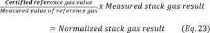
Only one “above span” calibration is needed per 24-hour period.
(2) Install, operate, and maintain a CMS to monitor wet scrubber or tray tower parameters, as specified in paragraphs (m)(5) and (7) of this section, and dry scrubber, as specified in paragraph (m)(9) of this section.
(3) If the source is equipped with a wet or dry scrubber or tray tower, and you choose to monitor SO2 emissions, monitor SO2 emissions continuously according to the requirements of §60.63(e) and (f) of this chapter. If SO2 levels increase above the 30-day rolling average SO2 operating limit established during your performance test by 10 percent or more, you must:
(i) As soon as possible but no later than 30 days after you exceed the established SO2 value conduct an inspection and take corrective action to return the SO2 emissions to within the operating limit; and
(ii) Within 90 days of the exceedance or at the time of the next compliance test, whichever comes first, conduct an HCl emissions compliance test to determine compliance with the HCl emissions limit and to verify or re-establish the SO2 CEMS operating limit.
(4) If you monitor continuous performance through the use of an HCl CPMS according to paragraphs (b)(6)(v)(A) through (H) of §63.1349, for any exceedance of the 30 kiln operating day HCl CPMS average value from the established operating limit, you must:
(i) Within 48 hours of the exceedance, visually inspect the APCD;
(ii) If inspection of the APCD identifies the cause of the exceedance, take corrective action as soon as possible and return the HCl CPMS measurement to within the established value; and
(iii) Within 30 days of the exceedance or at the time of the annual compliance test, whichever comes first, conduct an HCl emissions compliance test to determine compliance with the HCl emissions limit and to verify or reestablish the HCl CPMS operating limit within 45 days. You are not required to conduct additional testing for any exceedances that occur between the time of the original exceedance and the HCl emissions compliance test required under this paragraph.
(iv) HCl CPMS exceedances leading to more than four required performance tests in a 12-month process operating period (rolling monthly) constitute a presumptive violation of this subpart.
(m) Parameter monitoring requirements. If you have an operating limit that requires the use of a CMS, you must install, operate, and maintain each continuous parameter monitoring system (CPMS) according to the procedures in paragraphs (m)(1) through (4) of this section by the compliance date specified in §63.1351. You must also meet the applicable specific parameter monitoring requirements in paragraphs (m)(5) through (11) that are applicable to you.
(1) The CMS must complete a minimum of one cycle of operation for each successive 15-minute period. You must have a minimum of four successive cycles of operation to have a valid hour of data.
(2) You must conduct all monitoring in continuous operation at all times that the unit is operating.
(3) Determine the 1-hour block average of all recorded readings.
(4) Record the results of each inspection, calibration, and validation check.
(5) Liquid flow rate monitoring requirements. If you have an operating limit that requires the use of a flow measurement device, you must meet the requirements in paragraphs (m)(5)(i) through (iv) of this section.
(i) Locate the flow sensor and other necessary equipment in a position that provides a representative flow.
(ii) Use a flow sensor with a measurement sensitivity of 2 percent of the flow rate.
(iii) Reduce swirling flow or abnormal velocity distributions due to upstream and downstream disturbances.
(iv) Conduct a flow sensor calibration check at least semiannually.
(6) Specific pressure monitoring requirements. If you have an operating limit that requires the use of a pressure measurement device, you must meet the requirements in paragraphs (m)(6)(i) through (vi) of this section.
(i) Locate the pressure sensor(s) in a position that provides a representative measurement of the pressure.
(ii) Minimize or eliminate pulsating pressure, vibration, and internal and external corrosion.
(iii) Use a gauge with a minimum tolerance of 1.27 centimeters of water or a transducer with a minimum tolerance of 1 percent of the pressure range.
(iv) Check pressure tap pluggage daily.
(v) Using a manometer, check gauge calibration quarterly and transducer calibration monthly.
(vi) Conduct calibration checks any time the sensor exceeds the manufacturer's specified maximum operating pressure range or install a new pressure sensor.
(7) Specific pH monitoring requirements. If you have an operating limit that requires the use of a pH measurement device, you must meet the requirements in paragraphs (m)(7)(i) through (iii) of this section.
(i) Locate the pH sensor in a position that provides a representative measurement of wet scrubber or tray tower effluent pH.
(ii) Ensure the sample is properly mixed and representative of the fluid to be measured.
(iii) Check the pH meter's calibration on at least two points every 8 hours of process operation.
(8) [Reserved]
(9) Mass flow rate (for sorbent injection) monitoring requirements. If you have an operating limit that requires the use of equipment to monitor sorbent injection rate (e.g., weigh belt, weigh hopper, or hopper flow measurement device), you must meet the requirements in paragraphs (m)(9)(i) through (iii) of this section. These requirements also apply to the sorbent injection equipment of a dry scrubber.
(i) Locate the device in a position(s) that provides a representative measurement of the total sorbent injection rate.
(ii) Install and calibrate the device in accordance with manufacturer's procedures and specifications.
(iii) At least annually, calibrate the device in accordance with the manufacturer's procedures and specifications.
(10) Bag leak detection monitoring requirements. If you elect to use a fabric filter bag leak detection system to comply with the requirements of this subpart, you must install, calibrate, maintain, and continuously operate a BLDS as specified in paragraphs (m)(10)(i) through (viii) of this section.
(i) You must install and operate a BLDS for each exhaust stack of the fabric filter.
(ii) Each BLDS must be installed, operated, calibrated, and maintained in a manner consistent with the manufacturer's written specifications and recommendations and in accordance with the guidance provided in EPA-454/R-98-015, September 1997.
(iii) The BLDS must be certified by the manufacturer to be capable of detecting PM emissions at concentrations of 10 or fewer milligrams per actual cubic meter.
(iv) The BLDS sensor must provide output of relative or absolute PM loadings.
(v) The BLDS must be equipped with a device to continuously record the output signal from the sensor.
(vi) The BLDS must be equipped with an alarm system that will alert an operator automatically when an increase in relative PM emissions over a preset level is detected. The alarm must be located such that the alert is detected and recognized easily by an operator.
(vii) For positive pressure fabric filter systems that do not duct all compartments of cells to a common stack, a BLDS must be installed in each baghouse compartment or cell.
(viii) Where multiple bag leak detectors are required, the system's instrumentation and alarm may be shared among detectors.
(11) For each BLDS, the owner or operator must initiate procedures to determine the cause of every alarm within 8 hours of the alarm. The owner or operator must alleviate the cause of the alarm within 24 hours of the alarm by taking whatever corrective action(s) are necessary. Corrective actions may include, but are not limited to the following:
(i) Inspecting the fabric filter for air leaks, torn or broken bags or filter media, or any other condition that may cause an increase in PM emissions;
(ii) Sealing off defective bags or filter media;
(iii) Replacing defective bags or filter media or otherwise repairing the control device;
(iv) Sealing off a defective fabric filter compartment;
(v) Cleaning the BLDS probe or otherwise repairing the BLDS; or
(vi) Shutting down the process producing the PM emissions.
(n) Continuous Flow Rate Monitoring System. You must install, operate, calibrate, and maintain instruments, according to the requirements in paragraphs (n)(1) through (10) of this section, for continuously measuring and recording the stack gas flow rate to allow determination of the pollutant mass emissions rate to the atmosphere from sources subject to an emissions limitation that has a pounds per ton of clinker unit and that is required to be monitored by a CEMS.
(1) You must install each sensor of the flow rate monitoring system in a location that provides representative measurement of the exhaust gas flow rate at the sampling location of the mercury CEMS, taking into account the manufacturer's recommendations. The flow rate sensor is that portion of the system that senses the volumetric flow rate and generates an output proportional to that flow rate.
(2) The flow rate monitoring system must be designed to measure the exhaust flow rate over a range that extends from a value of at least 20 percent less than the lowest expected exhaust flow rate to a value of at least 20 percent greater than the highest expected exhaust flow rate.
(3) [Reserved]
(4) The flow rate monitoring system must be equipped with a data acquisition and recording system that is capable of recording values over the entire range specified in paragraph (n)(2) of this section.
(5) The signal conditioner, wiring, power supply, and data acquisition and recording system for the flow rate monitoring system must be compatible with the output signal of the flow rate sensors used in the monitoring system.
(6) The flow rate monitoring system must be designed to complete a minimum of one cycle of operation for each successive 15-minute period.
(7) The flow rate sensor must have provisions to determine the daily zero and upscale calibration drift (CD) (see sections 3.1 and 8.3 of Performance Specification 2 in appendix B to part 60 of this chapter for a discussion of CD).
(i) Conduct the CD tests at two reference signal levels, zero (e.g., 0 to 20 percent of span) and upscale (e.g., 50 to 70 percent of span).
(ii) The absolute value of the difference between the flow monitor response and the reference signal must be equal to or less than 3 percent of the flow monitor span.
(8) You must perform an initial relative accuracy test of the flow rate monitoring system according to Section 8.2 of Performance Specification 6 of appendix B to part 60 of the chapter with the exceptions in paragraphs (n)(8)(i) and (n)(8)(ii) of this section.
(i) The relative accuracy test is to evaluate the flow rate monitoring system alone rather than a continuous emission rate monitoring system.
(ii) The relative accuracy of the flow rate monitoring system shall be no greater than 10 percent of the mean value of the reference method data.
(9) You must verify the accuracy of the flow rate monitoring system at least once per year by repeating the relative accuracy test specified in paragraph (n)(8).
(10) You must operate the flow rate monitoring system and record data during all periods of operation of the affected facility including periods of startup, shutdown, and malfunction, except for periods of monitoring system malfunctions, repairs associated with monitoring system malfunctions, and required monitoring system quality assurance or quality control activities (including, as applicable, calibration checks and required zero and span adjustments).
(o) Alternate monitoring requirements approval. You may submit an application to the Administrator for approval of alternate monitoring requirements to demonstrate compliance with the emission standards of this subpart subject to the provisions of paragraphs (o)(1) through (6) of this section.
(1) The Administrator will not approve averaging periods other than those specified in this section, unless you document, using data or information, that the longer averaging period will ensure that emissions do not exceed levels achieved during the performance test over any increment of time equivalent to the time required to conduct three runs of the performance test.
(2) If the application to use an alternate monitoring requirement is approved, you must continue to use the original monitoring requirement until approval is received to use another monitoring requirement.
(3) You must submit the application for approval of alternate monitoring requirements no later than the notification of performance test. The application must contain the information specified in paragraphs (o)(3)(i) through (iii) of this section:
(i) Data or information justifying the request, such as the technical or economic infeasibility, or the impracticality of using the required approach;
(ii) A description of the proposed alternative monitoring requirement, including the operating parameter to be monitored, the monitoring approach and technique, the averaging period for the limit, and how the limit is to be calculated; and
(iii) Data or information documenting that the alternative monitoring requirement would provide equivalent or better assurance of compliance with the relevant emission standard.
(4) The Administrator will notify you of the approval or denial of the application within 90 calendar days after receipt of the original request, or within 60 calendar days of the receipt of any supplementary information, whichever is later. The Administrator will not approve an alternate monitoring application unless it would provide equivalent or better assurance of compliance with the relevant emission standard. Before disapproving any alternate monitoring application, the Administrator will provide:
(i) Notice of the information and findings upon which the intended disapproval is based; and
(ii) Notice of opportunity for you to present additional supporting information before final action is taken on the application. This notice will specify how much additional time is allowed for you to provide additional supporting information.
(5) You are responsible for submitting any supporting information in a timely manner to enable the Administrator to consider the application prior to the performance test. Neither submittal of an application, nor the Administrator's failure to approve or disapprove the application relieves you of the responsibility to comply with any provision of this subpart.
(6) The Administrator may decide at any time, on a case-by-case basis that additional or alternative operating limits, or alternative approaches to establishing operating limits, are necessary to demonstrate compliance with the emission standards of this subpart.
(p) Development and submittal (upon request) of monitoring plans. If you demonstrate compliance with any applicable emissions limit through performance stack testing or other emissions monitoring, you must develop a site-specific monitoring plan according to the requirements in paragraphs (p)(1) through (4) of this section. This requirement also applies to you if you petition the EPA Administrator for alternative monitoring parameters under paragraph (o) of this section and §63.8(f). If you use a BLDS, you must also meet the requirements specified in paragraph (p)(5) of this section.
(1) For each CMS required in this section, you must develop, and submit to the permitting authority for approval upon request, a site-specific monitoring plan that addresses paragraphs (p)(1)(i) through (iii) of this section. You must submit this site-specific monitoring plan, if requested, at least 30 days before your initial performance evaluation of your CMS.
(i) Installation of the CMS sampling probe or other interface at a measurement location relative to each affected process unit such that the measurement is representative of control of the exhaust emissions (e.g., on or downstream of the last control device);
(ii) Performance and equipment specifications for the sample interface, the pollutant concentration or parametric signal analyzer, and the data collection and reduction systems; and
(iii) Performance evaluation procedures and acceptance criteria (e.g., calibrations).
(2) In your site-specific monitoring plan, you must also address paragraphs (p)(2)(i) through (iii) of this section.
(i) Ongoing operation and maintenance procedures in accordance with the general requirements of §63.8(c)(1), (c)(3), and (c)(4)(ii);
(ii) Ongoing data quality assurance procedures in accordance with the general requirements of §63.8(d); and
(iii) Ongoing recordkeeping and reporting procedures in accordance with the general requirements of §63.10(c), (e)(1), and (e)(2)(i).
(3) You must conduct a performance evaluation of each CMS in accordance with your site-specific monitoring plan.
(4) You must operate and maintain the CMS in continuous operation according to the site-specific monitoring plan.
(5) BLDS monitoring plan. Each monitoring plan must describe the items in paragraphs (p)(5)(i) through (v) of this section. At a minimum, you must retain records related to the site-specific monitoring plan and information discussed in paragraphs (m)(1) through (4), (m)(10) and (11) of this section for a period of 5 years, with at least the first 2 years on-site;
(i) Installation of the BLDS;
(ii) Initial and periodic adjustment of the BLDS, including how the alarm set-point will be established;
(iii) Operation of the BLDS, including quality assurance procedures;
(iv) How the BLDS will be maintained, including a routine maintenance schedule and spare parts inventory list;
(v) How the BLDS output will be recorded and stored.
[75 FR 55059, Sept. 9, 2010, as amended at 76 FR 2836, Jan. 18, 2011; 78 FR 10048, Feb. 12, 2013; 80 FR 44788, July 27, 2015; 80 FR 54729, Sept. 11, 2015; 81 FR 48361, July 25, 2016; 82 FR 28565, June 23, 2017; 82 FR 39673, Aug. 22, 2017; 83 FR 35133, July 25, 2018]
(a) The compliance date for any affected existing source subject to any rule requirements that were in effect before December 20, 2006, is:
(1) June 14, 2002, for sources that commenced construction before or on March 24, 1998, or
(2) June 14, 1999 or startup for sources that commenced construction after March 24, 1998.
(b) The compliance date for any affected existing source subject to any rule requirements that became effective on December 20, 2006, is:
(1) December 21, 2009, for sources that commenced construction after December 2, 2005 and before or on December 20, 2006, or
(2) Startup for sources that commenced construction after December 20, 2006.
(c) The compliance date for existing sources for all the requirements that became effective on February 12, 2013, except for the open clinker pile requirements will be September 9, 2015.
(d) The compliance date for new sources is February 12, 2013, or startup, whichever is later.
(e) The compliance date for existing sources with the requirements for open clinker storage piles in §63.1343(c) is February 12, 2014.
[76 FR 2836, Jan. 18, 2011, as amended at 78 FR 10053, Feb. 12, 2013]
(a) If you are conducting tests to determine the rates of emission of HCl from kilns and associated bypass stacks at portland cement manufacturing facilities, for use in applicability determinations under §63.1340, you may use Method 320 or Method 321 of appendix A of this part.
(b) Owners or operators conducting tests to determine the rates of emission of specific organic HAP from raw material dryers, and kilns at Portland cement manufacturing facilities, solely for use in applicability determinations under §63.1340 of this subpart are permitted to use Method 320 of appendix A to this part, or Method 18 of appendix A to part 60 of this chapter.
[75 FR 55063, Sept. 9, 2010, as amended at 78 FR 10053, Feb. 12, 2013]