Compliance Just Got Easier: Stay ahead of regulatory changes with instant notifications on updates that matter.
['Tank Systems', 'Oil Spill Prevention']
['Aboveground Storage Tanks', 'Oil Spills', 'Oil Spill Prevention', 'Tank Systems', 'Underground Storage Tanks']
12/12/2023

Copyright 2026 J. J. Keller & Associate, Inc. For re-use options please contact copyright@jjkeller.com or call 800-558-5011.
The facility diagram is an important and required component of an SPCC plan. It is used for prevention, planning, inspections, management, and response considerations. In most cases, the owner or operator of the facility will work with the professional engineer (PE) certifying the SPCC plan to identify the information to include on the facility diagram.
EPA regulation 40 CFR 112.7(a)(3) specifies the required elements of the diagram which applies to the owner and operator of a Tier II qualified facility or non-qualified facility. To be clear, Tier I qualified facilities are not required to prepare a facility diagram because EPA determined this type of facility is typically small and generally simple in configuration, and a facility diagram would not be needed to understand facility layout and locate areas of potential discharge at such a facility.
That means this how-to guide will help Tier II and non-qualified facility owners and operators prepare their own facility diagram for inclusion in their Tier II and full SPCC plan, respectively. This guide outlines the facility diagram requirements and recommendations and provides several diagram examples.
Purpose of the facility diagram
The facility diagram is not without purpose. According to EPA, it:
- Identifies the location and contents of each fixed oil storage container and location of mobile and portable container storage areas;
- May help responders avoid certain hazards by informing them of the location and content of containers and of the response equipment;
- May assist responders in determining the flow pathway of discharged oil and to take more effective measures to control the flow of oil to potentially avert damage to sensitive environmental areas; protect drinking water sources; and prevent discharges to other conduits, to a treatment facility, or to navigable waters or adjoining shorelines;
- Inform federal and state facility inspectors and facility personnel of the location of all containers, piping, and transfer areas subject to the SPCC rule;
- May be used to visually address other rule requirements such as discharge/drainage controls and the flow path of a discharge (112.7(a)(3)(iii) and 112.7(b), respectively); and
- May be attached to a facility inspection checklist to identify areas, containers, or equipment subject to inspection.
Avoiding duplication of efforts
EPA does not require that a facility diagram be developed exclusively for the SPCC plan. Some state and other federal regulations may already require a diagram with similar or overlapping requirements. States may supplement the SPCC minimum requirements with more stringent requirements. A facility diagram prepared for the following may be used in an SPCC plan if it meets the requirements of the SPCC rule:
- A state or other federal plan requirement, such as the Facility Response Plan (FRP) mandated by 112.20; or
- Other purposes, e.g., as-built plans, construction permits, facility modifications, and other pollution prevention requirements.
Similarly, facilities with oil-filled electrical equipment may base their facility diagrams on existing electrical one-line diagrams, provided the drawings are appended as necessary to include all of the containers, transfer areas, piping, and other information as required to meet 112.7(a)(3).
Required items on a facility diagram
The following items are required by 112.7(a)(3) to be illustrated in a facility diagram:
- Aboveground storage tanks, including location and contents;
- Underground storage tanks (USTs), including location and contents of USTs that are subject to the SPCC rule, as well as those that are exempt;
- Storage area(s) where mobile or portable containers are located;
- Transfer stations, such as oil transfer areas including loading/unloading racks and loading/unloading areas;
- Oil-filled equipment, such as hydraulic operating systems or manufacturing equipment (including location and contents);
- Oil-filled electrical transformers, circuit breakers, or other equipment (including location and contents);
- Connecting piping (if the scale of drawing permits);
- Oil pits or ponds (at oil production facilities);
- Oil production facility stock tanks, separation equipment, and produced water containers;
- Any other bulk storage or oil-filled operational equipment at an oil production facility; and
- Flowlines and intra-facility gathering lines at a production facility (this includes those that are subject to the SPCC rule and exempt intra-facility gathering lines subject to the requirements of 49 CFR 192 or 195 as described in 112.1(d)(11)).
Items exempted from a facility diagram
The following items are not required to be identified on the facility diagram:
- Containers that have a capacity of less than 55 gallons;
- Containers that are permanently closed;
- Containers that store Clean Water Act (CWA) hazardous substances listed in 40 CFR 116, Designation of Hazardous Substances; and
- Containers that are otherwise exempt from the SPCC rule (with the exception of exempt USTs and exempt intra-facility gathering lines).
Items EPA recommends (but does not require) in a facility diagram
In addition, EPA recommends (but does not require under the SPCC rule) that the following information be included on the facility diagram to maximize its utility for facility personnel, emergency responders, and inspectors:
- Aboveground storage tank capacities and/or tank identification numbers or letters;
- Containers that store CWA hazardous substances (listed in 40 CFR 116) and label the contents of these containers;
- Secondary containment structures, including oil/water separators used for containment;
- Storm drain inlets and surface waters that could be affected by a discharge;
- Direction of flow in the event of a discharge (which can serve to address the SPCC requirement under 112.7(b));
- Legend that indicates scale and identifies symbols used in the diagram;
- Location of response kits or other equipment used to implement an active containment strategy:
- Location of firefighting equipment and pipe stands for fire-retardant application;
- Location of valves or drainage system control that could be used in the event of a discharge to contain oil on the site; and
- Location of important piping appurtenances, such as valves, checks, or other piping-related equipment (to aid in facility response and inspection efforts);
- Compass direction indicating north; and
- Topographical information and area maps.
Level of detail for a facility diagram
As with other aspects of the SPCC plan, the facility diagram is to be prepared in accordance with “good engineering practice.” Thus, the level of detail provided and the approach taken for preparing an adequate facility diagram is primarily at the discretion of the person certifying the SPCC plan. Yet, the facility diagram should provide sufficient detail for the facility personnel to undertake prevention activities, for EPA to perform an effective inspection, and for responders to take effective measures.
EPA explains that the scale and level of detail shown on a facility diagram may vary, however, according to the needs and complexity of the facility. Owners or operators of a facility may represent complicated areas of piping or oil-filled equipment in a less-detailed manner on the facility diagram in the SPCC plan, as long as the information is contained in more detailed diagrams of the systems or is contained in some other form, and such information is maintained elsewhere at the facility and this location is referenced in the SPCC plan. For example, the diagram may merely indicate an area where complicated oil-filled equipment (such as manufacturing equipment) is located, and the plan would then provide a table describing the type(s) of equipment and contents of the oil storage containers.
What about specific containers and equipment on the facility diagram?
The following sections provide information on identifying certain container and equipment types on the facility diagram:
- Fixed storage containers — The location of all containers located in a fixed position must be on the diagram. However, if a diagram becomes complicated by multiple oil storage containers, the owner or operator may choose to include the contents of the containers separately in an accompanying table/key in the SPCC plan.
- Mobile or portable containers — The storage area(s) of mobile or portable containers must be marked on the diagram in their out-of-service or designated storage area(s), primary storage area(s), or area(s) where they are most frequently located. If containers are stored in one area and operated in another area, both “areas” would be identified on the diagram. These “areas” may be marked as general locations on the diagram rather than identifying specific discrete locations for each mobile or portable container. The general contents of each container may be noted on the diagram and more detailed content information provided separately (such as on a separate sheet, log, or electronic system). If the contents of a container change frequently, the contents may be recorded separately, or on the diagram, and if the information is provided separately, the diagram should note that contents vary.
- Underground storage tanks — A facility diagram must include the location and contents of all USTs that are subject to SPCC requirements, as well as USTs that are exempt from SPCC requirements. SPCC-exempted USTs must also be marked “exempt” on the facility diagram.
- Intra-facility gathering lines — The facility diagram must include all transfer stations (i.e., any location where oil is transferred) and connecting pipes, including intra-facility gathering lines that are otherwise exempted from SPCC requirements. Although the SPCC rule exempts those intra-facility gathering lines that are subject to the regulatory requirements of 49 CFR 192 or 195, their location must be identified and marked as “exempt” on the facility diagram.
- Piping and oil-filled equipment — Oil-filled equipment (such as manufacturing equipment) and associated piping present at an SPCC-regulated facility may be difficult to represent on a facility diagram, due to their relative location, complexity, or design. Therefore, an owner/operator may represent such systems in a “less detailed” manner on the facility diagram, as long as more “detailed” drawings are maintained at the facility and referenced in the SPCC plan. More detailed drawings may include blueprints, engineering diagrams, or diagrams developed to comply with other local, state, or federal requirements. In addition, EPA explains that schematic representations that provide a general overview of the piping service (e.g., supply/return) may provide sufficient information when combined with a description of the piping in the SPCC plan. Alternatively, overlay diagrams showing different portions of the piping system may be used where the density and/or complexity of the piping system would make a single diagram difficult to read. Although the SPCC rule requires that piping be included on the facility diagram, it is not necessary to include appurtenances associated with the piping. See Figures 1 and 2.
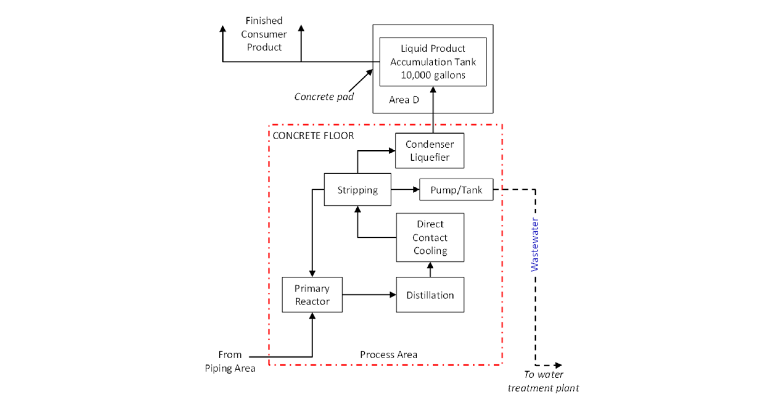
Figure 1: Example of a portion of a facility diagram showing how manufacturing equipment could be represented (note that more detailed diagrams would need to be available at the facility):
Highlights of Figure 1
Figure 1 demonstrates a simplified example of oil-filled equipment and piping that can be included in a larger complete facility diagram. Oil-filled manufacturing equipment may be represented by, for example, a box that identifies the equipment and its location or a simplified process flow diagram.
Figure 2: Example showing how a complex piping area could be represented within a facility diagram (note that more detailed diagrams would need to be available at the facility):

Highlights of Figure 2
Figure 2 also demonstrates a simplified example of piping that can be included in a larger complete facility diagram. For areas of complicated piping, which often include different types, numbers, and lengths of pipes, the facility diagram may show a simplified box labeled “piping” or show a single line that identifies the service (such as supply/return), as long as more detailed diagrams are available at the facility.
Three facility diagram examples
This section includes example facility diagrams (Figures 3, 4, and 5) for three fictitious SPCC-regulated facilities. They illustrate how certain containers and equipment could be represented on a facility diagram. Preparation of a facility diagram is a site-specific effort, and the level of detail and/or approach taken to prepare it will vary based on what is needed to adequately describe the configuration for any given facility.
The examples provided are not meant to indicate a specific amount of detail an EPA inspector will require for each SPCC-regulated facility. They merely illustrate the concepts discussed in this how-to guide. In addition to a diagram, each figure offers a callout with important “highlights” on the concepts that are illustrated.
Facility diagrams, like the other elements of an SPCC plan, must be prepared in accordance with good engineering practice or in accordance with accepted and sound industry practices and standards. They must be reviewed by the professional engineer (or owner/operator, in the case of a Tier II qualified facility) certifying the plan. Section 112.7(a)(3) requires the facility diagram to show, at a minimum:
- The location and contents of fixed oil containers;
- Mobile/portable container storage area locations;
- Completely buried storage tanks, including those that may otherwise be exempt from the rule; and
- Transfer stations (i.e., areas where oil is transferred) and connecting pipes, including exempt intra-facility gathering lines.
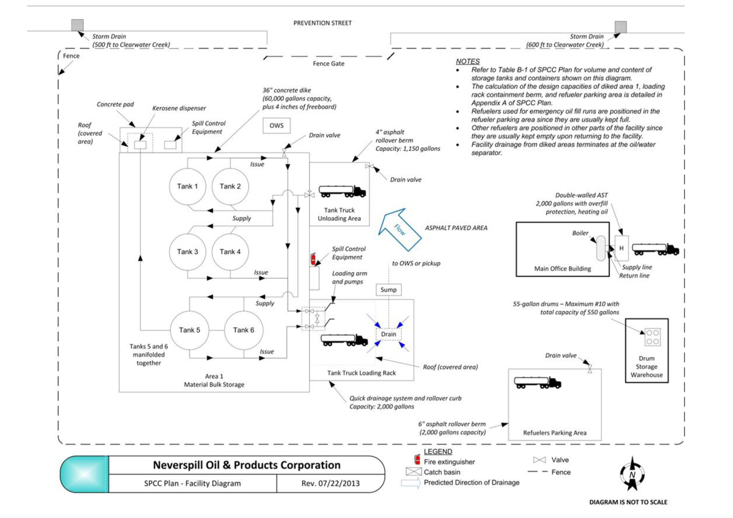
Figure 3: Example facility diagram, including a loading rack and a separate loading area:
Highlights of Figure 3
Figure 3 illustrates a diagram for a bulk storage and distribution facility, which has a tank farm, a loading rack, an unloading area, and other oil containers and oil-filled equipment. As required by 112.7(a)(3), this diagram includes all containers with an oil storage capacity of 55 gallons or greater. In addition to listing the contents directly on the diagram, the diagram provides a reference to a supplementary table that contains the volume and content of the storage tanks shown on the diagram (appended to the diagram as Table B-1).
At the discretion of the plan preparer who reviewed and certified the plan, the example facility diagram also depicts secondary containment methods and includes a reference to calculations for secondary containment capacity provided in other parts of the SPCC plan. Moreover, a separate log (Table B-2) identifies the contents of the drums in the storage warehouse and estimates the maximum number of containers.
Table B-1: Volume and contents of containers identified on the facility diagram (Figure 3):
| Tank/Container | Volume (gallons) | Contents |
|---|---|---|
| Area 1 | ||
| Tank 1 | 25,000 | Product A – #2 fuel oil |
| Tank 2 | 25,000 | Product A – #2 fuel oil |
| Tank 3 | 25,000 | Product B – #6 fuel oil |
| Tank 4 | 25,000 | Product B – #6 fuel oil |
| Tank 5 | 30,000 | Product C – Kerosene |
| Tank 6 | 30,000 | Product C – Kerosene |
| Main Office Building | ||
| Tank H | 2,000 | Heating oil |
| Drum Storage Warehouse | ||
| Up to 10 drums | 55 (each) | Various oil products (lubricating oil, engine oil, used oil, etc.) |
Table B-2: Drum storage warehouse log (maintained at the facility as part of inventory):
| Date | Number and Type of Container | Contents | Capacity | Location at Facility |
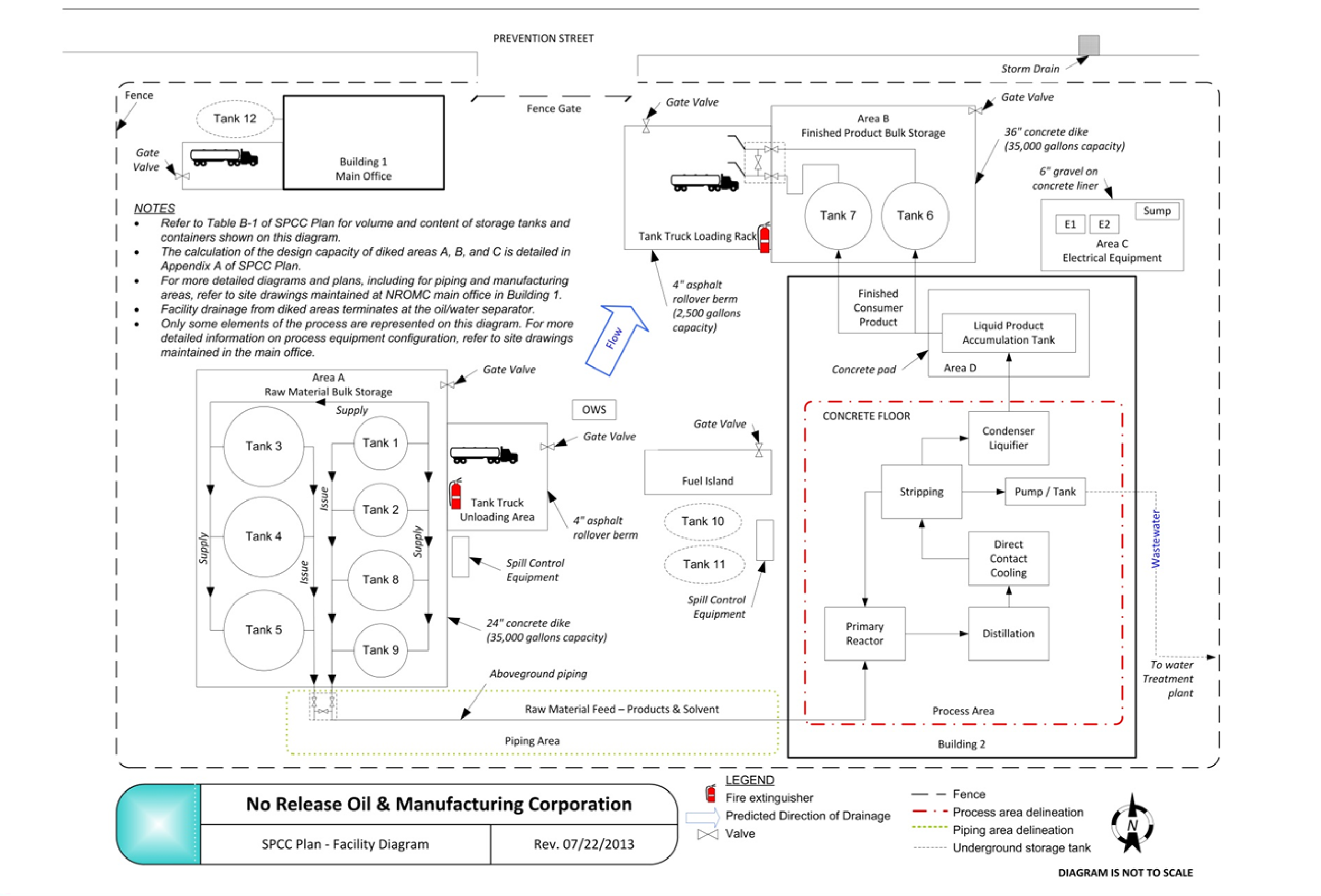
Figure 4: Example facility diagram, including oil-filled equipment, complex piping, and completely buried storage tanks:
Highlights of Figure 4
Figure 4 illustrates a large manufacturing facility with a variety of containers and equipment, including piping, oil-filled equipment (i.e., manufacturing equipment and transformers), and completely buried storage tanks. As required by 112.7(a)(3), this diagram includes all containers with a storage capacity of 55 gallons or greater. In addition to listing the contents directly on the diagram, the diagram includes a reference to a crosswalk that contains the volume and content of the storage containers shown on the diagram (appended to the diagram as Table B-3).
Additionally, the diagram notes the location and contents of completely buried storage tanks otherwise exempt from the SPCC rule because they meet all the technical requirements of 40 CFR 280 or an approved state UST program under 40 CFR 281 (in accordance with 112.7(a)(3)). While not an SPCC requirement, the diagram also marks the location of containers that store Clean Water Act hazardous substances and labels those containers.
This diagram also includes an example of how oil-filled manufacturing equipment and complex piping may be represented on a facility diagram, at the discretion of the owner/operator or professional engineer. The diagram references the more detailed diagrams and plans of the piping and manufacturing equipment that are available separately at the facility.
Finally, while not required in the diagram, this example also includes a reference to the calculation of diked storage provided in other parts of the SPCC plan and depicts wastewater treatment systems, secondary containment, and oil/water separators.
Table B-3: Volume and contents of containers identified on the facility diagram (Figure 4):
| Tank/Container | Volume (gallons) | Contents |
|---|---|---|
| Area A – Raw Material Bulk Storage | ||
| Tank 1 | 4,000 | Product A – #2 fuel oil |
| Tank 2 | 4,000 | Product A – #2 fuel oil |
| Tank 3 | 20,000 | Product B – #6 fuel oil |
| Tank 4 | 20,000 | Product B – #6 fuel oil |
| Tank 5 | 20,000 | Product B – #6 fuel oil |
| Tank 8 | 6,000 | Product C – Kerosene |
| Tank 9 | 4,000 | Solvent – Toluene |
| Area B – Finished Product Bulk Storage | ||
| Tank 6 | 20,000 | Product D – proprietary oil |
| Tank 7 | 20,000 | Product D – proprietary oil |
| Area C – Electrical Equipment | ||
| Transformer E1 | 235 | Silicon-based dielectric fluid |
| Transformer E2 | 235 | Silicon-based dielectric fluid |
| Area D | ||
| Liquid Product Accumulation Tank | 10,000 | Product D – proprietary oil |
| Process Area | ||
| Primary Reactor | 500 | Intermediate oil product |
| Distillation | 500 | Intermediate oil product |
| Direct Contact Cooling | 500 | Intermediate oil product |
| Stripping | 500 | Intermediate oil product |
| Pump/Tank | 300 | Intermediate oil product |
| Condenser Liquefier | 500 | Intermediate oil product |
| Underground Storage Tanks | ||
| Tank 10 (otherwise exempt from SPCC requirements) | 8,000 | Gasoline |
| Tank 11 (otherwise exempt from SPCC requirements) | 8,000 | Gasoline |
| Tank 12 | 2,000 | Heating oil |
Figure 5: Example facility diagram for an oil production facility:
Highlights of Figure 5
Figure 5 illustrates a small oil production facility with two extraction wells and a production tank battery. As required by 112.7(a)(3), this diagram includes all containers with a storage capacity of 55 gallons or greater and transfer areas. Because the facility has a relatively large footprint, the direction of flow is best displayed on a separate figure (Figure 6) that shows the general location of the site relative to receiving water bodies.
Figure 6: Example general facility location diagram for an oil production facility:
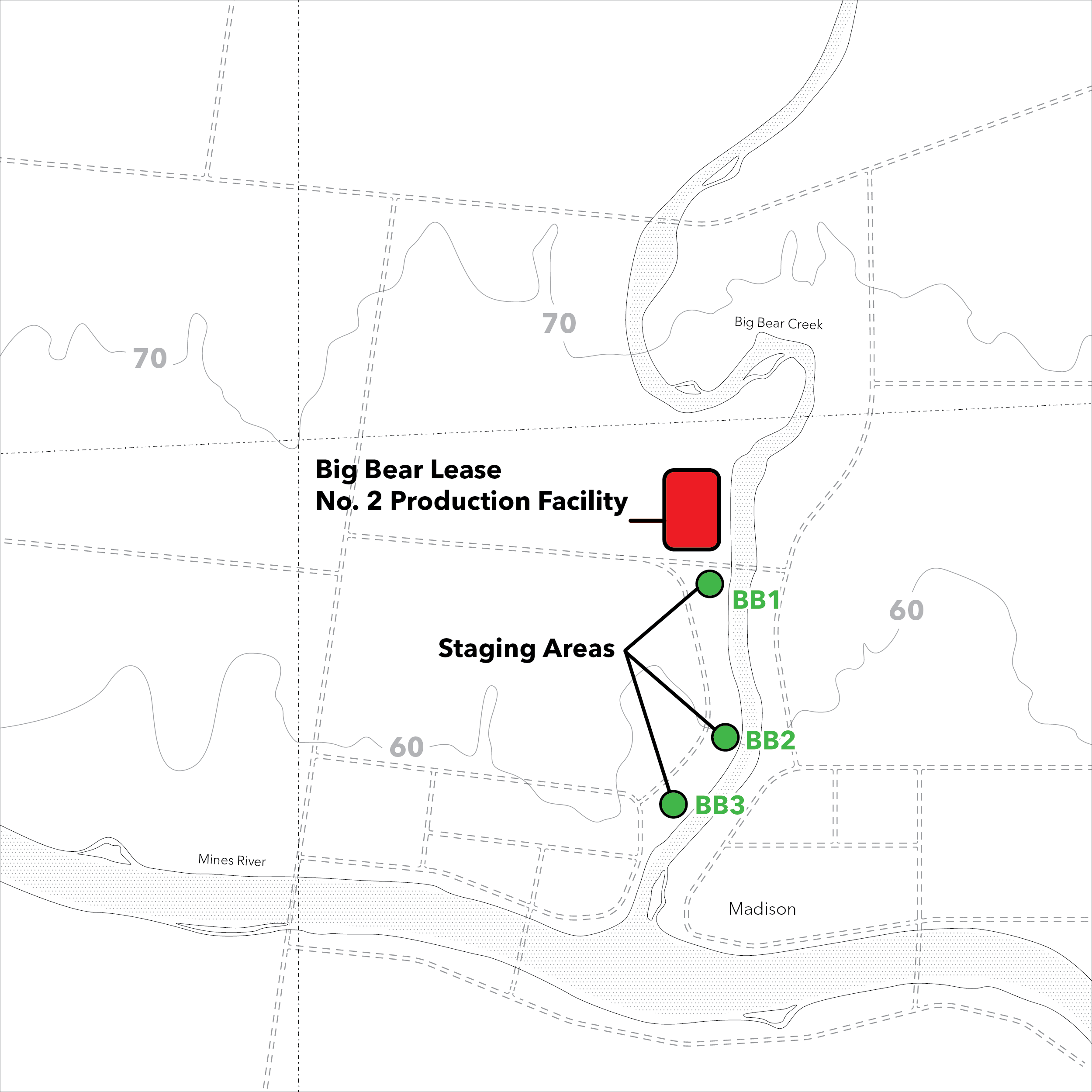
Highlights of Figure 6
Figure 6 helps to show the direction of flow and the general location of the site relative to receiving water bodies. Figure 6 is to be reviewed along with Figure 5, a more detailed view of the site. Figure 6 also shows three staging area locations and is supported by Table B-4, which indicates name, location, and contact information of the staging areas.
Table B-4: Staging area locations and contacts relating to facility location diagram (Figure 6):
| Staging area | Location | Contact Information |
|---|---|---|
| BB1 | 5540 Route 417, Madison, LA (access from path to the right of the storage shed). | Maurice Richard, (405) 830-2186 |
| BB2 | 6075 Greenfield Drive, Madison, LA | Jim Larouche, (405) 832-2645 |
| BB3 | 1644 Oilfield Road, Madison, LA | Peter Martin, (405) 832-5527 |
Facility diagram updates
If the facility itself has changed and is no longer accurately represented on the diagram, the supporting drawings for a simplified diagram are not available at the facility, or the diagram appears to be inadequate for the facility, appropriate follow-up action may be warranted. This action may include a request for more information or a plan amendment in accordance with 112.4(d).
Changes to the facility diagram are considered “administrative,” rather than “technical,” in nature and do not require professional engineer certification. The same is true for a Tier II qualified facility — the owner or operator does not need to certify changes to a facility diagram in accordance with 112.6(b)(2) because these changes are not considered technical amendments.
tank-systems
Tank Systems
tank-systems
Tank Systems
ENVIRONMENTAL EDGE
The facility diagram is an important and required component of an SPCC plan. It is used for prevention, planning, inspections, management, and response considerations. In most cases, the owner or operator of the facility will work with the professional engineer (PE) certifying the SPCC plan to identify the information to include on the facility diagram.
EPA regulation 40 CFR 112.7(a)(3) specifies the required elements of the diagram which applies to the owner and operator of a Tier II qualified facility or non-qualified facility. To be clear, Tier I qualified facilities are not required to prepare a facility diagram because EPA determined this type of facility is typically small and generally simple in configuration, and a facility diagram would not be needed to understand facility layout and locate areas of potential discharge at such a facility.
That means this how-to guide will help Tier II and non-qualified facility owners and operators prepare their own facility diagram for inclusion in their Tier II and full SPCC plan, respectively. This guide outlines the facility diagram requirements and recommendations and provides several diagram examples.
Purpose of the facility diagram
The facility diagram is not without purpose. According to EPA, it:
- Identifies the location and contents of each fixed oil storage container and location of mobile and portable container storage areas;
- May help responders avoid certain hazards by informing them of the location and content of containers and of the response equipment;
- May assist responders in determining the flow pathway of discharged oil and to take more effective measures to control the flow of oil to potentially avert damage to sensitive environmental areas; protect drinking water sources; and prevent discharges to other conduits, to a treatment facility, or to navigable waters or adjoining shorelines;
- Inform federal and state facility inspectors and facility personnel of the location of all containers, piping, and transfer areas subject to the SPCC rule;
- May be used to visually address other rule requirements such as discharge/drainage controls and the flow path of a discharge (112.7(a)(3)(iii) and 112.7(b), respectively); and
- May be attached to a facility inspection checklist to identify areas, containers, or equipment subject to inspection.
Avoiding duplication of efforts
EPA does not require that a facility diagram be developed exclusively for the SPCC plan. Some state and other federal regulations may already require a diagram with similar or overlapping requirements. States may supplement the SPCC minimum requirements with more stringent requirements. A facility diagram prepared for the following may be used in an SPCC plan if it meets the requirements of the SPCC rule:
- A state or other federal plan requirement, such as the Facility Response Plan (FRP) mandated by 112.20; or
- Other purposes, e.g., as-built plans, construction permits, facility modifications, and other pollution prevention requirements.
Similarly, facilities with oil-filled electrical equipment may base their facility diagrams on existing electrical one-line diagrams, provided the drawings are appended as necessary to include all of the containers, transfer areas, piping, and other information as required to meet 112.7(a)(3).
Required items on a facility diagram
The following items are required by 112.7(a)(3) to be illustrated in a facility diagram:
- Aboveground storage tanks, including location and contents;
- Underground storage tanks (USTs), including location and contents of USTs that are subject to the SPCC rule, as well as those that are exempt;
- Storage area(s) where mobile or portable containers are located;
- Transfer stations, such as oil transfer areas including loading/unloading racks and loading/unloading areas;
- Oil-filled equipment, such as hydraulic operating systems or manufacturing equipment (including location and contents);
- Oil-filled electrical transformers, circuit breakers, or other equipment (including location and contents);
- Connecting piping (if the scale of drawing permits);
- Oil pits or ponds (at oil production facilities);
- Oil production facility stock tanks, separation equipment, and produced water containers;
- Any other bulk storage or oil-filled operational equipment at an oil production facility; and
- Flowlines and intra-facility gathering lines at a production facility (this includes those that are subject to the SPCC rule and exempt intra-facility gathering lines subject to the requirements of 49 CFR 192 or 195 as described in 112.1(d)(11)).
Items exempted from a facility diagram
The following items are not required to be identified on the facility diagram:
- Containers that have a capacity of less than 55 gallons;
- Containers that are permanently closed;
- Containers that store Clean Water Act (CWA) hazardous substances listed in 40 CFR 116, Designation of Hazardous Substances; and
- Containers that are otherwise exempt from the SPCC rule (with the exception of exempt USTs and exempt intra-facility gathering lines).
Items EPA recommends (but does not require) in a facility diagram
In addition, EPA recommends (but does not require under the SPCC rule) that the following information be included on the facility diagram to maximize its utility for facility personnel, emergency responders, and inspectors:
- Aboveground storage tank capacities and/or tank identification numbers or letters;
- Containers that store CWA hazardous substances (listed in 40 CFR 116) and label the contents of these containers;
- Secondary containment structures, including oil/water separators used for containment;
- Storm drain inlets and surface waters that could be affected by a discharge;
- Direction of flow in the event of a discharge (which can serve to address the SPCC requirement under 112.7(b));
- Legend that indicates scale and identifies symbols used in the diagram;
- Location of response kits or other equipment used to implement an active containment strategy:
- Location of firefighting equipment and pipe stands for fire-retardant application;
- Location of valves or drainage system control that could be used in the event of a discharge to contain oil on the site; and
- Location of important piping appurtenances, such as valves, checks, or other piping-related equipment (to aid in facility response and inspection efforts);
- Compass direction indicating north; and
- Topographical information and area maps.
Level of detail for a facility diagram
As with other aspects of the SPCC plan, the facility diagram is to be prepared in accordance with “good engineering practice.” Thus, the level of detail provided and the approach taken for preparing an adequate facility diagram is primarily at the discretion of the person certifying the SPCC plan. Yet, the facility diagram should provide sufficient detail for the facility personnel to undertake prevention activities, for EPA to perform an effective inspection, and for responders to take effective measures.
EPA explains that the scale and level of detail shown on a facility diagram may vary, however, according to the needs and complexity of the facility. Owners or operators of a facility may represent complicated areas of piping or oil-filled equipment in a less-detailed manner on the facility diagram in the SPCC plan, as long as the information is contained in more detailed diagrams of the systems or is contained in some other form, and such information is maintained elsewhere at the facility and this location is referenced in the SPCC plan. For example, the diagram may merely indicate an area where complicated oil-filled equipment (such as manufacturing equipment) is located, and the plan would then provide a table describing the type(s) of equipment and contents of the oil storage containers.
What about specific containers and equipment on the facility diagram?
The following sections provide information on identifying certain container and equipment types on the facility diagram:
- Fixed storage containers — The location of all containers located in a fixed position must be on the diagram. However, if a diagram becomes complicated by multiple oil storage containers, the owner or operator may choose to include the contents of the containers separately in an accompanying table/key in the SPCC plan.
- Mobile or portable containers — The storage area(s) of mobile or portable containers must be marked on the diagram in their out-of-service or designated storage area(s), primary storage area(s), or area(s) where they are most frequently located. If containers are stored in one area and operated in another area, both “areas” would be identified on the diagram. These “areas” may be marked as general locations on the diagram rather than identifying specific discrete locations for each mobile or portable container. The general contents of each container may be noted on the diagram and more detailed content information provided separately (such as on a separate sheet, log, or electronic system). If the contents of a container change frequently, the contents may be recorded separately, or on the diagram, and if the information is provided separately, the diagram should note that contents vary.
- Underground storage tanks — A facility diagram must include the location and contents of all USTs that are subject to SPCC requirements, as well as USTs that are exempt from SPCC requirements. SPCC-exempted USTs must also be marked “exempt” on the facility diagram.
- Intra-facility gathering lines — The facility diagram must include all transfer stations (i.e., any location where oil is transferred) and connecting pipes, including intra-facility gathering lines that are otherwise exempted from SPCC requirements. Although the SPCC rule exempts those intra-facility gathering lines that are subject to the regulatory requirements of 49 CFR 192 or 195, their location must be identified and marked as “exempt” on the facility diagram.
- Piping and oil-filled equipment — Oil-filled equipment (such as manufacturing equipment) and associated piping present at an SPCC-regulated facility may be difficult to represent on a facility diagram, due to their relative location, complexity, or design. Therefore, an owner/operator may represent such systems in a “less detailed” manner on the facility diagram, as long as more “detailed” drawings are maintained at the facility and referenced in the SPCC plan. More detailed drawings may include blueprints, engineering diagrams, or diagrams developed to comply with other local, state, or federal requirements. In addition, EPA explains that schematic representations that provide a general overview of the piping service (e.g., supply/return) may provide sufficient information when combined with a description of the piping in the SPCC plan. Alternatively, overlay diagrams showing different portions of the piping system may be used where the density and/or complexity of the piping system would make a single diagram difficult to read. Although the SPCC rule requires that piping be included on the facility diagram, it is not necessary to include appurtenances associated with the piping. See Figures 1 and 2.
Figure 1: Example of a portion of a facility diagram showing how manufacturing equipment could be represented (note that more detailed diagrams would need to be available at the facility):
Highlights of Figure 1
Figure 1 demonstrates a simplified example of oil-filled equipment and piping that can be included in a larger complete facility diagram. Oil-filled manufacturing equipment may be represented by, for example, a box that identifies the equipment and its location or a simplified process flow diagram.
Figure 2: Example showing how a complex piping area could be represented within a facility diagram (note that more detailed diagrams would need to be available at the facility):
Highlights of Figure 2
Figure 2 also demonstrates a simplified example of piping that can be included in a larger complete facility diagram. For areas of complicated piping, which often include different types, numbers, and lengths of pipes, the facility diagram may show a simplified box labeled “piping” or show a single line that identifies the service (such as supply/return), as long as more detailed diagrams are available at the facility.
Three facility diagram examples
This section includes example facility diagrams (Figures 3, 4, and 5) for three fictitious SPCC-regulated facilities. They illustrate how certain containers and equipment could be represented on a facility diagram. Preparation of a facility diagram is a site-specific effort, and the level of detail and/or approach taken to prepare it will vary based on what is needed to adequately describe the configuration for any given facility.
The examples provided are not meant to indicate a specific amount of detail an EPA inspector will require for each SPCC-regulated facility. They merely illustrate the concepts discussed in this how-to guide. In addition to a diagram, each figure offers a callout with important “highlights” on the concepts that are illustrated.
Facility diagrams, like the other elements of an SPCC plan, must be prepared in accordance with good engineering practice or in accordance with accepted and sound industry practices and standards. They must be reviewed by the professional engineer (or owner/operator, in the case of a Tier II qualified facility) certifying the plan. Section 112.7(a)(3) requires the facility diagram to show, at a minimum:
- The location and contents of fixed oil containers;
- Mobile/portable container storage area locations;
- Completely buried storage tanks, including those that may otherwise be exempt from the rule; and
- Transfer stations (i.e., areas where oil is transferred) and connecting pipes, including exempt intra-facility gathering lines.
Figure 3: Example facility diagram, including a loading rack and a separate loading area:
Highlights of Figure 3
Figure 3 illustrates a diagram for a bulk storage and distribution facility, which has a tank farm, a loading rack, an unloading area, and other oil containers and oil-filled equipment. As required by 112.7(a)(3), this diagram includes all containers with an oil storage capacity of 55 gallons or greater. In addition to listing the contents directly on the diagram, the diagram provides a reference to a supplementary table that contains the volume and content of the storage tanks shown on the diagram (appended to the diagram as Table B-1).
At the discretion of the plan preparer who reviewed and certified the plan, the example facility diagram also depicts secondary containment methods and includes a reference to calculations for secondary containment capacity provided in other parts of the SPCC plan. Moreover, a separate log (Table B-2) identifies the contents of the drums in the storage warehouse and estimates the maximum number of containers.
Table B-1: Volume and contents of containers identified on the facility diagram (Figure 3):
| Tank/Container | Volume (gallons) | Contents |
|---|---|---|
| Area 1 | ||
| Tank 1 | 25,000 | Product A – #2 fuel oil |
| Tank 2 | 25,000 | Product A – #2 fuel oil |
| Tank 3 | 25,000 | Product B – #6 fuel oil |
| Tank 4 | 25,000 | Product B – #6 fuel oil |
| Tank 5 | 30,000 | Product C – Kerosene |
| Tank 6 | 30,000 | Product C – Kerosene |
| Main Office Building | ||
| Tank H | 2,000 | Heating oil |
| Drum Storage Warehouse | ||
| Up to 10 drums | 55 (each) | Various oil products (lubricating oil, engine oil, used oil, etc.) |
Table B-2: Drum storage warehouse log (maintained at the facility as part of inventory):
| Date | Number and Type of Container | Contents | Capacity | Location at Facility |
Figure 4: Example facility diagram, including oil-filled equipment, complex piping, and completely buried storage tanks:
Highlights of Figure 4
Figure 4 illustrates a large manufacturing facility with a variety of containers and equipment, including piping, oil-filled equipment (i.e., manufacturing equipment and transformers), and completely buried storage tanks. As required by 112.7(a)(3), this diagram includes all containers with a storage capacity of 55 gallons or greater. In addition to listing the contents directly on the diagram, the diagram includes a reference to a crosswalk that contains the volume and content of the storage containers shown on the diagram (appended to the diagram as Table B-3).
Additionally, the diagram notes the location and contents of completely buried storage tanks otherwise exempt from the SPCC rule because they meet all the technical requirements of 40 CFR 280 or an approved state UST program under 40 CFR 281 (in accordance with 112.7(a)(3)). While not an SPCC requirement, the diagram also marks the location of containers that store Clean Water Act hazardous substances and labels those containers.
This diagram also includes an example of how oil-filled manufacturing equipment and complex piping may be represented on a facility diagram, at the discretion of the owner/operator or professional engineer. The diagram references the more detailed diagrams and plans of the piping and manufacturing equipment that are available separately at the facility.
Finally, while not required in the diagram, this example also includes a reference to the calculation of diked storage provided in other parts of the SPCC plan and depicts wastewater treatment systems, secondary containment, and oil/water separators.
Table B-3: Volume and contents of containers identified on the facility diagram (Figure 4):
| Tank/Container | Volume (gallons) | Contents |
|---|---|---|
| Area A – Raw Material Bulk Storage | ||
| Tank 1 | 4,000 | Product A – #2 fuel oil |
| Tank 2 | 4,000 | Product A – #2 fuel oil |
| Tank 3 | 20,000 | Product B – #6 fuel oil |
| Tank 4 | 20,000 | Product B – #6 fuel oil |
| Tank 5 | 20,000 | Product B – #6 fuel oil |
| Tank 8 | 6,000 | Product C – Kerosene |
| Tank 9 | 4,000 | Solvent – Toluene |
| Area B – Finished Product Bulk Storage | ||
| Tank 6 | 20,000 | Product D – proprietary oil |
| Tank 7 | 20,000 | Product D – proprietary oil |
| Area C – Electrical Equipment | ||
| Transformer E1 | 235 | Silicon-based dielectric fluid |
| Transformer E2 | 235 | Silicon-based dielectric fluid |
| Area D | ||
| Liquid Product Accumulation Tank | 10,000 | Product D – proprietary oil |
| Process Area | ||
| Primary Reactor | 500 | Intermediate oil product |
| Distillation | 500 | Intermediate oil product |
| Direct Contact Cooling | 500 | Intermediate oil product |
| Stripping | 500 | Intermediate oil product |
| Pump/Tank | 300 | Intermediate oil product |
| Condenser Liquefier | 500 | Intermediate oil product |
| Underground Storage Tanks | ||
| Tank 10 (otherwise exempt from SPCC requirements) | 8,000 | Gasoline |
| Tank 11 (otherwise exempt from SPCC requirements) | 8,000 | Gasoline |
| Tank 12 | 2,000 | Heating oil |
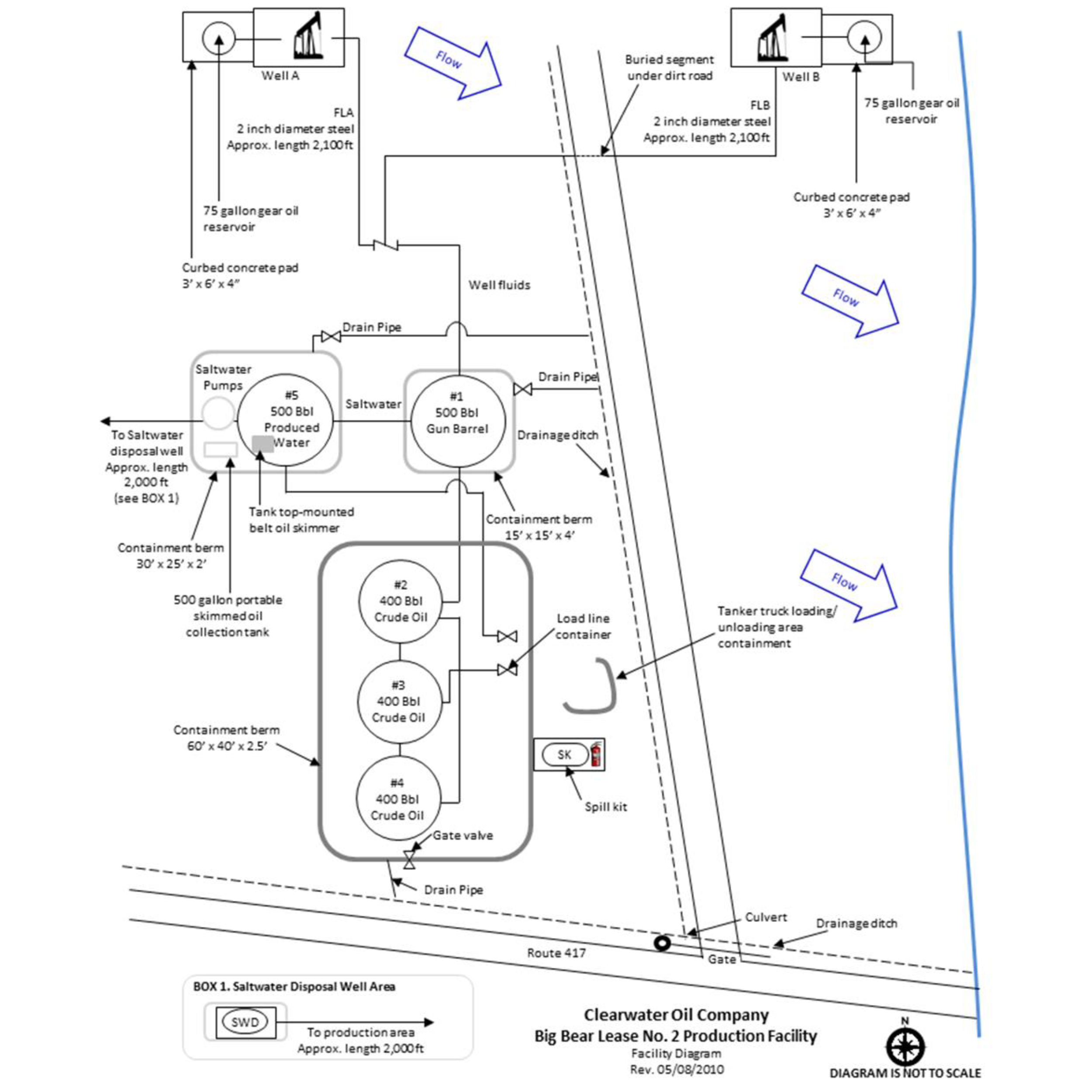
Figure 5: Example facility diagram for an oil production facility:
Highlights of Figure 5
Figure 5 illustrates a small oil production facility with two extraction wells and a production tank battery. As required by 112.7(a)(3), this diagram includes all containers with a storage capacity of 55 gallons or greater and transfer areas. Because the facility has a relatively large footprint, the direction of flow is best displayed on a separate figure (Figure 6) that shows the general location of the site relative to receiving water bodies.
Figure 6: Example general facility location diagram for an oil production facility:
Highlights of Figure 6
Figure 6 helps to show the direction of flow and the general location of the site relative to receiving water bodies. Figure 6 is to be reviewed along with Figure 5, a more detailed view of the site. Figure 6 also shows three staging area locations and is supported by Table B-4, which indicates name, location, and contact information of the staging areas.
Table B-4: Staging area locations and contacts relating to facility location diagram (Figure 6):
| Staging area | Location | Contact Information |
|---|---|---|
| BB1 | 5540 Route 417, Madison, LA (access from path to the right of the storage shed). | Maurice Richard, (405) 830-2186 |
| BB2 | 6075 Greenfield Drive, Madison, LA | Jim Larouche, (405) 832-2645 |
| BB3 | 1644 Oilfield Road, Madison, LA | Peter Martin, (405) 832-5527 |
Facility diagram updates
If the facility itself has changed and is no longer accurately represented on the diagram, the supporting drawings for a simplified diagram are not available at the facility, or the diagram appears to be inadequate for the facility, appropriate follow-up action may be warranted. This action may include a request for more information or a plan amendment in accordance with 112.4(d).
Changes to the facility diagram are considered “administrative,” rather than “technical,” in nature and do not require professional engineer certification. The same is true for a Tier II qualified facility — the owner or operator does not need to certify changes to a facility diagram in accordance with 112.6(b)(2) because these changes are not considered technical amendments.
Answer
UPGRADE TO CONTINUE READING