
...
(a) Gas well liquids unloading standards for well designated facility. For each well liquids unloading operation at your well designated facility, you must demonstrate continuous compliance with the requirements of §60.5390c by submitting the annual report information specified in §60.5420c(b)(1) and (2) and maintaining the records for each well liquids unloading event that vents to the atmosphere as specified in §60.5420c(c)(1). For each gas well liquids unloading well affected facility that complies with the requirements of §60.5390c(g), you must route emissions to a control device through a closed vent system and continuously comply with the closed vent requirements of §60.5416c. You also must comply with the requirements specified in paragraph (f) of this section and maintain the records in §60.5420c(c)(7), (9) and (11).
(b) Associated gas well standards for well designated facility. For each associated gas well at your well designated facility, you must demonstrate continuous compliance with the requirements of §60.5391c by submitting the reports required by §60.5420c(b)(1) and (3) and maintaining the records specified in §60.5420c(c)(2). For each associated gas well at your well designated facility that complies with the requirements of §60.5391c(b) or (c), you must route emissions to a control device through a closed vent system and continuously comply with the closed vent requirements of §60.5416c. You must also comply with the requirements specified in paragraph (e) of this section and maintain the records in paragraphs (c)(7), (9) and (11) of this section.
(c) Centrifugal compressor designated facility. For each centrifugal compressor designated facility complying with the volumetric flow rate measurements requirements in §60.5392c(a)(1) and (2), you must demonstrate continuous compliance according to paragraph (c)(1) and paragraphs (c)(3) and (4) of this section. Alternatively, for each wet seal and dry seal centrifugal compressor designated facility complying with §60.5392c(a)(3) and (a)(4) or (5) by routing emissions to a control device or to a process, you must demonstrate continuous compliance according to paragraphs (c)(2) through (4) of this section.
(1) You must maintain volumetric flow rate at or below the volumetric flow rates specified in paragraphs (c)(1)(i) through (iii) of this section for your centrifugal compressor, as applicable, and you must conduct the required volumetric flow rate measurement of your dry or wet seal in accordance with §60.5392c(a)(1) and (2) on or before 8,760 hours of operation after your last volumetric flow rate measurement which demonstrates compliance with the applicable volumetric flow rate.
(i) For your wet seal centrifugal compressors (including self-contained wet seal centrifugal compressors), you must maintain the volumetric flow rate at or below 3 scfm per seal (or in the case of manifolded groups of seals, 3 scfm multiplied by the number of seals).
(ii) For your Alaska North Slope centrifugal compressor equipped with sour seal oil separator and capture system, you must maintain the volumetric flow rate at or below 9 scfm per seal (or in the case of manifolded groups of wet seals, 9 scfm multiplied by the number of seals).
(iii) For your dry seal compressor, you must maintain the volumetric flow rate at or below 10 scfm per seal (or in the case of manifolded groups of wet seals, 10 scfm multiplied by the number of seals).
(2) For each wet seal and dry seal centrifugal compressor designated facility complying by routing emissions to a control device or to a process, you must operate the wet seal emissions collection system and dry seal system to route emissions to a control device or a process through a closed vent system and continuously comply with the closed vent requirements of §60.5416c(a) and (b). If you comply with §60.5392c(a)(4) by using a control device, you also must comply with the requirements in paragraph (e) of this section.
(3) You must submit the annual reports as required in §60.5420c(b)(1), (4) and (10)(i) through (iv), as applicable.
(4) You must maintain records as required in §60.5420c(c)(3), (7) through (9) and (11), as applicable.
(d) Pump designated facility. To demonstrate continuous compliance with the GHG standards for your pump designated facility as required by §60.5395c, you must comply with paragraphs (d)(1) through (3) of this section.
(1) For pump designated facilities complying with the requirements of §60.5395c(a) by routing emissions to a process and for pump designated facilities complying with the requirements of §60.5395c(b)(1) or (3), you must continuously comply with the closed vent requirements of §60.5416c(a) and (b). If you comply with §60.5395c(b)(3), you also must comply with the requirements in paragraph (d) of this section.
(2) You must submit the annual reports for your pump designated facility as required in §60.5420c(b)(1), and (9) through (12), as applicable.
(3) You must maintain the records for your pump designated facility as specified in §60.5420c(c)(14), as applicable.
(e) Additional continuous compliance requirements for well, centrifugal compressor, reciprocating compressor, process controllers in Alaska, storage vessel, process unit equipment, or pump designated facilities. For each associated gas well at your well designated facility, each gas well liquids unloading operation at your well designated facility, each centrifugal compressor designated facility, each reciprocating compressor designated facility, each process controller designated facility in Alaska, each storage vessel designated facility, each process unit equipment designated facility, and each pump designated facility referenced to this paragraph from either paragraph (a), (b), (c)(2), (d)(1), (f), (g)(2)(iv), (h) or (i) of this section, you must also install monitoring systems as specified in §60.5417c, demonstrate continuous compliance according to paragraph (e)(1) of this section, maintain the records in paragraph (e)(2) of this section, and comply with the reporting requirements specified in paragraph (e)(3) of this section.
(1) You must demonstrate continuous compliance with the control device performance requirements of §60.5412c(a) using the procedures specified in paragraphs (e)(1)(i) through (viii) of this section and conducting the monitoring as required by §60.5417c. If you use a condenser as the control device to achieve the requirements specified in §60.5412c(a)(2), you may demonstrate compliance according to paragraph (e)(1)(ix) of this section. You may switch between compliance with paragraphs (e)(1)(i) through (viii) of this section and compliance with paragraph (e)(1)(ix) of this section only after at least 1 year of operation in compliance with the selected approach. You must provide notification of such a change in the compliance method in the next annual report, following the change. If you use an enclosed combustion device or a flare as the control device, you must also conduct the monitoring required in paragraph (e)(1)(x) of this section. If you use an enclosed combustion device or flare using an alternative test method approved under §60.5412c(d), you must use the procedures in paragraph (e)(1)(xi) of this section in lieu of the procedures in paragraphs (e)(1)(i) through (viii) of this section, but you must still conduct the monitoring required in paragraph (e)(1)(x) of this section.
(i) You must operate below (or above) the site-specific maximum (or minimum) parameter value established according to the requirements of §60.5417c(f)(1). For flares, you must operate above the limits specified in paragraphs (e)(1)(vii)(B) of this section.
(ii) You must calculate the average of the applicable monitored parameter in accordance with §60.5417c(e).
(iii) Compliance with the operating parameter limit is achieved when the average of the monitoring parameter value calculated under paragraph (e)(1)(ii) of this section is either equal to or greater than the minimum parameter value or equal to or less than the maximum parameter value established under paragraph (e)(1)(i) of this section. When performance testing of a combustion control device is conducted by the device manufacturer as specified in §60.5413c(d), compliance with the operating parameter limit is achieved when the criteria in §60.5413c(e) are met.
(iv) You must operate the continuous monitoring system required in §60.5417c(a) at all times the affected source is operating, except for periods of monitoring system malfunctions, repairs associated with monitoring system malfunctions and required monitoring system quality assurance or quality control activities (including, as applicable, system accuracy audits and required zero and span adjustments). A monitoring system malfunction is any sudden, infrequent, not reasonably preventable failure of the monitoring system to provide valid data. Monitoring system failures that are caused in part by poor maintenance or careless operation are not malfunctions. You are required to complete monitoring system repairs in response to monitoring system malfunctions and to return the monitoring system to operation as expeditiously as practicable.
(v) You may not use data recorded during monitoring system malfunctions, repairs associated with monitoring system malfunctions, or required monitoring system quality assurance or control activities in calculations used to report emissions or operating levels. You must use all the data collected during all other required data collection periods to assess the operation of the control device and associated control system.
(vi) Failure to collect required data is a deviation of the monitoring requirements.
(vii) If you use an enclosed combustion device to meet the requirements of §60.5412c(a)(1) and you demonstrate compliance using the test procedures specified in §60.5413c(b), or you use a flare designed and operated in accordance with §60.5412c(a)(3), you must comply with the applicable requirements in paragraphs (e)(1)(vii)(A) through (E) of this section.
(A) For each enclosed combustion device which is not a catalytic vapor incinerator and for each flare, you must comply with the requirements in paragraphs (e)(1)(vii)(A)(1) through (4) of this section.
(1) A pilot or combustion flame must be present at all times of operation. An alert must be sent to the nearest control room whenever the pilot or combustion flame is unlit.
(2) Devices must be operated with no visible emissions, except for periods not to exceed a total of 1 minute during any 15-minute period. A visible emissions test conducted according to section 11 of Method 22 of appendix A–7 to this part, must be performed at least once every calendar month, separated by at least 15 days between each test. The observation period shall be 15 minutes or once the amount of time visible emissions is present has exceeded 1 minute, whichever time period is less. Alternatively, you may conduct visible emissions monitoring according to §60.5417c(h).
(3) Devices failing the visible emissions test must follow manufacturer's repair instructions, if available, or best combustion engineering practice as outlined in the unit inspection and maintenance plan, to return the unit to compliant operation. All repairs and maintenance activities for each unit must be recorded in a maintenance and repair log and must be available for inspection.
(4) Following return to operation from maintenance or repair activity, each device must pass a Method 22 of appendix A–7 to this part visual observation as described in paragraph (e)(1)(vii)(D) of this section or be monitored according to §60.5417c(h).
(B) For flares, you must comply with the requirements in paragraphs (e)(1)(vii)(B)(1) through (6) of this section.
(1) For unassisted flares, maintain the NHV of the gas sent to the flare at or above 200 Btu/scf.
(2) If you use a pressure assisted flare, maintain the NHV of gas sent to the flare at or above 800 Btu/scf.
(3) For steam-assisted and air-assisted flares, maintain the NHV cz at or above 270 Btu/scf.
(4) For flares with perimeter assist air, maintain the NHV dil at or above 22 Btu/sqft. If the only assist air provided to the flare is perimeter assist air intentionally entrained in lower and/or upper steam at the flare tip and the effective diameter is 9 inches or greater, you are not required to comply with the NHV dil limit.
(5) Unless you use a pressure-assisted flare, maintain the flare tip velocity below the applicable limits in §60.18(b).
(6) Maintain the total gas flow to the flare above the minimum inlet gas flow rate. The minimum inlet gas flow rate is established based on manufacturer recommendations.
(C) For enclosed combustion devices for which, during the performance test conducted under §60.5413c(b), the combustion zone temperature is not an indicator of destruction efficiency, you must comply with the requirements in paragraphs (e)(1)(vii)(C)(1) through (5) of this section, as applicable.
(1) Maintain the total gas flow to the enclosed combustion device at or above the minimum inlet gas flow rate and at or below the maximum inlet flow rate for the enclosed combustion device established in accordance with §60.5417c(f).
(2) For unassisted enclosed combustion devices, maintain the NHV of the gas sent to the enclosed combustion device at or above 200 Btu/scf.
(3) For enclosed combustion devices that use pressure-assisted burner tips to promote mixing at the burner tip, maintain the NHV of the gas sent to the enclosed combustion device at or above 800 Btu/scf.
(4) For steam-assisted and air-assisted enclosed combustion devices, maintain the NHV cz at or above 270 Btu/scf.
(5) For enclosed combustion devices with perimeter assist air, maintain the NHV dil at or above 22 Btu/sqft. If the only assist air provided to the enclosed combustion device is perimeter assist air intentionally entrained in lower and/or upper steam at the flare tip and the effective diameter is 9 inches or greater, you are not required to comply with the NHV dil limit.
(D) For enclosed combustion devices for which, during the performance test conducted under §60.5413c(b), the combustion zone temperature is demonstrated to be an indicator of destruction efficiency, you must comply with the requirements in paragraphs (e)(1)(vii)(D)(1) and (2) of this section.
(1) Maintain the temperature at or above the minimum temperature established during the most recent performance test. The minimum temperature limit established during the most recent performance test is the average temperature recorded during each test run, averaged across the 3 test runs (average of the test run averages).
(2) Maintain the total gas flow to the enclosed combustion device at or above the minimum inlet gas flow rate and at or below the maximum inlet flow rate for the enclosed combustion device established in accordance with §60.5417c(f).
(E) For catalytic vapor incinerators you must operate the catalytic vapor incinerator at or above the minimum temperature of the catalyst bed inlet and at or above the minimum temperature differential between the catalyst bed inlet and the catalyst bed outlet established in accordance with §60.5417c(f).
(viii) If you use a carbon adsorption system as the control device to meet the requirements of §60.5412c(a)(2), you must demonstrate compliance by the procedures in paragraphs (e)(1)(viii)(A) and (B) of this section, as applicable.
(A) If you use a regenerative-type carbon adsorption system, you must comply with paragraphs (e)(1)(viii)(A)(1) through (4) of this section.
(1) You must maintain the average regenerative mass flow or volumetric flow to the carbon adsorber during each bed regeneration cycle above the limit established in in accordance with §60.5413c(c)(2).
(2) You must maintain the average carbon bed temperature above the temperature limit established in accordance with §60.5413c(c)(2) during the carbon bed steaming cycle and below the carbon bed temperature established in in accordance with §60.5413c(c)(2) after the regeneration cycle.
(3) You must check the mechanical connections for leakage at least every month, and you must perform a visual inspection at least every 3 months of all components of the continuous parameter monitoring system for physical and operational integrity and all electrical connections for oxidation and galvanic corrosion if your continuous parameter monitoring system is not equipped with a redundant flow sensor.
(4) You must replace all carbon in the carbon adsorption system with fresh carbon on a regular, predetermined time interval that is no longer than the carbon service life established according to §60.5413c(c)(2).
(B) If you use a nonregenerative-type carbon adsorption system, you must replace all carbon in the control device with fresh carbon on a regular, predetermined time interval that is no longer than the carbon service life established according to §60.5413c(c)(3).
(ix) If you use a condenser as the control device to achieve the percent reduction performance requirements specified in §60.5412c(a)(2), you must demonstrate compliance using the procedures in paragraphs (e)(1)(ix)(A) through (E) of this section.
(A) You must establish a site-specific condenser performance curve according to §60.5417c(f)(2).
(B) You must calculate the daily average condenser outlet temperature in accordance with §60.5417c(e).
(C) You must determine the condenser efficiency for the current operating day using the daily average condenser outlet temperature calculated under paragraph (e)(1)(ix)(B) of this section and the condenser performance curve established under paragraph (e)(1)(ix)(A) of this section.
(D) Except as provided in paragraphs (e)(1)(ix)(D)(1) and (2) of this section, at the end of each operating day, you must calculate the 365-day rolling average TOC emission reduction, as appropriate, from the condenser efficiencies as determined in paragraph (e)(1)(ix)(C) of this section.
(1) After the compliance dates specified in §60.5387c(a), if you have less than 120 days of data for determining average TOC emission reduction, you must calculate the average TOC emission reduction for the first 120 days of operation after the compliance date. You have demonstrated compliance with the overall 95.0 percent reduction requirement if the 120-day average TOC emission reduction is equal to or greater than 95.0 percent.
(2) After 120 days and no more than 364 days of operation after the compliance date specified in §60.5387c(a), you must calculate the average TOC emission reduction as the TOC emission reduction averaged over the number of days between the current day and the applicable compliance date. You have demonstrated compliance with the overall 95.0 percent reduction requirement if the average TOC emission reduction is equal to or greater than 95.0 percent.
(E) If you have data for 365 days or more of operation, you have demonstrated compliance with the TOC emission reduction if the rolling 365-day average TOC emission reduction calculated in paragraph (e)(1)(ix)(D) of this section is equal to or greater than 95.0 percent.
(x) During each inspection conducted using an OGI camera under §60.5397c and during each periodic screening event or each inspection conducted using an OGI camera under §60.5398c, you must observe each enclosed combustion device and flare to determine if it is operating properly. You must determine whether there is a flame present and whether any uncontrolled emissions from the control device are visible with the OGI camera or the technique used to conduct the periodic screening event. During each inspection conducted under §60.5397c using AVO, you must observe each enclosed combustion device and flare to determine if it is operating properly. Visually confirm that the pilot or combustion flame is lit and that the pilot or combustion flame is operating properly.
(xi) If you use an enclosed combustion device or flare using an alternative test method approved under §60.5412c(d), you must comply with paragraphs (e)(1)(xi)(A) through (E) of this section.
(A) You must maintain the combustion efficiency at or above 95.0 percent. Alternatively, if the alternative test method does not directly monitor combustion efficiency, you must comply with the applicable requirements in paragraphs (e)(1)(xi)(A)(1) and (2) of this section.
(1) Maintain the NHV cz at or above 270 Btu/scf.
(2) For flares or enclosed combustion devices with perimeter assist air, maintain the NHV dil at or above 22 Btu/sqft. If the only assist air provided to the flare or enclosed combustion device is perimeter assist air intentionally entrained in lower and/or upper steam at the flare tip and the effective diameter is 9 inches or greater, you are only required to comply with the NHV cz limit specified in paragraph (e)(1)(xi)(A)(1) of this section.
(B) You must calculate the value of the applicable monitored metric(s) in accordance with the approved alternative test method. Compliance with the limit is achieved when the calculated values are within the range specified in paragraph (e)(1)(xi)(A) of this section.
(C) You must conduct monitoring using the alternative test method at all times the affected source is operating, except for periods of monitoring system malfunctions, repairs associated with monitoring system malfunctions and required monitoring system quality assurance or quality control activities (including, as applicable, system accuracy audits and required zero and span adjustments). A monitoring system malfunction is any sudden, infrequent, not reasonably preventable failure of the monitoring system to provide valid data. Monitoring system failures that are caused in part by poor maintenance or careless operation are not malfunctions. You are required to complete monitoring system repairs in response to monitoring system malfunctions and to return the monitoring system to operation as expeditiously as practicable.
(D) You may not use data recorded during monitoring system malfunctions, repairs associated with monitoring system malfunctions, or required monitoring system quality assurance or control activities in calculations used to report values to demonstrate compliance with the limits specified in paragraph (e)(1)(xi)(A) of this section. You must use all the data collected during all other required data collection periods to assess the operation of the control device and associated control system.
(E) Failure to collect required data is a deviation of the monitoring requirements.
(2) You must maintain the records as specified in §60.5420c(c)(10) and (12).
(3) You must comply with the reporting requirements in §60.5420c(b)(10) through (12).
(f) Reciprocating compressor designated facility. For each reciprocating compressor designated facility complying with §60.5393c(a) through (c), you must demonstrate continuous compliance according to paragraphs (f)(1), (3) and (4) of this section. For each reciprocating compressor designated facility complying with §60.5393c(d), you must demonstrate continuous compliance according to paragraph (f)(4) through (6) of this section. For each reciprocating compressor affected facility complying with §60.5393c(d)(2), you must demonstrate continuous compliance according to paragraphs (g)(3) through (6) of this section.
(1) You must maintain the volumetric flow rate at or below 2 scfm per cylinder (or at or below the combined volumetric flow rate determined by multiplying the number of cylinders by 2 scfm), and you must conduct the required volumetric flow rate measurement of your reciprocating compressor rod packing vents in accordance with §60.5393c(b) on or before 8,760 hours of operation after your last volumetric flow rate measurement which demonstrated compliance with the applicable volumetric flow rate.
(2) You must operate the rod packing emissions collection system to route emissions to a control device or to a process through a closed vent system and continuously comply with the cover and closed vent requirements of §60.5416c. If you comply with §60.5393c(d) by using a control device, you also must comply with the requirements in paragraph (e) of this section.
(3) You must continuously monitor the number of hours of operation for each reciprocating compressor affected facility since initial startup, since 60 days after the state plan submittal deadline (as specified in §60.5362c(c)), since the previous flow rate measurement, or since the date of the most recent reciprocating compressor rod packing replacement, whichever date is latest.
(4) You must replace the reciprocating compressor rod packing on or before the total number of hours of operation reaches 8,760 hours.
(5) You must submit the annual reports as required in §60.5420c(b)(1), (5), and (b)(10)(i) through (iv), as applicable.
(6) You must maintain records as required in §60.5420c(c)(4), (7), (9), and (11), as applicable.
(g) Process controller designated facility. To demonstrate continuous compliance with GHG emission standards for your process controller designated facility as required by §60.5394c, you must comply with the paragraphs (g)(1) through (4) of this section.
(1) You must demonstrate that your process controller designated facility does not emit any methane to the atmosphere by meeting the requirements of paragraphs (g)(1)(i) or (ii) of this section.
(i) If you comply by routing the emissions to a process, you must comply with the closed vent system inspection and monitoring requirements of §60.5416c.
(ii) If you comply by using a self-contained natural gas-driven process controller, you must conduct the no identifiable emissions inspections required by §60.5416c(b).
(2) For each process controller designated facility located at a site in Alaska that does not have access to electrical power, and that complies by reducing methane emissions from all controllers in the process controller designated facility by 95.0 percent in accordance with §60.5494c(b)(3), you must comply with comply with the closed vent requirements of §60.5416c and the requirements in paragraph (f) of this section for the control device.
(3) You must submit the annual report for your process controller as required in §60.5420c(b)(1), (6), and (10) through (12), as applicable.
(4) You must maintain the records as specified in §60.5420c(c)(5) for each process controller designated facility, as applicable.
(h) Storage vessel designated facility. For each storage vessel designated facility, you must demonstrate continuous compliance with the requirements of §60.5396c according to paragraphs (h)(1) through (10) of this section, as applicable.
(1) For each storage vessel designated facility complying with the requirements of §60.5396c(a)(2), you must demonstrate continuous compliance according to paragraphs (h)(5) and (h)(9) and (10) of this section.
(2) For each storage vessel designated facility complying with the requirements of §60.5396c(a)(3), you must demonstrate continuous compliance according to paragraphs (h)(2)(i), (ii), or (iii) of this section, as applicable, and (h)(9) and (10) of this section.
(i) You must maintain the uncontrolled actual methane emissions from the storage vessel designated facility at less than 14 tpy.
(ii) You must comply with paragraph (h)(5) of this section as soon as liquids from the well are routed to the storage vessel designated facility following fracturing or refracturing according to the requirements of §60.5396c(a)(3)(i).
(iii) You must comply with paragraph (h)(5) of this section within 30 days of the monthly determination according to the requirements of §60.5396c(a)(3)(ii), where the monthly emissions determination indicates that methane emissions from your storage vessel designated facility increase to 14 tpy or greater and the increase is not associated with fracturing or refracturing of a well feeding the storage vessel designated facility.
(3) For each storage vessel designated facility or portion of a storage vessel designated facility removed from service, you must demonstrate compliance with the requirements of §60.5396c(c)(1), by complying with paragraphs (h)(6) and (7) and (h)(9) and (10) of this section.
(4) For each storage vessel designated facility or portion of a storage vessel designated facility returned to service, you must demonstrate compliance with the requirements of §60.5396c(c)(1) by complying with paragraphs (h)(8) through (10) of this section.
(5) For each storage vessel designated facility, you must comply with paragraphs (h)(5)(i) and (ii) of this section.
(i) You must reduce methane emissions as specified in §60.5396c(a)(2).
(ii) For each control device installed to meet the requirements of §60.5396c(a)(2), you must demonstrate continuous compliance with the performance requirements of §60.5412c for each storage vessel designated facility using the procedure specified in paragraph (h)(5)(ii)(A) and (B) of this section. When routing emissions to a process, you must demonstrate continuous compliance as specified in paragraph (h)(5)(ii)(A) of this section.
(A) You must comply with §60.5416c for each cover and closed vent system.
(B) You must comply with the requirements specified in paragraph (e) of this section.
(6) You must completely empty and degas each storage vessel, such that each storage vessel no longer contains crude oil, condensate, produced water or intermediate hydrocarbon liquids. For a portion of a storage vessel designated facility to be removed from service, you must completely empty and degas the storage vessel(s), such that the storage vessel(s) no longer contains crude oil, condensate, produced water or intermediate hydrocarbon liquids. A storage vessel where liquid is left on walls, as bottom clingage or in pools due to floor irregularity is considered to be completely empty.
(7) You must disconnect the storage vessel(s) from the tank battery by isolating the storage vessel(s) from the tank battery such that the storage vessel(s) is no longer manifolded to the tank battery by liquid or vapor transfer.
(8) You must determine the designated facility status of a storage vessel returned to service as provided in §60.5386c(e)(5).
(9) You must submit the annual reports as required by §60.5420c(b)(1) and (7).
(10) You must maintain the records as required by §60.5420c(c)(6) through (9), and (11), as applicable.
(i) Process unit equipment designated facility. For each process unit equipment designated facility, you must demonstrate continuous compliance with the requirements of §60.5400c according to paragraphs (i)(1) through (4) and (11) through (16) of this section, unless you meet and comply with the exception in §60.5402c(b), §60.5400c according to paragraphs (i)(1) through (4) and (11) through (16) of this section, unless you meet and comply with the exception in (e), or (f) or meet the exemption in §60.5402c(c). Alternatively, if you comply with the GHG standards for process unit designated facilities using the standards in §60.5401c, you must comply with paragraphs (i)(5) through (16) of this section, unless you meet the exemption in §60.5402c(b) or (c) or the exception in §60.5402c(e) and (f).
(1) You must conduct monitoring for each pump in light liquid service, pressure relief device in gas/vapor service, valve in gas/vapor and light liquid service and connector in gas/vapor and light liquid service as required by §60.5400c(b).
(2) You must conduct monitoring as required by §60.5400c(c) for each pump in light liquid service.
(3) You must conduct monitoring as required by §60.5400c(d) for each pressure relief device in gas/vapor service.
(4) You must comply with the equipment requirements for each open- ended valve or line as required by §60.5400c(e).
(5) You must conduct monitoring for each pump in light liquid service as required by §60.5401c(b).
(6) You must conduct monitoring for each pressure relief device in gas/vapor service as required by §60.5401c(c).
(7) You must comply with the equipment requirements for each open-ended valve or line as required by §60.5401c(d).
(8) You must conduct monitoring for each valve in gas/vapor or light liquid service as required by §60.5401c(f).
(9) You must conduct monitoring for each pump, valve, and connector in heavy liquid service and each pressure relief device in light liquid or heavy liquid service as required by §60.5401c(g).
(10) You must conduct monitoring for each connector in gas/vapor or light liquid service as required by §60.5401c(h).
(11) You must collect emissions and meet the closed vent system requirements as required by §60.5416c for each pump equipped with a dual mechanical seal system that degasses the barrier fluid reservoir to a process or a control device, each pump which captures and transports leakage from the seal or seals to a process or control device, or each pressure relief device which captures and transports leakage through the pressure relief device to a process or control device.
(12) You must comply with the requirements specified in paragraph (f) of this section.
(13) You must tag and repair each identified leak as required in §60.5400c(h) or §60.5400c(i), as applicable.
(14) You must submit semiannual reports as required by §60.5422c and the annual reports in §60.5420b(b)(10)(i) through (iv), as applicable.
(15) You must maintain the records specified by §60.5420c(c)(7), (c)(9), and (c)(11) as applicable and §60.5421c.
(j) Continuous compliance. For each fugitive emissions components designated facility, you must demonstrate continuous compliance with the requirements of §60.5397c(a) according to paragraphs (j)(1) through (4) of this section.
(1) You must conduct periodic monitoring surveys as required in §60.5397c(e) and (g).
(2) You must repair each identified source of fugitive emissions as required in §60.5397c(h).
(3) You must submit annual reports for fugitive emissions components designated facilities as required in §60.5420c(b)(1) and (8).
(4) You must maintain records as specified in §60.5420c(c)(15).
[89 FR 17140, Mar. 8, 2024]
For each closed vent system and cover at your well, centrifugal compressor, reciprocating compressor, process controller, pump, storage vessel, and process unit equipment designated facilities, you must comply with the applicable requirements of paragraphs (a) and (b) of this section. Each self-contained natural gas process controller must comply with paragraph (b) of this section.
(a) Inspections for closed vent systems, covers, and bypass devices. If you install a control device or route emissions to a process, you must inspect each closed vent system according to the procedures and schedule specified in paragraphs (a)(1) and (2) of this section, inspect each cover according to the procedures and schedule specified in paragraph (a)(3) of this section, and inspect each bypass device according to the procedures of paragraph (a)(4) of this section, except as provided in paragraphs (b)(6) and (7) of this section.
(1) For each closed vent system joint, seam, or other connection that is permanently or semi-permanently sealed (e.g., a welded joint between two sections of hard piping or a bolted and gasketed ducting flange), you must meet the requirements specified in paragraphs (a)(1)(i) through (iii) of this section.
(i) Conduct an initial inspection according to the test methods and procedures specified in paragraph (b) of this section to demonstrate that the closed vent system operates with no identifiable emissions within the first 30 calendar days after routing emissions through the closed vent system.
(ii) Conduct annual visual inspections for defects that could result inair emissions. Defects include, but are not limited to, visible cracks, holes, or gaps in piping; loose connections; liquid leaks; or broken or missing caps or other closure devices. You must monitor a component or connection using the test methods and procedures in paragraph (b) of this section to demonstrate that it operates with no identifiable emissions following any time the component is repaired or replaced or the connection is unsealed.
(iii) Conduct AVO inspections in accordance with and at the same frequency as specified for fugitive emissions components designated facilities located at the same type of site as specified in §60.5397c(g). Process unit equipment designated facilities must conduct annual AVO inspections concurrent with the inspections required by paragraph (a)(1)(ii) of this section.
(2) For closed vent system components other than those specified in paragraph (a)(1) of this section, you must meet the requirements of paragraphs (a)(2)(i) through (iv) of this section.
(i) Conduct an initial inspection according to the test methods and procedures specified in paragraph (b) of this section within the first 30 calendars days after routing emissions through the closed vent system to demonstrate that the closed vent system operates with no identifiable emissions.
(ii) Conduct inspections according to the test methods, procedures, and frequencies specified in paragraph (b) of this section to demonstrate that the components or connections operate with no identifiable emissions.
(iii) Conduct annual visual inspections for defects that could result in air emissions. Defects include, but are not limited to, visible cracks, holes, or gaps in ductwork; loose connections; liquid leaks; or broken or missing caps or other closure devices. You must monitor a component or connection using the test methods and procedures in paragraph (b) of this section to demonstrate that it operates with no identifiable emissions following any time the component is repaired or replaced or the connection is unsealed.
(iv) Conduct AVO inspections in accordance with and at the same frequency as specified for fugitive emissions components designated facilities located at the same type of site, as specified in §60.5397c(g). Process unit equipment designated facilities must conduct annual AVO inspections concurrent with the inspections required by paragraph (a)(2)(iii) of this section.
(3) For each cover, you must meet the requirements of paragraphs (a)(3)(i) through (iv) of this section.
(i) Conduct the inspections specified in paragraphs (a)(3)(ii) through (iv) of this section to identify defects that could result in air emissions and to ensure the cover operates with no identifiable emissions. Defects include, but are not limited to, visible cracks, holes, or gaps in the cover, or between the cover and the separator wall; broken, cracked, or otherwise damaged seals or gaskets on closure devices; and broken or missing hatches, access covers, caps, or other closure devices. In the case where the storage vessel is buried partially or entirely underground, you must inspect only those portions of the cover that extend to or above the ground surface, and those connections that are on such portions of the cover (e.g., fill ports, access hatches, gauge wells, etc.) and can be opened to the atmosphere.
(ii) An initial inspection according to the test methods and procedures specified in paragraph (b) of this section, following installation of the cover to demonstrate that each cover operates with no identifiable emissions.
(iii) Conduct AVO inspections in accordance with and at the same frequency as specified for fugitive emissions components designated facilities located at the same type of site as specified in §60.5397b(g). Process unit equipment designated facilities must conduct annual AVO inspections concurrent with the inspections required by paragraph (a)(1)(ii) of this section.
(iv) Inspections according to the test methods, procedures, and schedules specified in paragraph (b) of this section to demonstrate that each cover operates with no identifiable emissions.
(4) For each bypass device, except as provided for in §60.5411c(a)(4)(ii), you must meet the requirements of paragraph (a)(4)(i) or (ii) of this section.
(i) Set the flow indicator to take a reading at least once every 15 minutes at the inlet to the bypass device that could divert the stream away from the control device and to the atmosphere.
(ii) If the bypass device valve installed at the inlet to the bypass device is secured in the non-diverting position using a car-seal or a lock-and-key type configuration, visually inspect the seal or closure mechanism at least once every month to verify that the valve is maintained in the non-diverting position and the vent stream is not diverted through the bypass device.
(b) No identifiable emissions test methods and procedures. If you are required to conduct an inspection of a closed vent system and cover as specified in paragraph (a)(1), (2), or (3) of this section or §60.5398c(b), you must meet the requirements of paragraphs (b)(1) through (9) of this section. You must meet the requirements of paragraphs (b)(1), (2), (4), and (9) of this section for each self-contained process controller at your process controller designated facility as specified at §60.5394c(a)(2).
(1) Initial and periodic inspection. You must conduct initial and periodic no identifiable emissions inspections as specified in paragraphs (b)(1)(i) through (iii) of this section, as applicable.
(i) You must conduct inspections for no identifiable emissions from your closed vent systems and covers at your well, centrifugal compressor, reciprocating compressor, process controller, pump, or storage vessel designated facility, using the procedures for conducting OGI inspections in §60.5397c(c)(7). As an alternative you may conduct inspections in accordance with Method 21 of appendix A–7 to this part. Monitoring must be conducted at the same frequency as specified for fugitive emissions components designated facilities located at the same type of site, as specified in §60.5397c(g).
(ii) For closed vent systems and covers located at onshore natural gas processing plants, OGI inspections for no identifiable emissions must be conducted initially and bimonthly in accordance with appendix K to this part. As an alternative you must conduct quarterly inspections for no identifiable emissions in accordance with Method 21 of appendix A–7 to this part.
(iii) For your self-contained process controller, you must conduct initial and quarterly inspections for no identifiable emissions using the procedures for conducting OGI inspections in §60.5397c(c)(7). As an alternative you may conduct quarterly inspections in accordance with Method 21 of appendix A–7 to this part.
(2) OGI inspection. Where OGI is used, the closed vent system, cover, or self-contained process controller is determined to operate with no identifiable emissions if no emissions are imaged during the inspection. Emissions imaged by OGI constitute a deviation of the no identifiable emissions standard until an OGI inspection conducted in accordance with this paragraph (b)(2) of this section determines that the closed vent system, cover, or self-contained process controller, as applicable, operates with no identifiable emissions.
(3) AVO inspection. Where AVO inspections are required, the closed vent system or cover is determined to operate with no identifiable emissions if no emissions are detected by AVO. Emissions detected by AVO constitute a deviation of the no identifiable emissions standard until an AVO inspection determines that the closed vent system or cover operates with no identifiable emissions.
(4) Method 21 inspection. Where Method 21 of appendix A–7 to this part is used for the inspection, the requirements of paragraphs (b)(4)(i) through (vii) of this section apply.
(i) The detection instrument must meet the performance criteria of Method 21 of appendix A–7 to this part, except that the instrument response factor criteria in section 8.1.1 of Method 21 must be for the average composition of the fluid and not for each individual organic compound in the stream.
(ii) You must calibrate the detection instrument before use on each day of its use by the procedures specified in Method 21 of appendix A–7 to this part.
(iii) Calibration gases must be as specified in paragraphs (b)(4)(iii)(A) and (B) of this section.
(A) Zero air (less than 10 parts per million by volume hydrocarbon in air).
(B) A mixture of methane in air at a concentration less than 500 ppmv.
(iv) You may choose to adjust or not adjust the detection instrument readings to account for the background organic concentration level. If you choose to adjust the instrument readings for the background level, you must determine the background level value according to the procedures in Method 21 of appendix A–7 to this part.
(v) Your detection instrument must meet the performance criteria specified in paragraphs (b)(4)(v)(A) and (B) of this section.
(A) Except as provided in paragraph (b)(4)(v)(B) of this section, the detection instrument must meet the performance criteria of Method 21 of appendix A–7 to this part, except the instrument response factor criteria in section 8.1.1 of Method 21 must be for the average composition of the process fluid, not each individual volatile organic compound in the stream. For process streams that contain nitrogen, air, or other inerts that are not organic hazardous air pollutants or volatile organic compounds, you must calculate the average stream response factor on an inert-free basis.
(B) If no instrument is available that will meet the performance criteria specified in paragraph (b)(4)(v)(A) of this section, you may adjust the instrument readings by multiplying by the average response factor of the process fluid, calculated on an inert-free basis, as described in paragraph (b)(4)(v)(A) of this section.
(vi) You must determine if a potential leak interface operates with no identifiable emissions, as applicable, using the applicable procedure specified in paragraph (b)(4)(vi)(A) or (B) of this section.
(A) If you choose not to adjust the detection instrument readings for the background organic concentration level, then you must directly compare the maximum organic concentration value measured by the detection instrument to the applicable value for the potential leak interface as specified in paragraph (b)(4)(vii) of this section.
(B) If you choose to adjust the detection instrument readings for the background organic concentration level, you must compare the value of the arithmetic difference between the maximum organic concentration value measured by the instrument and the background organic concentration value as determined in paragraph (b)(4)(iv) of this section with the applicable value for the potential leak interface as specified in paragraph (b)(4)(vii) of this section.
(vii) A closed vent system, cover, or self-contained process controller is determined to operate with no identifiable emissions if the organic concentration value determined in paragraph (b)(4)(vi) of this section is less than 500 ppmv. An organic concentration value determined in paragraph (b)(4)(vi) of this section of greater than or equal to 500 ppmv constitutes a deviation of the no identifiable emissions standard until an inspection conducted in accordance with this paragraph (b)(4) of this section determines that the closed vent system, cover, or self-contained process controller, as applicable, operates with no identifiable emissions.
(5) Repairs. Whenever emissions or a defect is detected, you must repair the emissions or defect as soon as practicable according to the requirements of paragraphs (b)(5)(i) through (iii) of this section, except as provided in paragraph (b)(6) of this section.
(i) A first attempt at repair must be made no later than 5 calendar days after the emissions or defect is detected.
(ii) Repair must be completed no later than 30 calendar days after the emissions or defect is detected.
(iii) For covers, grease or another substance compatible with the gasket material must be applied to deteriorating or cracked gaskets to improve the seal while awaiting repair.
(6) Delay of repair. Delay of repair of a closed vent system or cover for which emissions or defects have been detected is allowed if the repair is technically infeasible without a shutdown, or if you determine that emissions resulting from immediate repair would be greater than the emissions likely to result from delay of repair. You must complete repair of such equipment by the end of the next shutdown.
(7) Unsafe to inspect requirements. You may designate any parts of the closed vent system or cover as unsafe to inspect if the requirements of paragraphs (b)(7)(i) and (ii) of this section are met. Unsafe to inspect parts are exempt from the inspection requirements of paragraphs (a)(1) through (3) of this section.
(i) You determine that the equipment is unsafe to inspect because inspecting personnel would be exposed to an imminent or potential danger as a consequence of complying with paragraphs (a)(1), (2), or (3) of this section.
(ii) You have a written plan that requires inspection of the equipment as frequently as practicable during safe-to-inspect times.
(8) Difficult to inspect requirements. You may designate any parts of the closed vent system or cover as difficult to inspect if the requirements of paragraphs (b)(8)(i) and (ii) of this section are met. Difficult to inspect parts are exempt from the inspection requirements of paragraphs (a)(1) through (3) of this section.
(i) You determine that the equipment cannot be inspected without elevating the inspecting personnel more than 2 meters above a support surface.
(ii) You have a written plan that requires inspection of the equipment at least once every 5 years.
(9) Records and reports. You must maintain records of all inspection results as specified in §60.5420c(c)(7) through (9). You must submit the reports as specified in §60.5420c(b)(10).
[89 FR 17140, Mar. 8, 2024]
You must meet the requirements of this section to demonstrate continuous compliance for each control device used to meet emission standards for your well, centrifugal compressor, reciprocating compressor, process controller, storage vessel, and process unit equipment designated facilities.
(a) For each control device used to comply with the emission reduction standard in §60.5391c(b) for well designated facilities, §60.5392c(a)(3) for centrifugal compressor designated facilities, §60.5393c(d)(2) for reciprocating compressor designated facilities, §60.5394c(b)(3) for your process controller designated facility in Alaska, §60.5393c(b)(1) for your pumps designated facility, §60.5396c(a)(2) for your storage vessel designated facility, or either §60.5400c(f) or §60.5401c(e) for your process equipment designated facility, you must install and operate a continuous parameter monitoring system for each control device as specified in paragraphs (c) through (h) of this section, except as provided for in paragraph (b) of this section. If you install and operate a flare in accordance with §60.5412c(a)(3), you are exempt from the requirements of paragraph (f) of this section. If you operate an enclosed combustion device or flare using an alternative test method approved under §60.5412c(d), you must operate the control device as specified in paragraph (i) of this section instead of using the procedures specified in paragraphs (c) through (h) of this section. You must keep records and report in accordance with paragraph (j) of this section.
(b) You are exempt from the monitoring requirements specified in paragraphs (c) through (g) of this section for the control devices listed in paragraphs (b)(1) and (2) of this section.
(1) A boiler or process heater in which all vent streams are introduced with the primary fuel or are used as the primary fuel.
(2) A boiler or process heater with a design heat input capacity equal to or greater than 44 megawatts.
(c) You must meet the specifications and requirements of paragraphs (c)(1) through (4) of this section.
(1) Except for continuous parameter monitoring systems used to detect the presence of a pilot or combustion flame, each continuous parameter monitoring system must measure data values at least once every hour and record the values for each parameter as required in paragraphs (c)(1)(i) or (ii) of this section. Continuous parameter monitoring systems used to detect the presence of a pilot or combustion flame must record a reading at least once every 5 minutes.
(i) Each measured data value.
(ii) Each block average value for each 1-hour period or shorter periods calculated from all measured data values during each period.
(2) You must prepare a monitoring plan that covers each control device for designated facilities within each company-defined area. The monitoring plan must address the monitoring system design, data collection, and the quality assurance and quality control elements outlined in paragraphs (c)(2)(i) through (v) of this section. You must install, calibrate, operate, and maintain each continuous parameter monitoring system in accordance with the procedures in your monitoring plan. Heat sensing monitoring devices that indicate the continuous ignition of a pilot or combustion flame are exempt from the calibration, quality assurance and quality control requirements of this section.
(i) The performance criteria and design specifications for the monitoring system equipment, including the sample interface, detector signal analyzer, and data acquisition and calculations.
(ii) Sampling interface (e.g., thermocouple) location such that the monitoring system will provide representative measurements.
(iii) Equipment performance checks, system accuracy audits, or other audit procedures.
(iv) Ongoing operation and maintenance procedures in accordance with provisions in §60.13(b).
(v) Ongoing recordkeeping procedures in accordance with provisions in §60.7(f).
(3) You must conduct the continuous parameter monitoring system equipment performance checks, system accuracy audits, or other audit procedures specified in the monitoring plan at least once every 12 months.
(4) You must conduct a performance evaluation of each continuous parameter monitoring system in accordance with the monitoring plan. Heat sensing monitoring devices that indicate the continuous ignition of a pilot or combustion flame are exempt from the calibration, quality assurance and quality control requirements of this section.
(d) You must install, calibrate, operate, and maintain a device equipped with a continuous recorder to measure the values of operating parameters appropriate for the control device as specified in paragraphs (d)(1) through (8) of this section, as applicable. Instead of complying with the requirements in paragraphs (d)(1) through (8) of this section, you may install an organic monitoring device equipped with a continuous recorder that measures the concentration level of organic compounds in the exhaust vent stream from the control device to demonstrate compliance with the applicable performance requirement specified in §60.5412c(a)(1). The monitor must meet the requirements of Performance Specification 8 or 9 of appendix B to this part. You must install, calibrate, and maintain the monitor according to the manufacturer's specifications and the requirements in Performance Specification 8 or 9. You may also request approval from the Administrator to monitor different operating parameters than those specified in paragraphs (d)(1) through (8) of this section in accordance with §60.13(i).
(1) For an enclosed combustion device that demonstrates during the performance test conducted under §60.5413c(b) that combustion zone temperature is an accurate indicator of performance, a temperature monitoring device equipped with a continuous recorder. The monitoring device must have a minimum accuracy of ±1 percent of the temperature being monitored in degrees Celsius, or ±2.5 °C, whichever value is greater. You must install the temperature sensor at a location representative of the combustion zone temperature. You must also comply with the requirements of paragraphs (d)(8)(i), (iv), and (v) of this section.
(2) For a catalytic vapor incinerator, a temperature monitoring device equipped with a continuous recorder. The device must be capable of monitoring temperature at two locations and have a minimum accuracy of ±1 percent of the temperature being monitored in degrees Celsius, or ±2.5 °C, whichever value is greater. You must install one temperature sensor in the vent stream at the nearest feasible point to the catalyst bed inlet, and you must install a second temperature sensor in the vent stream at the nearest feasible point to the catalyst bed outlet.
(3) For a boiler or process heater, a temperature monitoring device equipped with a continuous recorder. The temperature monitoring device must have a minimum accuracy of ±1 percent of the temperature being monitored in degrees Celsius, or ±2.5 °C, whichever value is greater. You must install the temperature sensor at a location representative of the combustion zone temperature.
(4) For a condenser, a temperature monitoring device equipped with a continuous recorder. The temperature monitoring device must have a minimum accuracy of ±1 percent of the temperature being monitored in degrees Celsius, or ±2.5 °C, whichever value is greater. You must install the temperature sensor at a location in the exhaust vent stream from the condenser.
(5) For a regenerative-type carbon adsorption system, a continuous monitoring system that meets the specifications in paragraphs (d)(5)(i) and (ii) of this section. You also must monitor the design carbon service life established using a design analysis performed as specified in §60.5413c(c)(2).
(i) The continuous parameter monitoring system must measure and record the average total regeneration stream mass flow or volumetric flow during each carbon bed regeneration cycle. The flow sensor must have a measurement sensitivity of 5 percent of the flow rate or 10 cubic feet per minute, whichever is greater. You must check the mechanical connections for leakage at least every month, and you must perform a visual inspection at least every 3 months of all components of the flow continuous parameter monitoring system for physical and operational integrity and all electrical connections for oxidation and galvanic corrosion if your flow continuous parameter monitoring system is not equipped with a redundant flow sensor; and
(ii) The continuous parameter monitoring system must measure and record the average carbon bed temperature for the duration of the carbon bed steaming cycle and measure the actual carbon bed temperature after regeneration and within 15 minutes of completing the cooling cycle. The temperature monitoring device must have a minimum accuracy of ±1 percent of the temperature being monitored in degrees Celsius, or ±2.5 °C, whichever value is greater.
(6) For a nonregenerative-type carbon adsorption system, you must monitor the design carbon replacement interval established using a design analysis performed as specified in §60.5413c(c)(3). The design carbon replacement interval must be based on the total carbon working capacity of the control device and source operating schedule.
(7) For a combustion control device whose model is tested under §60.5413c(d), continuous monitoring systems as specified in paragraphs (d)(8)(i) through (iv) and (vi) of this section and visible emission observations conducted as specified in paragraph (d)(8)(v) of this section.
(8) For an enclosed combustion device other than those listed in paragraphs (d)(1) through (3) and (7) of this section or for a flare, continuous monitoring systems as specified in paragraphs (d)(8)(i) through (iv) of this section and visible emission observations conducted as specified in paragraph (d)(8)(v) of this section. Additionally, for enclosed combustion devices or flares that are air-assisted or steam-assisted, the continuous monitoring systems specified in paragraph (d)(8)(vi) of this section.
(i) Continuously monitor at least once every five minutes for the presence of a pilot flame or combustion flame using a device (including, but not limited to, a thermocouple, ultraviolet beam sensor, or infrared sensor) capable of detecting that the pilot or combustion flame is present at all times. An alert must be sent to the nearest control room whenever the pilot or combustion flame is unlit. Continuous monitoring systems used for the presence of a pilot flame or combustion flame are not subject to a minimum accuracy requirement beyond being able to detect the presence or absence of a flame and are exempt from the calibration requirements of this section.
(ii) Except as provided in this paragraph (d)(8)(ii) and paragraph (d)(8)(iii) of this section, use one of the following methods to continuously determine the NHV of the inlet gas to the enclosed combustion device or flare at standard conditions. If the only inlet gas stream to the enclosed combustion device or flare is associated gas from a well designated facility, the NHV of the inlet stream is considered to be sufficiently above the minimum required NHV for the inlet gas, and you are not required to conduct the continuous monitoring in this paragraph (d)(8)(ii) or the demonstration in paragraph (d)(8)(iii) of this section.
(A) A calorimeter with a minimum accuracy of ±2 percent of span.
(B) A gas chromatograph that meets the requirements in paragraphs (d)(8)(ii)(B)(1) through (5) of this section.
(1) You must follow the procedure in Performance Specification 9 of appendix B to this part, except that a single daily mid-level calibration check can be used (rather than triplicate analysis), the multi-point calibration can be conducted quarterly (rather than monthly), and the sampling line temperature must be maintained at a minimum temperature of 60 °C (rather than 120 °C). Calibration gas cylinders must be certified to an accuracy of 2 percent and traceable to National Institute of Standards and Technology (NIST) standards.
(2) You must meet the accuracy requirements in Performance Specification 9 of appendix B to this part.
(3) You must use a calibration gas or multiple gases that includes the compounds that are reasonably expected to be present in the flare gas stream. If multiple calibration gases are necessary to cover all compounds, you must calibrate the instrument on all of the gases. You may only use the compounds used to calibrate the gas chromatograph in the calculation of the vent gas NHV.
(4) In lieu of the calibration gas described in paragraph (d)(8)(ii)(B)(3) of this section, you may use a surrogate calibration gas consisting of hydrogen and C1 through C5 normal hydrocarbons. All of the calibration gases may be combined in one cylinder. If multiple calibration gases are necessary to cover all compounds, you must calibrate the instrument on all of the gases. Use the response factor for the nearest normal hydrocarbon (i.e., n-alkane) in the calibration mixture to quantify unknown components detected in the analysis. Use the response factor for n-pentane to quantify unknown components detected in the analysis that elute after n-pentane.
(5) To determine the NHV of the vent gas, determine the product of the volume fraction of the individual component in the vent gas and the net heating value of that individual component. Sum the products for all components in the vent gas to determine the NHV for the vent gas. For the net heating value of each individual component, use the net heating value at 25 °C and 1 atmosphere.
(C) A mass spectrometer that meets the requirements in paragraphs (d)(8)(ii)(C)(1) through (6) of this section.
(1) You must meet applicable requirements in Performance Specification 9 of appendix B of this part for continuous monitoring system acceptance including, but not limited to, performing an initial multi-point calibration check at three concentrations following the procedure in Section 10.1. A single daily mid-level calibration check can be used (rather than triplicate analysis), the multi-point calibration can be conducted quarterly (rather than monthly), and the sampling line temperature must be maintained at a minimum temperature of 60 °C (rather than 120 °C). Calibration gas cylinders must be certified to an accuracy of 2 percent and traceable to NIST standards.
(2) The average instrument calibration error (CE) for each calibration compound at any calibration concentration must not differ by more than 10 percent from the certified cylinder gas value. The CE for each component in the calibration blend must be calculated using the following equation:
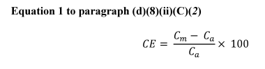
Where:
C m = Average instrument response (ppm).
C a = Certified cylinder gas value (ppm).
(3) You must use a calibration gas or multiple gases that includes the compounds that are reasonably expected to be present in the flare gas stream. If multiple calibration gases are necessary to cover all compounds, you must calibrate the instrument on all of the gases. You may only use the compounds used to calibrate the mass spectrometer in the calculation of the vent gas NHV.
(4) In lieu of the calibration gas described in paragraph (d)(8)(ii)(C)(3) of this section, you may use a surrogate calibration gas consisting of hydrogen and C1 through C5 normal hydrocarbons. All of the calibration gases may be combined in one cylinder. If multiple calibration gases are necessary to cover all compounds, you must calibrate the instrument on all of the gases. For unknown gas components that have similar analytical mass fragments to calibration compounds, you may report the unknowns as an increase in the overlapped calibration gas compound. For unknown compounds that produce mass fragments that do not overlap calibration compounds, you may use the response factor for the nearest molecular weight hydrocarbon in the calibration mix to quantify the unknown component. You may use the response factor for n-pentane to quantify any unknown components detected with a higher molecular weight than n-pentane.
(5) You must perform an initial calibration to identify mass fragment overlap and response factors for the target compounds.
(6) To determine the NHV of the vent gas, determine the product of the volume fraction of the individual component in the vent gas and the net heating value of that individual component. Sum the products for all components in the vent gas to determine the NHV for the vent gas. For the net heating value of each individual component, use the net heating value at 25 °C and 1 atmosphere.
(D) A grab sampling system capable of collecting an evacuated canister sample for subsequent compositional analysis at least once every eight hours. Subsequent compositional analysis of the samples must be performed according to ASTM D1945–14 (R2019) (incorporated by reference, see §60.17). To determine the NHV of the vent gas, determine the product of the volume fraction of the individual component in the vent gas and the net heating value of that individual component. Sum the products for all components in the vent gas to determine the NHV for the vent gas. For the net heating value of each individual component, use the net heating value at 25 °C and 1 atmosphere.
(iii) For an unassisted or pressure-assisted flare or enclosed combustion device, if you demonstrate according to the methods described in paragraphs (d)(8)(iii)(A) through (F) of this section that the NHV of the inlet gas to the enclosed combustion device or flare consistently exceeds the applicable operating limit specified in §60.5415c(e)(1)(vii)(B) or (C)(1), continuous monitoring of the NHV is not required, but you must conduct the ongoing sampling in paragraph (d)(8)(iii)(G) of this section. For flares and enclosed combustion devices that use only perimeter assist air and do not use steam assist or premix assist air, if you demonstrate according to the methods described in paragraphs (d)(8)(iii)(A) through (F) of this section that the NHV of the inlet gas to the enclosed combustion device or flare consistently exceeds 300 Btu/scf, continuous monitoring of the NHV is not required, but you must conduct the ongoing sampling in paragraph (d)(8)(iii)(G) of this section. For an unassisted or pressure-assisted flare or enclosed combustion device, in lieu of conducting the demonstration outlined in paragraphs (d)(8)(iii)(A) through (D) of this section, you may conduct the demonstration outlined in paragraph (d)(8)(iii)(H) of this section, but you must still comply with paragraphs (d)(8)(iii)(E) through (G) of this section.
(A) Continuously monitor or collect a sample of the inlet gas to the enclosed combustion device or flare twice daily to determine the average NHV of the gas stream for 14 consecutive operating days. If you do not continuously monitor the NHV, the minimum time of collection for each individual sample be at least one hour. Consecutive samples must be separated by at least 6 hours. If inlet gas flow is intermittent such that there are not at least 28 samples over the 14 operating day period, you must continue to collect samples of the inlet gas beyond the 14 operating day period until you collect a minimum of 28 samples.
(B) If you collect samples twice per day, count the number of samples where the NHV value is less than 1.2 times the applicable operating limit specified in §60.5415c(e)(1)(vii)(B) or (C)(1), or paragraph (d)(8)(iii) of this section (i.e., values that are less than 240, 360, or 960 Btu/scf, as applicable) during the sample collection period in paragraph (d)(8)(iii)(A) of this section.
(C) If you continuously sample the inlet stream for 14 days, count the number of hourly average NHV values that are less than the applicable operating limit specified in §60.5415c(e)(1)(vii)(B) or (C)(1), or paragraph (d)(8)(iii) of this section (i.e., values that are less than 200, 300, or 800 Btu/scf, as applicable), during the sample collection period in paragraph (d)(8)(iii)(A) of this section.
(D) If there are no samples counted under paragraph (d)(8)(iii)(B) of this section or there are no hourly values counted under paragraph (d)(8)(iii)(C) of this section, the gas stream is considered to consistently exceed the applicable NHV operating limit and on-going continuous monitoring is not required.
(E) If process operations are revised that could impact the NHV of the gas sent to the enclosed combustion device or flare, such as the removal or addition of process equipment, and at any time the Administrator requires, re-evaluation of the gas stream must be performed according to paragraphs (d)(8)(iii)(A) through (D) of this section to ensure the gas stream still consistently exceeds the applicable operating limit specified in §60.5415c(e)(1)(vii)(B) or (1">(C)(1), or paragraph (d)(8)(iii) of this section.
(F) When collecting samples under paragraph (d)(8)(iii)(A) of this section, the owner or operator must account for any sources of inert gases that can be sent to the enclosed combustion device or flare (e.g., streams from compressors in acid gas service, streams from enhanced oil recovery facilities). The report in §60.5420c(b)(10)(v)(I) and the records of the demonstration in §60.5420c(c)(10)(vi) must note whether the enclosed combustion device or flare has the potential to receive inert gases, and if so, whether the sampling included periods where the highest percentage of inert gases were sent to the enclosed combustion device or flare. If the introduction of inerts is intermittent and does not occur during the initial demonstration, the introduction of inerts will be considered a revision to process operations that triggers a re-evaluation under paragraph (d)(8)(iii)(E) of this section. If conditions at the site did not allow sampling during periods where the introduction of inert gases was at the highest percentage possible, increasing the percentage of inerts will be considered a revision to process operations that triggers a re-evaluation under paragraph (d)(8)(iii)(E) of this section.
(G) You must collect three samples of the inlet gas to the enclosed combustion device or flare at least once every 5 years. The minimum time of collection for each individual sample must be at least one hour. The samples must be taken during the period with the lowest expected NHV (i.e., the period with the highest percentage of inerts). The first set of periodic samples must be taken, or continuous monitoring commenced, no later than 60 calendar months following the last sample taken under paragraph (d)(8)(iii)(A) of this section. Subsequent periodic samples must be taken, or continuous monitoring commenced, no later than 60 calendar months following the previous sample. If any sample has an NHV value less than 1.2 times the applicable operating limit specified in §60.5415c(e)(1)(vii)(B) or (1">(C)(1), or paragraph (d)(8)(iii) of this section (i.e., values that are less than 240, 360, or 960 Btu/scf, as applicable), you must conduct the monitoring required by paragraph (d)(8)(ii) of this section.
(H) You may request an alternative test method under §60.5412c(d) to demonstrate that the flare or enclosed combustion device reduces methane and VOC in the gases vented to the device by 95.0 percent by weight or greater. You must use an alternative test method that demonstrates compliance with the combustion efficiency limit; you may not use an alternative test method that demonstrates compliance with NHV cz and NHV dil in lieu of measuring combustion efficiency directly. You must measure data values at the frequency specified in the alternative test method and conduct the quality assurance and quality control requirements outlined in the alternative test method at the frequency outlined in the alternative test method. You must monitor the combustion efficiency of the flare continuously for 14 days. If there are no values of the combustion efficiency measured by the alternative test method that are less than 95.0 percent, the gas stream is considered to consistently exceed the applicable NHV operating limit, and you are not required to continuously monitor the NHV of the inlet gas to the flare or enclosed combustion device.
(iv) Except as noted in paragraphs (d)(8)(iv)(A) through (E) of this section, a continuous parameter monitoring system for measuring the flow of gas to the enclosed combustion device or flare. You may use direct flow meters or other parameter monitoring systems combined with engineering calculations, such as inlet line pressure, line size, and burner nozzle dimensions, to satisfy this requirement. The monitoring instrument must have an accuracy of ±10 percent or better at the maximum expected flow rate.
(A) Pressure-assisted flares and pressure-assisted enclosed combustion devices are not required to have a continuous parameter monitoring system for measuring the inlet flow of gas to the device if you install, calibrate, maintain, and operate a backpressure regulator valve calibrated to open at the minimum pressure set point corresponding to the minimum inlet gas flow rate. The set point must be consistent with manufacturer specifications for minimum flow or pressure and must be supported by an engineering evaluation. At least annually, you must confirm that the backpressure regulator valve set point is correct and consistent with the engineering evaluation and manufacturer specifications and that the valve fully closes when not in the open position.
(B) Unassisted flares are not required to have a continuous parameter monitoring system for measuring the inlet flow of gas to the device if you meet the conditions in paragraphs (d)(8)(iv)(B)(1) and (2) of this section.
(1) You must demonstrate, based on the maximum potential pressure of units manifolded to the flare and applicable engineering calculations for the manifolded closed vent system, that the maximum flow rate to the flare cannot cause the flare tip velocity to exceed 18.3 meter/second (60 feet/second). If there are changes to the process or control device that can be reasonably expected to impact the maximum flow rate to the flare, you must conduct a new demonstration to determine whether the maximum flow rate to the flare is less than 18.3 meter/second (60 feet/second).
(2) You must install, calibrate, maintain, and operate a backpressure regulator valve calibrated to open at the minimum pressure set point corresponding to the minimum inlet gas flow rate. The set point must be consistent with manufacturer specifications for minimum flow or pressure and must be supported by an engineering evaluation. At least annually, you must confirm that the backpressure regulator valve set point is correct and consistent with the engineering evaluation and manufacturer specifications and that the valve fully closes when not in the open position.
(C) Unassisted enclosed combustion devices are not required to have a continuous parameter monitoring system for measuring the inlet flow of gas to the device if you meet the conditions in paragraphs (d)(8)(iv)(C)(1) and (2) of this section.
(1) You must demonstrate, based on the maximum potential pressure of units manifolded to the enclosed combustion device and applicable engineering calculations for the manifolded closed vent system, that the maximum flow rate to the enclosed combustion device cannot cause the maximum inlet flow rate established in accordance with paragraph (f)(1) of this section to be exceeded. If there are changes to the process or control device that can be reasonably expected to impact the maximum flow rate to the enclosed combustion device, you must conduct a new demonstration to determine whether the maximum flow rate to the enclosed combustor is less than the maximum inlet flow rate established in accordance with paragraph (f)(1) of this section.
(2) You must install, calibrate, maintain, and operate a backpressure regulator valve calibrated to open at the minimum pressure set point corresponding to the minimum inlet gas flow rate. The set point must be consistent with manufacturer specifications for minimum flow or pressure and must be supported by an engineering evaluation. At least annually, you must confirm that the backpressure regulator valve set point is correct and consistent with the engineering evaluation and manufacturer specifications and that the valve fully closes when not in the open position.
(D) Air-assisted flares or enclosed combustion devices that use only perimeter assist air and have no assist steam or premix assist air are not required to have a continuous parameter monitoring system for measuring the inlet flow of gas to the device or the flow of assist air if you meet the conditions in paragraphs (d)(8)(iv)(D)(1) and (2) of this section. For these flares and enclosed combustion devices, NHV cz is assumed to be equal to the vent gas NHV.
(1) You must install, calibrate, maintain, and operate a backpressure regulator valve calibrated to open at the minimum pressure set point corresponding to the minimum inlet gas flow rate. The set point must be consistent with manufacturer specifications for minimum flow or pressure and must be supported by an engineering evaluation. At least annually, you must confirm that the backpressure regulator valve set point is correct and consistent with the engineering evaluation and manufacturer specifications and that the valve fully closes when not in the open position.
(2) You must demonstrate, based on the maximum flow rate of perimeter assist air to the enclosed combustion device or flare and applicable engineering calculations, that the NHV dil can never be less than the minimum required NHV dil. The demonstration must clearly document why the maximum flow rate of perimeter assist air will never exceed the rate used in the demonstration. You must use the minimum flow rate of vent gas allowed by your backpressure regulator valve and the minimum expected value of the NHV of the inlet gas to the enclosed combustion device or flare based on previous sampling results or process knowledge of the streams sent to the enclosed combustion device or flare in your demonstration. You must update this demonstration if there are changes to the backpressure regulator valve, the backpressure regulator valve set point, or the maximum flow rate of perimeter assist air. You must also update this demonstration if any sampling results of the NHV of the inlet gas to the enclosed combustion device or flare under paragraphs (d)(8)(ii) or (iii) of this section are lower than the NHV vent gas value used in your demonstration.
(E) Air-assisted flares or enclosed combustion devices that use only premix assist air and have no assist steam or perimeter assist air are not required to have a continuous parameter monitoring system for measuring the inlet flow of gas to the device or the flow of assist air if you meet the conditions in paragraphs (d)(8)(iv)(E)(1) and (2) of this section.
(1) You must install, calibrate, maintain, and operate a backpressure regulator valve calibrated to open at the minimum pressure set point corresponding to the minimum inlet gas flow rate. The set point must be consistent with manufacturer specifications for minimum flow or pressure and must be supported by an engineering evaluation. At least annually, you must confirm that the backpressure regulator valve set point is correct and consistent with the engineering evaluation and manufacturer specifications and that the valve fully closes when not in the open position.
(2) You must demonstrate, based on the maximum flow rate of premix assist air to the enclosed combustion device or flare and applicable engineering calculations, that the NHV cz will never be less than the minimum required NHV cz. The demonstration must clearly document why the maximum flow rate of premix assist air will never exceed the rate used in the demonstration. You must use the minimum flow rate of vent gas allowed by your backpressure regulator valve in and the minimum expected value of the NHV of the inlet gas to the enclosed combustion device or flare based on previous sampling results or process knowledge of the streams sent to the enclosed combustion device or flare in your demonstration. You must update this demonstration if there are changes to the backpressure regulator valve, the backpressure regulator valve set point, or the maximum flow rate of premix assist air. You must also update this demonstration if any sampling results of the NHV of the inlet gas to the enclosed combustion device or flare under paragraphs (d)(8)(ii) or (iii) of this section are lower than the NHV vent gas value used in your demonstration.
(v) Conduct inspections monthly and at other times as requested by the Administrator to monitor for visible emissions from the combustion device using section 11 of Method 22 of appendix A to this part or conduct visible emissions monitoring according to paragraph (h) of this section. The observation period shall be 15 minutes or once the amount of time visible emissions is present has exceeded 1 minute. Devices must be operated with no visible emissions, except for periods not to exceed a total of 1 minute during any 15-minute period.
(vi) If you use a flare or enclosed combustion device that is air-assisted or steam-assisted, you must also meet the following requirements.
(A) Except as allowed by paragraph (d)(8)(iv)(E) of this section, you must monitor and calculate NHV cz as specified in §63.670(m) of this chapter. Additionally, for flares and enclosed combustion devices that use only perimeter assist air and do not use steam assist or premix assist air, the NHV cz is equal to the vent gas NHV. When NHV cz is equal to the vent gas NHV, you are not required to continuously monitor NHV cz if you meet the requirements in paragraph (d)(8)(iii) of this section.
(B) Except as allowed by paragraph (d)(8)(iv)(D) of this section, for each flare using perimeter assist air, you must also monitor and calculate NHV dil as specified in §63.670(n) of this chapter. If the only assist air provided to the flare or enclosed combustion control device is perimeter assist air intentionally entrained in lower and/or upper steam at the flare tip and the effective diameter is 9 inches or greater, you are only required to comply with the NHV cz limit specified in paragraph (f)(8)(vi)(A) of this section.
(C) Except as allowed by paragraph (d)(8)(iv) of this section, you must monitor the flare vent gas and assist gas as specified in §63.670(i) of this chapter.
(D) You must determine the flare vent gas net heating value as specified in §63.670(l) of this chapter using one of the methods specified in paragraph (d)(8)(ii) of this section. Where the phrase “petroleum refinery” is used, for purposes of this subpart, it will refer to flares controlling an affected facility under this subpart. If you are not required to continuously monitor the NHV of the inlet gas because you have demonstrated that it consistently exceeds the applicable operating limit as provided in paragraph (d)(8)(iii) of this section, you must use the lowest net heating value measured in the sampling program in paragraph (d)(8)(iii) of this section for the calculations performed in paragraphs (d)(8)(vi)(A) and (B) of this section. You must update this value if a subsequent sampling result of the NHV of the inlet gas to the enclosed combustion device or flare under paragraph (d)(8)(iii) of this section is lower than the NHV vent gas value used in your calculations.
(e) Calculate the value of the applicable monitored parameter in accordance with paragraphs (e)(1) through (5) of this section.
(1) You must calculate the daily average value for condenser outlet temperature for each operating day, using the data recorded by the monitoring system. If the emissions unit operation is continuous, the operating day is a 24-hour period. If the emissions unit operation is not continuous, the operating day is the total number of hours of control device operation per 24-hour period. Valid data points must be available for 75 percent of the operating hours in an operating day to compute the daily average.
(2) You must use the 5-minute readings from the heat sensing devices to assess the presence of a pilot or combustion flame.
(3) You must use the regeneration cycle time (i.e., duration of the carbon bed steaming cycle) for each regenerative-type carbon adsorption system to calculate the average parameter to compare with the maximum steam mass flow or volumetric flow during each carbon bed regeneration cycle and the maximum carbon bed temperature during the steaming cycle. The carbon bed temperature after the regeneration cycle should not be averaged; you must use the carbon bed temperature measured within 15 minutes of completing the cooling cycle to compare with the minimum carbon bed temperature after the regeneration cycle.
(4) You must use 15-minute blocks to calculate NHV cz and NHV dil .
(5) For all operating parameters others than those described in paragraphs (e)(1) through (4) of this section, you must calculate the 3-hour rolling average of each monitored parameter. For each operating hour, calculate the hourly value of the operating parameter from your continuous monitoring system. Average the three most recent hours of data to determine the 3-hour average. Determine the 3-hour rolling average by recalculating the 3-hour average each hour.
(f) For each operating parameter monitor installed in accordance with the requirements of paragraph (d) of this section, you must comply with paragraph (f)(1) of this section for all control devices. When condensers are installed, you must also comply with paragraph (f)(2) of this section.
(1) You must establish a minimum operating parameter value or a maximum operating parameter value, as appropriate for the control device, to define the conditions at which the control device must be operated to continuously achieve the applicable performance requirements of §60.5412c(a)(1) or (2). You must establish each minimum or maximum operating parameter value as specified in paragraphs (f)(1)(i) through (iv) of this section.
(i) If you conduct performance tests in accordance with the requirements of §60.5413c(b) to demonstrate that the control device achieves the applicable performance requirements specified in §60.5412c(a)(1) or (2), then you must establish the minimum operating parameter value or the maximum operating parameter value based on values measured during the performance test and supplemented, as necessary, by a condenser or carbon adsorption system design analysis or control device manufacturer recommendations or a combination of both. If you operate an enclosed combustion device, you must establish the maximum inlet flow rate based on values measured during the performance test and you may establish the minimum inlet flow rate based on control device manufacturer recommendations.
(ii) If you use a condenser or carbon adsorption system design analysis in accordance with the requirements of §60.5413c(c) to demonstrate that the control device achieves the applicable performance requirements specified in §60.5412c(a)(2), then you must establish the minimum operating parameter value or the maximum operating parameter value based on the design analysis and supplemented, as necessary, by the manufacturer's recommendations.
(iii) If you operate a control device where the performance test requirement was met under §60.5413c(d) to demonstrate that the control device achieves the applicable performance requirements specified in §60.5412c(a)(1), then your control device inlet gas flow rate must be equal to or greater than the minimum inlet gas flow rate and equal to or less than the maximum inlet gas flow rate determined by the manufacturer.
(iv) If you operate an enclosed combustion device where the combustion zone temperature is not an indicator of destruction efficiency or a control device where the performance test requirement was met under §60.5413c(d), you must maintain the NHV of the gas sent to the enclosed combustion device, the NHV cz , and the NHV dil above the applicable limits specified in §60.5412c(a)(1)(iv)(A) through (D).
(2) If you use a condenser as specified in paragraph (d)(1)(v) of this section, you must establish a condenser performance curve showing the relationship between condenser outlet temperature and condenser control efficiency, according to the requirements of paragraphs (f)(2)(i) and (ii) of this section.
(i) If you conduct a performance test in accordance with the requirements of §60.5413c(b) to demonstrate that the condenser achieves the applicable performance requirements of §60.5412c(a)(2), then the condenser performance curve must be based on values measured during the performance test and supplemented as necessary by control device design analysis, or control device manufacturer's recommendations, or a combination or both.
(ii) If you use a control device design analysis in accordance with the requirements of §60.5413c(c)(1) to demonstrate that the condenser achieves the applicable performance requirements specified in §60.5412c(a)(2), then the condenser performance curve must be based on the condenser design analysis and supplemented, as necessary, by the control device manufacturer's recommendations.
(g) A deviation for a control device is determined to have occurred when the monitoring data or lack of monitoring data result in any one of the criteria specified in paragraphs (g)(1) through (7) of this section being met. If you monitor multiple operating parameters for the same control device during the same operating day and more than one of these operating parameters meets a deviation criterion specified in paragraphs (g)(1) through (7) of this section, then a single excursion is determined to have occurred for the control device for that operating day.
(1) A deviation occurs when the average value of a monitored operating parameter determined in accordance with paragraph (e) of this section is less than the minimum operating parameter limit (and, if applicable, greater than the maximum operating parameter limit) established in paragraph (f)(1) of this section; for flares, when the average value of a monitored operating parameter determined in accordance with paragraph (e) of this section is above the limits specified in §60.5415c(e)(1)(vii)(B); or when the heat sensing device indicates that there is no pilot or combustion flame present for any time period. If you use a backpressure regulator valve to maintain the inlet gas flow to an enclosed combustion device or flare above the minimum value, a deviation occurs if the annual inspection finds that the backpressure regulator valve set point is not set correctly or indicates that the backpressure regulator valve does not fully close when not in the open position.
(2) If you are subject to §60.5412c(a)(2), a deviation occurs when the 365-day average condenser efficiency calculated according to the requirements specified in §60.5415c(e)(1)(ix)(D) is less than 95.0 percent.
(3) If you are subject to §60.5412c(a)(2) and you have less than 365 days of data, a deviation occurs when the average condenser efficiency calculated according to the procedures specified in §60.5415c(e)(1)(ix)(D)(1) or (2) is less than 95.0 percent.
(4) A deviation occurs when the monitoring data are not available for at least 75 percent of the operating hours in a day.
(5) If the closed vent system contains one or more bypass devices that could be used to divert all or a portion of the gases, vapors, or fumes from entering the control device, a deviation occurs when the requirements of paragraph (g)(5)(i) or (ii) of this section are met.
(i) For each bypass line subject to §60.5411c(a)(4)(i)(A), the flow indicator indicates that flow has been detected and that the stream has been diverted away from the control device to the atmosphere.
(ii) For each bypass line subject to §60.5411c(a)(4)(i)(B), if the seal or closure mechanism has been broken, the bypass line valve position has changed, the key for the lock-and-key type lock has been checked out, or the car-seal has broken.
(6) For a combustion control device whose model is tested under §60.5413c(d), a deviation occurs when the conditions of paragraphs (g)(4), (g)(5), or (g)(6)(i) through (vi) of this section are met.
(i) The hourly inlet gas flow rate is less than the minimum inlet gas flow rate or greater than the maximum inlet gas flow rate determined by the manufacturer. If you use a backpressure regulator valve to maintain the inlet gas flow above the minimum value, a deviation occurs if the annual inspection finds that the backpressure regulator valve set point is not set correctly or indicates that the backpressure regulator valve does not fully close when not in the open position.
(ii) Results of the monthly visible emissions test conducted under §60.5413c(e)(3) or monitoring under paragraph (h) of this section indicate visible emissions exceed 1 minute in any 15-minute period.
(iii) There is no indication of the presence of a pilot or combustion flame for any 5-minute time period.
(iv) The control device is not maintained in a leak free condition.
(v) The control device is not operated in accordance with the manufacturer's written operating instructions, procedures and maintenance schedule.
(vi) The NHV of the vent gas, the NHV cz , or the NHV dil is below the applicable limit specified in §60.5412c(a)(1)(iv).
(7) For an enclosed combustion device or flare subject to paragraph (d)(8) of this section, a deviation occurs when any of the conditions described by paragraphs (g)(1), (4), or (5) of this section are met or when the results of the visible emissions monitoring conducted under paragraph (d)(8)(v) or (h) of this section exceed 1 minute in any 15-minute period.
(h) For enclosed combustion devices and flares, in lieu of conducting a visible emissions observation using Method 22 of appendix A–7 to this part, you may use a video surveillance camera to continuously monitor and record the flare flame according to the requirements in paragraphs (h)(1) through (6) of this section.
(1) You must provide real-time high-definition video surveillance camera output (i.e., at least 720p) at a frame rate of at least 15 frames per second to the control room or other continuously manned location where the camera images may be viewed at the same resolution at any time.
(2) You must record at least one frame every 15 seconds with date and time stamp.
(3) The camera must be located at a reasonable distance above the flare flame at an angle suitable for visual emissions observations. The position of the camera should be such that the sun is not in the field of view.
(4) The camera must be located no more than 400 m (0.25 miles) from the emission source.
(5) Operators must look at the video feed at least once daily for an observation period of at least 1 minute to determine if visible emissions are present. If visible emissions are present during a daily observation, the operator must observe the video feed for 15 minutes or until the amount of time visible emissions is present has exceeded 1 minute, whichever time period is less.
(6) Enclosed combustion devices and flares must be operated with no visible emissions, except for periods not to exceed a total of 1 minute during any 15-minute period.
(i) If you use an enclosed combustion device or flare using an alternative test method approved under §60.5412c(d), you must comply with paragraphs (i)(1) through (6) of this section.
(1) You must measure data values at the frequency specified in the alternative test method.
(2) You must prepare a monitoring plan that covers each control device for designated facilities within each company-defined area. The monitoring plan must address the monitoring system design, data collection, and the quality assurance and quality control elements outlined in the alternative test method and in paragraphs (i)(2)(i) through (iii) of this section. You must operate and maintain each monitoring system in accordance with the procedures in your monitoring plan.
(i) The performance criteria and design specifications for the monitoring system equipment.
(ii) Location of monitoring system in relation to the monitored control device.
(iii) Ongoing reporting and recordkeeping procedures.
(3) You must conduct the quality assurance and quality control requirements outlined in the alternative test method at the frequency outlined in the alternative test method.
(4) If required by §60.5412c(d)(4), you must conduct the inspections required by paragraph (d)(8)(v) of this section.
(5) If required by §60.5412c(d)(5), you must install the pilot or combustion flame monitoring system required by paragraph (d)(8)(i) of this section.
(6) A deviation for the control device is determined to have occurred when the monitoring data or lack of monitoring data result in any one of the criteria specified in paragraphs (i)(6)(i) through (v) of this section being met.
(i) A deviation occurs if the combustion efficiency is less than 95.0 percent, the combustion zone NHV is less than 270 Btu/scf, or the NHV dilution parameter is less than 22 Btu/sqft.
(ii) A deviation occurs when the monitoring data are not available for at least 75 percent of the operating hours in a day.
(iii) A deviation occurs when any of the conditions described by paragraph (g)(5) of this section are met.
(iv) If required by paragraph (i)(4) of this section to conduct visible emissions inspections, a deviation occurs when the results of the visible emissions monitoring conducted under paragraph (d)(8)(v) or (h) of this section exceeds 1 minute in any 15-minute period.
(v) If required by paragraph (i)(5) of this section to install a pilot or combustion flame monitoring system, a deviation occurs when there is no indication of the presence of a pilot or combustion flame for any 5-minute period.
(j) You must submit annual reports for control devices as required in §60.5420c(b)(1) and (10). You must maintain records as specified in §60.5420c(c)(10).
[89 FR 17140, Mar. 8, 2024]