['CMV Parts and Maintenance', 'Passenger carriers']
['Passenger vehicles', 'Tires', 'Parts and Accessories - Motor Carrier']
10/30/2024
...
[Editor’s Note: This section is added effective December 30, 2024.][Change Notice]
S1. Scope. This standard establishes performance requirements for bus rollover structural integrity.
S2. Purpose. The purpose of this standard is to reduce death and injuries resulting from the structural collapse of the bus body structure in rollover crashes and from partial and complete ejections through emergency exits opening in such crashes.
S3. Application.
(a) Subject to S3(b), this standard applies to:
(1) Over-the-road buses; and
(2) Buses that are not over-the-road buses, and that have a gross vehicle weight rating (GVWR) greater than 11,793 kilograms (26,000 pounds).
(b) This standard does not apply to:
(1) School buses, school bus derivative buses, transit buses, and prison buses; and
(2) Buses with 7 or fewer designated seating positions rearward of the driver's seating position that are forward-facing or can convert to forward-facing without the use of tools.
S4. Definitions.
Occupant compartment means a space within the vehicle interior intended for driver and passenger use, excluding any space occupied by fixed appliances such as bars, kitchenettes, or toilets.
Over-the-road bus means a bus characterized by an elevated passenger deck located over a baggage compartment.
Prison bus means a bus manufactured for the purpose of transporting persons subject to involuntary restraint or confinement and has design features consistent with that purpose.
School bus is defined in §571.3.
School bus derivative bus means a bus that meets Federal motor vehicle safety standards for school buses regarding emergency exits (§571.217), rollover protection (§571.220), bus body joint strength (§571.221), and fuel system integrity (§571.301).
Stop-request system means a vehicle-integrated system for passenger to use to signal to a vehicle operator that they are requesting a stop.
Survival space means all points within a three-dimensional space in the occupant compartment as defined within the following volume:
(1) The front boundary of the survival space is a transverse vertical plane forward of the most forward seat (whether passenger, or driver seat) when the seat back is in the manufacturer's nominal design riding position. This transverse vertical plane is:
(i) For a forward-facing seat, 600 millimeters (mm) in front of the forward most point on the longitudinal centerline of the front surface of the seat back when the seat is in its forward most position;
(ii) For a rearward-facing seat, through the most forward point (relative to the vehicle) on the longitudinal centerline of the seat back when the seat is in its forward most position with respect to the vehicle;
(iii) For a side-facing seat, through the most forward point (relative to the vehicle) on the seat, including the seat back, seat arm rest, and seat cushion.
(2) The rear boundary of the survival space is the inside surface of the rear wall of the occupant compartment of the vehicle.
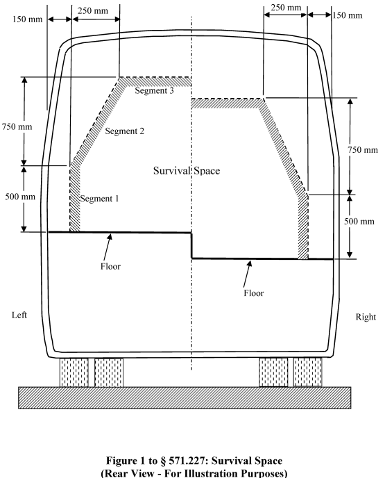
(3) The outer boundary of the survival space at any transverse cross section between, or at the front and rear boundaries, is defined on each side of the vehicle by the occupant compartment floor and the following three line segments (see Figure 1 of this section, provided for illustration purposes only):
(i) Segment 1 extends vertically from the floor to an end point that is 500 mm above the floor and 150 mm inboard of the side wall.
(ii) Segment 2 starts at the end point of Segment 1. The end point of Segment 2 is 750 mm vertically above and 250 mm horizontally inboard of the end point of Segment 1.
(iii) Segment 3 is a horizontal line that starts at the end point of Segment 2 and ends at the vertical longitudinal center plane of the vehicle.
Transit bus means a bus that is equipped with a stop-request system sold for public transportation provided by, or on behalf of, a State or local government and that is not an over-the-road bus. [Change Notice] [New Text]
S5. Requirements. When tested under the conditions in S6 and the test procedures specified in S7, each bus shall meet the requirements in S5.1 and S5.2.
S5.1 Survival space intrusion. No part of the vehicle that is outside the survival space shall intrude into the survival space during the movement of the tilting platform or resulting from impact of the vehicle on the impact surface, except as provided below in this paragraph.
(a) Items separated from the vehicle and with a mass less than 15.0 grams that enter the survival space will not be considered for this evaluation of survival space intrusion. [Change Notice] [New Text]
(b) Portions of a bus over which there is not a permanent roof, such as the upper level of an open-top double-decker bus, will not be considered for this evaluation.
S5.2 Opening of Emergency exits. Emergency exits shall not open during the movement of the tilting platform or resulting from impact of the vehicle on the impact surface.
S6. Test conditions.
S6.1 Tilting platform.
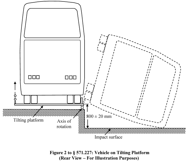
S6.1.1 The tilting platform has a top surface that rests horizontally at its initial position and is of sufficient size to fully contact the bottom of the vehicle's tires, as shown in Figure 2 of this section (figure provided for illustration purposes only).
S6.1.2 The top surface of the tilting platform, at its initial position, is 800 ± 20 millimeters (mm) above the impact surface specified in S6.1.6, as shown in Figures 1 and 2 of this section (figures provided for illustration purposes only).
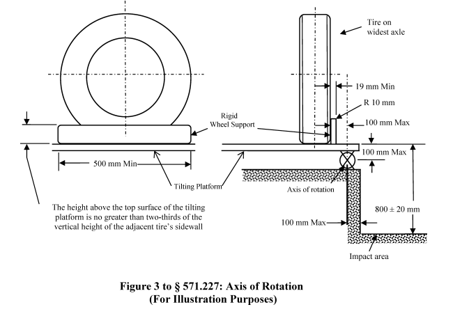
S6.1.3 The axis of rotation of the tilting platform is a maximum of a 100 mm horizontal distance from the edge of the impact surface closest to the platform and a maximum of 100 mm below the horizontal plane at the top surface of the tilting platform as shown in Figure 3 of this section (figure provided for illustration purposes only).
S6.1.4 The tilting platform is equipped with rigid wheel supports on the top surface as illustrated in Figure 3 of this section (figure provided for illustration purposes only). At each vehicle axle, the wheel closest to the platform's axis of rotation is supported. The rigid wheel supports are positioned to make contact with the outboard tire sidewall of the supported wheels with the vehicle positioned as specified in S6.3.1 to prevent sliding of the vehicle during the test. Each rigid wheel support has the following dimensions: [Change Notice] [New Text]
(a) The height above the top surface of the tilting platform is no greater than two-thirds of the vertical height of the adjacent tire's sidewall.
(b) The width is a minimum of 19 mm.
(c) The length is a minimum of 500 mm.
(d) The top inboard edge has a radius of 10 mm.
S6.1.5 While raising the platform, the tilting platform roll angle, measured at the outside of each wheel farthest from the pivot point, does not differ by more than one degree.
S6.1.6 The impact surface is horizontal, uniform, dry, and smooth concrete. The impact surface covers an area that is large enough to ensure that the vehicle does not strike beyond the impact surface edges.
S6.2 Vehicle preparation.
S6.2.1 The vehicle's tires are inflated to the manufacturer's recommended tire pressure.
S6.2.2 Test equipment may be attached securely to the bus structure such that the equipment does not break away from the bus structure from the time the tilting platform begins movement to after the vehicle comes to rest on the impact surface.
S6.2.3 Fixed seats may be removed or adjustable seats repositioned for the installation of test equipment in the survival space. Ballast of any weight up to the weight of the removed seat and 68 kg per designated seating position may be secured to the bus floor. The ballasts are not placed farther forward than the forward most point of the vehicle seat immediately in front of the removed seat, and the ballasts are not placed farther rearward than the rear most point of the vehicle seat immediately behind the removed seat.
S6.2.4 The fuel tank is filled to any level from 90 to 95 percent of capacity. All other vehicle fluids are filled to any level from 90 to 95 percent of capacity. Fluids may be substituted if the weight of the original fluid is maintained.
S6.2.5 Ballasting. The vehicle is loaded to any weight up to and including the GVWR. Up to 68 kilograms (150 pounds) of ballast is installed at all designated seating positions that are equipped with occupant restraints. The ballast is placed on the top of each seat cushion and attached securely to the seat frame such that it does not break away from the seat from the time the tilting platform begins movement to after the vehicle comes to rest on the impact surface.
S7 Rollover structural integrity test procedure. Each vehicle shall meet the requirements of S5 when prepared as specified in S6.2 and tested in accordance with the procedures set forth in paragraphs (a) through (f) of this S7.
(a) Position the vehicle on the tilting platform as illustrated in the examples of Figures 2 and 3 of this section with its longitudinal centerline parallel to the tilt platform's axis of rotation, the right or left side facing the impact surface at NHTSA's option, and with the outboard tire sidewall at the widest axle within 100 mm of the axis of rotation. (Figures provided for illustration purposes only.)
(b) Apply the vehicle parking brakes.
(c) Attach a rigid wheel support to the tilting platform at each axle of the vehicle so that it contacts the outboard tire sidewall of the wheel closest to the impact surface.
(d) Block the suspension system of the vehicle to be within ±25 mm of the normal riding attitude as loaded in S6.2.5.
(e) Vehicle windows, doors, and emergency exits are fully closed and latched but not locked.
(f) Tilt the vehicle at a rate not to exceed 5 degrees/second until it starts to rollover on its own.


[86 FR 74303 Dec. 29, 2021; 88 FR 77523, Nov. 13, 2023]
READ MORESHOW LESS
['CMV Parts and Maintenance', 'Passenger carriers']
['Passenger vehicles', 'Tires', 'Parts and Accessories - Motor Carrier']
Load More
J. J. Keller is the trusted source for DOT / Transportation, OSHA / Workplace Safety, Human Resources, Construction Safety and Hazmat / Hazardous Materials regulation compliance products and services. J. J. Keller helps you increase safety awareness, reduce risk, follow best practices, improve safety training, and stay current with changing regulations.
Copyright 2024 J. J. Keller & Associate, Inc. For re-use options please contact copyright@jjkeller.com or call 800-558-5011.
