...
(a) The procedures for determining compliance with §61.302(b) for all control devices other than flares is as follows:
(1) All testing equipment shall be prepared and installed as specified in the appropriate test methods.
(2) The time period for a performance test shall be not less than 6 hours, during which at least 300,000 liters of benzene are loaded. If the throughput criterion is not met during the initial 6 hours, the test may be either continued until the throughput criterion is met, or resumed the next day with at least another 6 complete hours of testing.
(3) For intermittent control devices:
(i) The vapor holder level of the intermittent control device shall be recorded at the start of the performance test. The end of the performance test shall coincide with the time when the vapor holder is at its original level.
(ii) At least two startups and shutdowns of the control device shall occur during the performance test. If this does not occur under an automatically controlled operation, the system shall be manually controlled.
(4) An emission testing interval shall consist of each 5-minute period during the performance test. For each interval:
(i) The reading from each measurement instrument shall be recorded.
(ii) Method 1 or 1A of part 60, appendix A, as appropriate, shall be used for selection of the sampling site,
(iii) The volume exhausted shall be determined using Method 2, 2A, 2C, or 2D of part 60, appendix A, as appropriate.
(iv) The average benzene concentration upstream and downstream of the control device in the vent shall be determined using Method 25A or Method 25B of appendix A of this part, using benzene as the calibration gas. The average benzene concentration shall correspond to the volume measurement by taking into account the sampling system response time.
(5) The mass emitted during each testing interval shall be calculated as follows:
Mi = FKVS C
where:
Mi = Mass of benzene emitted during testing interval i, kg.
Vs = Volume of air-vapor mixture exhausted, m 3 at standard conditions.
C = Benzene concentration (as measured) at the exhaust vent, ppmv.
K = Density, (kg/m 3 benzene), standard conditions.
K = 3.25 for benzene.
F = Conversion factor, (m 3 benzene/m 3 air)(1/ppmv).
F = 10/?6/.
s = Standard conditions, 20°C and 760 mm Hg.
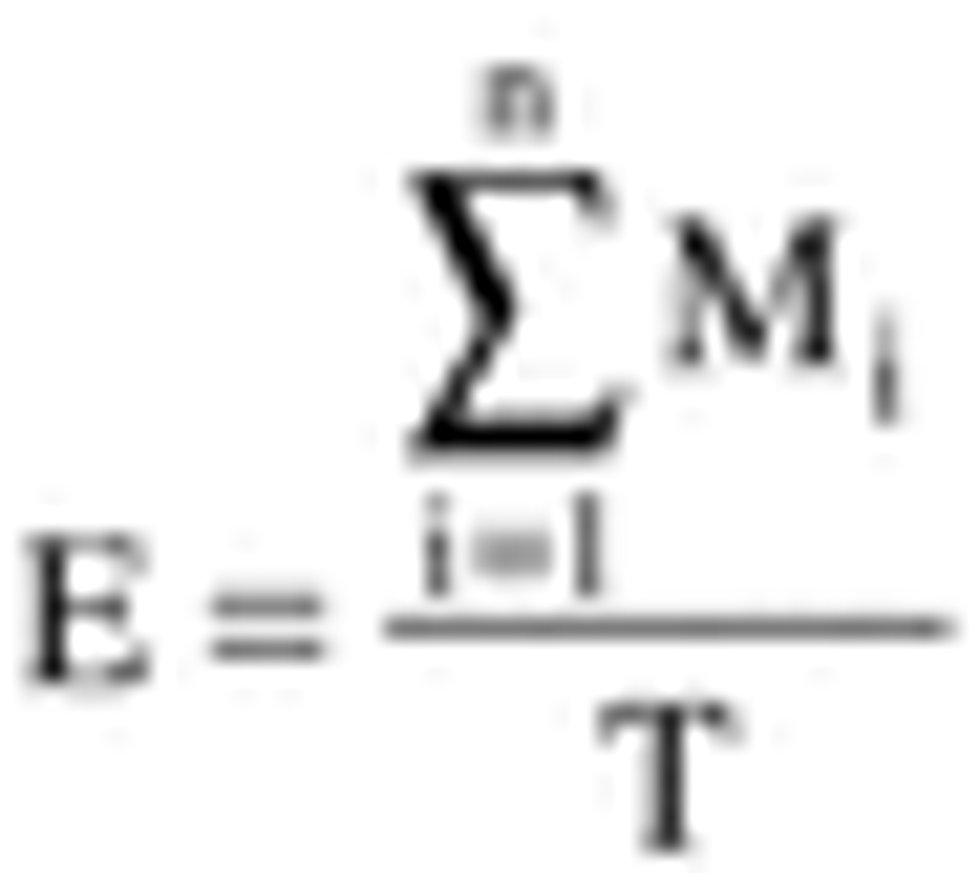
(6) The benzene mass emission rates before and after the control device shall be calculated as follows:

where:
E = Mass flow rate of benzene emitted, kg/hr.
Mi = Mass of benzene emitted during testing interval i, kg.
T = Total time of all testing intervals, hr.
n = Number of testing intervals.
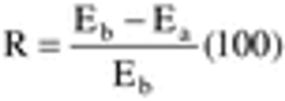
(7) The percent reduction across the control device shall be calculated as follows:

where:
R = Control efficiency of control device, %.
Eb = Mass flow rate of benzene prior to control device, kg/hr.
Ea = Mass flow rate of benzene after control device, kg/hr.
(b) When a flare is used to comply with §61.302(b), a performance test according to Method 22 of appendix A of 40 CFR part 60 shall be performed to determine visible emissions. The observation period shall be at least 2 hours. Performance testing shall be conducted during at least three complete loading cycles with a separate test run for each loading cycle. The observation period for detecting visible emissions shall encompass each loading cycle. Integrated sampling to measure process vent stream flow rate shall be performed continuously during each loading cycle.
(c) For the purpose of determining compliance with §61.302(h), the following procedures shall be used:
(1) Calibrate and install a pressure measurement device (liquid manometer, magnehelic gauge, or equivalent instrument), which has a precision of ±2.5 mm H20 in the range that the tank truck or railcar was initially pressured to during the most recent vapor-tightness test.
(2) Connect the pressure measurement device to a pressure tap in the affected facility's vapor collection system, located as close as possible to the connection with the tank truck or railcar.
(3) During the performance test, record the pressure every 5 minutes while a tank truck or railcar is being loaded, and record the highest instantaneous pressure that occurs during each loading cycle. Every loading rack shall be tested at least once during the performance test.
(4) If more than one loading rack is used simultaneously, then the performance test shall be conducted simultaneously to represent the maximum capacity.
(d) For the purpose of determining compliance with §61.302(j), the following procedures shall be used:
(1) Calibrate and install a pressure measurement device (liquid manometer, magnehelic gauge, or equivalent instrument), capable of measuring up to the relief set pressure of the pressure-vacuum vents.
(2) Connect the pressure measurement device to a pressure tap in the affected facility's vapor collection system, located as close as possible to the connection with the marine vessel.
(3) During the performance test, record the pressure every 5 minutes while a marine vessel is being loaded, and record the highest instantaneous pressure that occurs during each loading cycle.
(e) Immediately prior to a performance test required for determination of compliance with §61.302(b), all potential sources of vapor leakage in the affected facility's vapor collection system equipment shall be inspected for detectable emissions as required in §61.302(k). The monitoring shall be conducted only while a vapor-tight tank truck, railcar, or marine vessel is being loaded. All identified leaks in the terminal's vapor collection system shall be repaired prior to conducting the performance test.
(f) The following test method shall be used to comply with the marine vessel vapor-tightness requirements of §61.302(e)(3):
(1) Each benzene product tank shall be pressurized with dry air or inert gas to not less than 1.0 psig and not more than the pressure of the lowest relief valve setting.
(2) Once the pressure is obtained, the dry air or inert gas source shall be shut off.
(3) At the end of one-half hour, the pressure in the benzene product tank and piping shall be measured. The change in pressure shall be calculated using the following formula:
? P = Pi - Pf
where:
? P = Change in pressure, inches of water.
Pi = Pressure in tank when air/gas source is shut off, inches of water.
Pf = Pressure in tank at the end of one-half hour after air/gas source is shut off, inches of water.
(4) The change in pressure, ? P, shall be compared to the pressure drop calculated using the following formula:
? PM = 0.861 Pia L/V
where:
? PM = Maximum allowable pressure change, inches of water.
Pia = Pressure in tank when air/gas source is shut off, pounds per square inch, absolute (psia).
L = Maximum permitted loading rate of vessel, barrels per hour.
V = Total volume of product tank, barrels.
(5) If ?P??PM, the vessel is vapor tight.
(6) If ?P>?PM, the vessel is not vapor tight and the source of the leak must be identified and repaired prior to retesting.
[55 FR 8341, Mar. 7, 1990; 55 FR 12444, Apr. 3, 1990, as amended at 65 FR 62159, Oct. 17, 2000]
