['General Packaging Requirements - Hazmat']
['Hazmat Package Testing']
06/23/2022
...
(a) Criteria for Acceptance. (1) At least three specimens of the outer packaging materials must be tested;
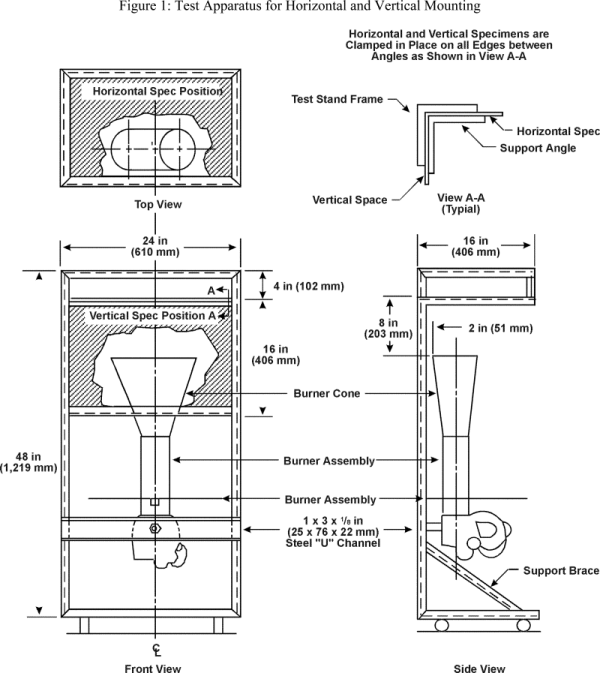
(2) Each test must be conducted on a flat 16 inch x 24 inch test specimen mounted in the horizontal ceiling position of the test apparatus to represent the outer packaging design;
(3) Testing must be conducted on all design features (latches, seams, hinges, etc.) affecting the ability of the outer packaging to safely prevent the passage of fire in the horizontal ceiling position; and
(4) There must be no flame penetration of any specimen within 5 minutes after application of the flame source and the maximum allowable temperature at a point 4 inches above the test specimen, centered over the burner cone, must not exceed 205°C (400°F).
(b) Summary of Method. This method provides a laboratory test procedure for measuring the capability of cargo compartment lining materials to resist flame penetration with a 2 gallon per hour (GPH) #2 Grade kerosene or equivalent burner fire source. Ceiling and sidewall liner panels may be tested individually provided a baffle is used to simulate the missing panel. Any specimen that passes the test as a ceiling liner panel may be used as a sidewall liner panel.
(c) Test Specimens. (1) The specimen to be tested must measure 16 ±1/8 inches (406 ±3 mm) by 24 1/8 inches (610 ±3 mm).
(2) The specimens must be conditioned at 70°F. ±5°F. (21°C. ±2°C.) and 55% ±5% humidity for at least 24 hours before testing.
(d) Test Apparatus. The arrangement of the test apparatus must include the components described in this section. Minor details of the apparatus may vary, depending on the model of the burner used.
(1) Specimen Mounting Stand. The mounting stand for the test specimens consists of steel angles.
(2) Test Burner. The burner to be used in tesing must—
(i) Be a modified gun type.
(ii) Use a suitable nozzle and maintain fuel pressure to yield a 2 GPH fuel flow. For example: An 80 degree nozzle nominally rated at 2.25 GPH and operated at 85 pounds per square inch (PSI) gauge to deliver 2.03 GPH.
(iii) Have a 12 inch (305 mm) burner extension installed at the end of the draft tube with an opening 6 inches (152 mm) high and 11 inches (280 mm) wide.
(iv) Have a burner fuel pressure regulator that is adjusted to deliver a nominal 2.0 GPH of #2 Grade kerosene or equivalent.
Burner models which have been used successfully in testing are the Lenox Model OB–32, Carlin Model 200 CRD and Park Model DPL.
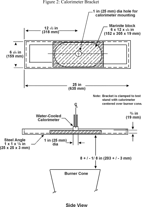
(3) Calorimeter. (i) The calorimeter to be used in testing must be a total heat flux Foil Type Gardon Gage of an appropriate range (approximately 0 to 15.0 British thermal unit (BTU) per ft.2 sec., 0–17.0 watts/cm2). The calorimeter must be mounted in a 6 inch by 12 inch (152 by 305 mm) by ¾ inch (19 mm) thick insulating block which is attached to a steel angle bracket for placement in the test stand during burner calibration as shown in Figure 2 of this part of this appendix.
(ii) The insulating block must be monitored for deterioration and the mounting shimmed as necessary to ensure that the calorimeter face is parallel to the exit plane of the test burner cone.
(4) Thermocouples. The seven thermocouples to be used for testing must be 1/16 inch ceramic sheathed, type K, grounded thermocouples with a nominal 30 American wire gage (AWG) size conductor. The seven thermocouples must be attached to a steel angle bracket to form a thermocouple rake for placement in the test stand during burner calibration.
(5) Apparatus Arrangement. The test burner must be mounted on a suitable stand to position the exit of the burner cone a distance of 8 inches from the ceiling liner panel and 2 inches from the sidewall liner panel. The burner stand should have the capability of allowing the burner to be swung away from the test specimen during warm-up periods.
(6) Instrumentation. A recording potentiometer or other suitable instrument with an appropriate range must be used to measure and record the outputs of the calorimeter and the thermocouples.
(7) Timing Device. A stopwatch or other device must be used to measure the time of flame application and the time of flame penetration, if it occurs.
(e) Preparation of Apparatus. Before calibration, all equipment must be turned on and allowed to stabilize, and the burner fuel flow must be adjusted as specified in paragraph (d)(2).
(f) Calibration. To ensure the proper thermal output of the burner the following test must be made:
(1) Remove the burner extension from the end of the draft tube. Turn on the blower portion of the burner without turning the fuel or igniters on. Measure the air velocity using a hot wire anemometer in the center of the draft tube across the face of the opening. Adjust the damper such that the air velocity is in the range of 1550 to 1800 ft./min. If tabs are being used at the exit of the draft tube, they must be removed prior to this measurement. Reinstall the draft tube extension cone.
(2) Place the calorimeter on the test stand as shown in Figure 2 at a distance of 8 inches (203 mm) from the exit of the burner cone to simulate the position of the horizontal test specimen.
(3) Turn on the burner, allow it to run for 2 minutes for warm-up, and adjust the damper to produce a calorimeter reading of 8.0 ±0.5 BTU per ft.2 sec. (9.1 ±0.6 Watts/ cm2).
(4) Replace the calorimeter with the thermocouple rake.
(5) Turn on the burner and ensure that each of the seven thermocouples reads 1700°F. ±100°F. (927°C. ±38°C.) to ensure steady state conditions have been achieved. If the temperature is out of this range, repeat steps 2 through 5 until proper readings are obtained.
(6) Turn off the burner and remove the thermocouple rake.
(7) Repeat (1) to ensure that the burner is in the correct range.
(g) Test Procedure. (1) Mount a thermocouple of the same type as that used for calibration at a distance of 4 inches (102 mm) above the horizontal (ceiling) test specimen. The thermocouple should be centered over the burner cone.
(2) Mount the test specimen on the test stand shown in Figure 1 in either the horizontal or vertical position. Mount the insulating material in the other position.
(3) Position the burner so that flames will not impinge on the specimen, turn the burner on, and allow it to run for 2 minutes. Rotate the burner to apply the flame to the specimen and simultaneously start the timing device.
(4) Expose the test specimen to the flame for 5 minutes and then turn off the burner. The test may be terminated earlier if flame penetration is observed.
(5) When testing ceiling liner panels, record the peak temperature measured 4 inches above the sample.
(6) Record the time at which flame penetration occurs if applicable.
(h) Test Report. The test report must include the following:
(1) A complete description of the materials tested including type, manufacturer, thickness, and other appropriate data.
(2) Observations of the behavior of the test specimens during flame exposure such as delamination, resin ignition, smoke, etc., including the time of such occurrence.
(3) The time at which flame penetration occurs, if applicable, for each of the three specimens tested.


[78 FR 15328, March 11, 2013]
['General Packaging Requirements - Hazmat']
['Hazmat Package Testing']
UPGRADE TO CONTINUE READING
Load More
J. J. Keller is the trusted source for DOT / Transportation, OSHA / Workplace Safety, Human Resources, Construction Safety and Hazmat / Hazardous Materials regulation compliance products and services. J. J. Keller helps you increase safety awareness, reduce risk, follow best practices, improve safety training, and stay current with changing regulations.
Copyright 2026 J. J. Keller & Associate, Inc. For re-use options please contact copyright@jjkeller.com or call 800-558-5011.
