['Air Programs']
['Criteria Air Pollutants', 'Air Quality']
05/13/2025
...
1.0 Applicability
1.1 This ultraviolet fluorescence (UVF) method provides a measurement of the concentration of sulfur dioxide (SO2) in ambient air for determining compliance with the national primary and secondary ambient air quality standards for sulfur oxides (sulfur dioxide) as specified in §50.4, §50.5, and §50.17 of this chapter. The method is applicable to the measurement of ambient SO2 concentrations using continuous (real-time) sampling. Additional quality assurance procedures and guidance are provided in part 58, appendix A, of this chapter and in Reference 3.
2.0 Principle
2.1 This reference method is based on automated measurement of the intensity of the characteristic fluorescence released by SO2 in an ambient air sample contained in a measurement cell of an analyzer when the air sample is irradiated by ultraviolet (UV) light passed through the cell. The fluorescent light released by the SO2 is also in the ultraviolet region, but at longer wavelengths than the excitation light. Typically, optimum instrumental measurement of SO2 concentrations is obtained with an excitation wavelength in a band between approximately 190 to 230 nm, and measurement of the SO2 fluorescence in a broad band around 320 nm, but these wavelengths are not necessarily constraints of this reference method. Generally, the measurement system (analyzer) also requires means to reduce the effects of aromatic hydrocarbon species, and possibly other compounds, in the air sample to control measurement interferences from these compounds, which may be present in the ambient air. References 1 and 2 describe UVF method.
2.2 The measurement system is calibrated by referencing the instrumental fluorescence measurements to SO2 standard concentrations traceable to a National Institute of Standards and Technology (NIST) primary standard for SO2 (see Calibration Procedure below).
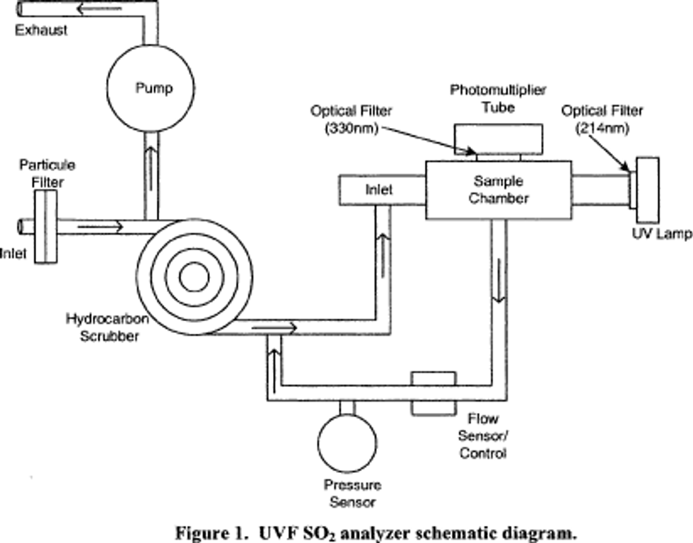
2.3 An analyzer implementing this measurement principle is shown schematically in Figure 1. Designs should include a measurement cell, a UV light source of appropriate wavelength, a UV detector system with appropriate wave length sensitivity, a pump and flow control system for sampling the ambient air and moving it into the measurement cell, sample air conditioning components as necessary to minimize measurement interferences, suitable control and measurement processing capability, and other apparatus as may be necessary. The analyzer must be designed to provide accurate, repeatable, and continuous measurements of SO2 concentrations in ambient air, with measurement performance as specified in Subpart B of Part 53 of this chapter.
2.4 Sampling considerations: The use of a particle filter on the sample inlet line of a UVF SO2 analyzer is required to prevent interference, malfunction, or damage due to particles in the sampled air.
3.0 Interferences
3.1 The effects of the principal potential interferences may need to be mitigated to meet the interference equivalent requirements of §53.11 of this chapter. Aromatic hydrocarbons such as xylene and naphthalene can fluoresce and act as strong positive interferences. These gases can be removed by using a permeation type scrubber (hydrocarbon “kicker”). Nitrogen oxide (NO) in high concentrations can also fluoresce and cause positive interference. Optical filtering can be employed to improve the rejection of interference from high NO. Ozone can absorb UV light given off by the SO2 molecule and cause a measurement offset. This effect can be reduced by minimizing the measurement path length between the area where SO2 fluorescence occurs and the photomultiplier tube detector (e.g., <5 cm). A hydrocarbon scrubber, optical filter and appropriate distancing of the measurement path length may be required method components to reduce interference.
4.0 Calibration Procedure
Atmospheres containing accurately known concentrations of sulfur dioxide are prepared using a compressed gas transfer standard diluted with accurately metered clean air flow rates.
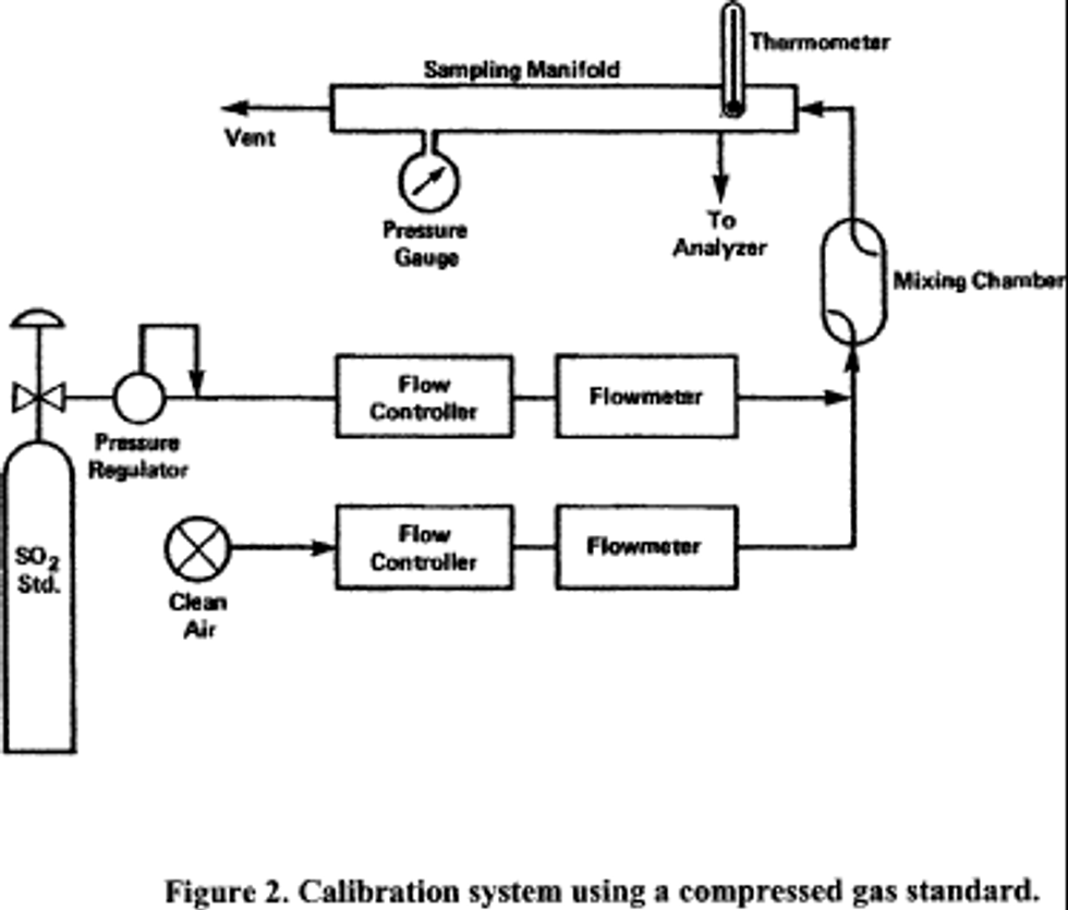
4.1 Apparatus: Figure 2 shows a typical generic system suitable for diluting a SO2 gas cylinder concentration standard with clean air through a mixing chamber to produce the desired calibration concentration standards. A valve may be used to conveniently divert the SO2 from the sampling manifold to provide clean zero air at the output manifold for zero adjustment. The system may be made up using common laboratory components, or it may be a commercially manufactured system. In either case, the principle components are as follows:
4.1.1 SO2 standard gas flow control and measurement devices (or a combined device) capable of regulating and maintaining the standard gas flow rate constant to within ±2 percent and measuring the gas flow rate accurate to within ±2, properly calibrated to a NIST-traceable standard.
4.1.2 Dilution air flow control and measurement devices (or a combined device) capable of regulating and maintaining the air flow rate constant to within ±2 percent and measuring the air flow rate accurate to within ±2, properly calibrated to a NIST-traceable standard.
4.1.3 Mixing chamber, of an inert material such as glass and of proper design to provide thorough mixing of pollutant gas and diluent air streams.
4.1.4 Sampling manifold, constructed of glass, polytetrafluoroethylene (PTFE Teflon TM), or other suitably inert material and of sufficient diameter to insure a minimum pressure drop at the analyzer connection, with a vent designed to insure a minimum over-pressure (relative to ambient air pressure) at the analyzer connection and to prevent ambient air from entering the manifold.
4.1.5 Standard gas pressure regulator, of clean stainless steel with a stainless steel diaphragm, suitable for use with a high pressure SO2 gas cylinder.
4.1.6 Reagents
4.1.6.1 SO2 gas concentration transfer standard having a certified SO2 concentration of not less than 10 ppm, in N2, traceable to a NIST Standard Reference Material (SRM).
4.1.6.2 Clean zero air, free of contaminants that could cause a detectable response or a change in sensitivity of the analyzer. Since ultraviolet fluorescence analyzers may be sensitive to aromatic hydrocarbons and O2-to-N2 ratios, it is important that the clean zero air contains less than 0.1 ppm aromatic hydrocarbons and O2 and N2 percentages approximately the same as in ambient air. A procedure for generating zero air is given in reference 1.
4.2 Procedure
4.2.1 Obtain a suitable calibration apparatus, such as the one shown schematically in Figure 1, and verify that all materials in contact with the pollutant are of glass, Teflon TM, or other suitably inert material and completely clean.
4.2.2 Purge the SO2 standard gas lines and pressure regulator to remove any residual air.
4.2.3 Ensure that there are no leaks in the system and that the flow measuring devices are properly and accurately calibrated under the conditions of use against a reliable volume or flow rate standard such as a soap-bubble meter or a wet-test meter traceable to a NIST standard. All volumetric flow rates should be corrected to the same reference temperature and pressure by using the formula below:

Where:
Fc = corrected flow rate (L/min at 25°C and 760 mm Hg),
Fm = measured flow rate, (at temperature, Tm and pressure, Pm),
Pm = measured pressure in mm Hg, (absolute), and
Tm = measured temperature in degrees Celsius.
4.2.4 Allow the SO2 analyzer under calibration to sample zero air until a stable response is obtained, then make the proper zero adjustment.
4.2.5 Adjust the airflow to provide an SO2 concentration of approximately 80 percent of the upper measurement range limit of the SO2 instrument and verify that the total air flow of the calibration system exceeds the demand of all analyzers sampling from the output manifold (with the excess vented).
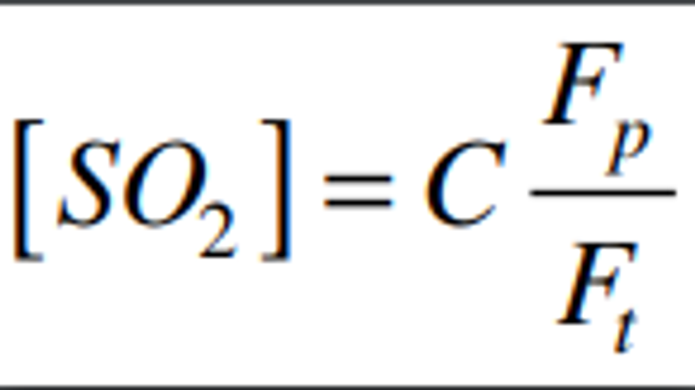
4.2.6 Calculate the actual SO2 calibration concentration standard as:

Where:
C = the concentration of the SO2 gas standard
Fp = the flow rate of SO2 gas standard
Ft = the total air flow rate of pollutant and diluent gases
4.2.7 When the analyzer response has stabilized, adjust the SO2 span control to obtain the desired response equivalent to the calculated standard concentration. If substantial adjustment of the span control is needed, it may be necessary to re-check the zero and span adjustments by repeating steps 4.2.4 through 4.2.7 until no further adjustments are needed.
4.2.8 Adjust the flow rate(s) to provide several other SO2 calibration concentrations over the analyzer's measurement range. At least five different concentrations evenly spaced throughout the analyzer's range are suggested.
4.2.9 Plot the analyzer response (vertical or Y-axis) versus SO2 concentration (horizontal or X-axis). Compute the linear regression slope and intercept and plot the regression line to verify that no point deviates from this line by more than 2 percent of the maximum concentration tested.
Note:
Additional information on calibration and pollutant standards is provided in Section 12 of Reference 3.
5.0 Frequency of Calibration
The frequency of calibration, as well as the number of points necessary to establish the calibration curve and the frequency of other performance checking will vary by analyzer; however, the minimum frequency, acceptance criteria, and subsequent actions are specified in Reference 3, Appendix D: Measurement Quality Objectives and Validation Template for SO2 (page 9 of 30). The user's quality control program should provide guidelines for initial establishment of these variables and for subsequent alteration as operational experience is accumulated. Manufacturers of analyzers should include in their instruction/operation manuals information and guidance as to these variables and on other matters of operation, calibration, routine maintenance, and quality control.
6.0 References for SO2 Method
1. H. Okabe, P. L. Splitstone, and J. J. Ball, “Ambient and Source SO2 Detector Based on a Fluorescence Method”, Journal of the Air Control Pollution Association, vol. 23, p. 514-516 (1973).
2. F. P. Schwarz, H. Okabe, and J. K. Whittaker, “Fluorescence Detection of Sulfur Dioxide in Air at the Parts per Billion Level,” Analytical Chemistry, vol. 46, pp. 1024-1028 (1974).
3. QA Handbook for Air Pollution Measurement Systems - Volume II. Ambient Air Quality Monitoring Programs. U.S.


[75 FR 35593, June 22, 2010]
['Air Programs']
['Criteria Air Pollutants', 'Air Quality']
UPGRADE TO CONTINUE READING
Load More
J. J. Keller is the trusted source for DOT / Transportation, OSHA / Workplace Safety, Human Resources, Construction Safety and Hazmat / Hazardous Materials regulation compliance products and services. J. J. Keller helps you increase safety awareness, reduce risk, follow best practices, improve safety training, and stay current with changing regulations.
Copyright 2026 J. J. Keller & Associate, Inc. For re-use options please contact copyright@jjkeller.com or call 800-558-5011.
