['Materials Handling and Storage', 'Forklifts and Powered Trucks']
['Forklifts and Powered Trucks', 'Materials Handling and Storage']
01/24/2025
...
A-1. Definitions.
The following definitions help to explain the principle of stability:
Center of gravity is the point on an object at which all of the object’s weight is concentrated. For symmetrical loads, the center of gravity is at the middle of the load.
Counterweight is the weight that is built into the truck’s basic structure and is used to offset the load’s weight and to maximize the vehicle’s resistance to tipping over.
Fulcrum is the truck’s axis of rotation when it tips over.
Grade is the slope of a surface, which is usually measured as the number of feet of rise or fall over a hundred foot horizontal distance (the slope is expressed as a percent).
Lateral stability is a truck’s resistance to overturning sideways.
Line of action is an imaginary vertical line through an object’s center of gravity.
Load center is the horizontal distance from the load’s edge (or the fork’s or other attachment’s vertical face) to the line of action through the load’s center of gravity.
Longitudinal stability is the truck’s resistance to overturning forward or rearward.
Moment is the product of the object’s weight times the distance from a fixed point (usually the fulcrum). In the case of a powered industrial truck, the distance is measured from the point at which the truck will tip over to the object’s line of action. The distance is always measured perpendicular to the line of action.
Track is the distance between the wheels on the same axle of the truck.
Wheelbase is the distance between the centerline of the vehicle’s front and rear wheels.
A-2. General.
A-2.1. Determining the stability of a powered industrial truck is simple once a few basic principles are understood. There are many factors that contribute to a vehicle’s stability: the vehicle’s wheelbase, track, and height; the load’s weight distribution; and the vehicle’s counterweight location (if the vehicle is so equipped).
A-2.2. The “stability triangle,” used in most stability discussions, demonstrates stability simply.
A-3. Basic Principles.
A-3.1. Whether an object is stable depends on the object’s moment at one end of a system being greater than, equal to, or smaller than the object’s moment at the system’s other end. This principle can be seen in the way a see-saw or teeter-totter works: that is, if the product of the load and distance from the fulcrum (moment) is equal to the moment at the device’s other end, the device is balanced and it will not move. However, if there is a greater moment at one end of the device, the device will try to move downward at the end with the greater moment.
A-3.2. The longitudinal stability of a counterbalanced powered industrial truck depends on the vehicle’s moment and the load’s moment. In other words, if the mathematic product of the load moment (the distance from the front wheels, the approximate point at which the vehicle would tip forward) to the load’s center of gravity times the load’s weight is less than the vehicle’s moment, the system is balanced and will not tip forward. However, if the load’s moment is greater than the vehicle’s moment, the greater load-moment will force the truck to tip forward.
A-4. The Stability Triangle.
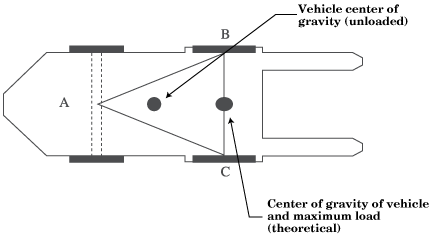
A-4.1. Almost all counterbalanced powered industrial trucks have a three-point suspension system, that is, the vehicle is supported at three points. This is true even if the vehicle has four wheels. The truck’s steer axle is attached to the truck by a pivot pin in the axle’s center. When the points are connected with imaginary lines, this three-point support forms a triangle called the stability triangle. Figure 1 depicts the stability triangle.
 |
| Figure 1 |
NOTES: 1. When the vehicle is loaded, the combined center of gravity (CG) shifts toward line B–C. Theoretically the maximum load will result in the CG at the line B–C. In actual practice, the combined CG should never be at line B–C.
2. The addition of additional counterweight will cause the truck CG to shift toward point A and result in a truck that is less stable laterally.
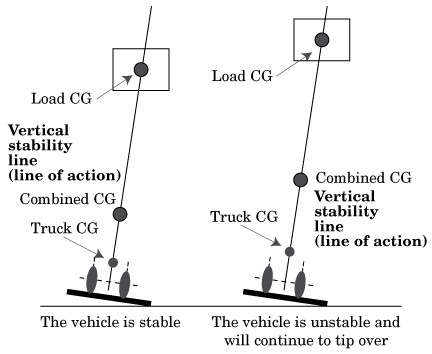
A-4.2. When the vehicle’s line of action, or load center, falls within the stability triangle, the vehicle is stable and will not tip over. However, when the vehicle’s line of action or the vehicle/load combination falls outside the stability triangle, the vehicle is unstable and may tip over. (See Figure 2.)
 |
| Figure 2 |
A-5. Longitudinal Stability.
A-5.1. The axis of rotation when a truck tips forward is the front wheels’ points of contact with the pavement. When a powered industrial truck tips forward, the truck will rotate about this line. When a truck is stable, the vehicle-moment must exceed the load-moment. As long as the vehicle-moment is equal to or exceeds the load-moment, the vehicle will not tip over. On the other hand, if the load moment slightly exceeds the vehicle-moment, the truck will begin to tip forward, thereby causing the rear to lose contact with the floor or ground and resulting in loss of steering control. If the load-moment greatly exceeds the vehicle-moment, the truck will tip forward.
A-5.2. To determine the maximum safe load-moment, the truck manufacturer normally rates the truck at a maximum load at a given distance from the front face of the forks. The specified distance from the front face of the forks to the line of action of the load is commonly called the load center. Because larger trucks normally handle loads that are physically larger, these vehicles have greater load centers. Trucks with a capacity of 30,000 pounds or less are normally rated at a given load weight at a 24-inch load center. Trucks with a capacity greater than 30,000 pounds are normally rated at a given load weight at a 36- or 48-inch load center. To safely operate the vehicle, the operator should always check the data plate to determine the maximum allowable weight at the rated load center.
A-5.3. Although the true load-moment distance is measured from the front wheels, this distance is greater than the distance from the front face of the forks. Calculating the maximum allowable load-moment using the load-center distance always provides a lower load-moment than the truck was designed to handle. When handling unusual loads, such as those that are larger than 48 inches long (the center of gravity is greater than 24 inches) or that have an offset center of gravity, etc., a maximum allowable load-moment should be calculated and used to determine whether a load can be safely handled. For example, if an operator is operating a 3,000 pound capacity truck (with a 24-inch load center), the maximum allowable load-moment is 72,000 inch-pounds (3,000 times 24). If a load is 60 inches long (30-inch load center), then the maximum that this load can weigh is 2,400 pounds (72,000 divided by 30).
A-6. Lateral Stability.
A-6.1. The vehicle’s lateral stability is determined by the line of action’s position (a vertical line that passes through the combined vehicle’s and load’s center of gravity) relative to the stability triangle. When the vehicle is not loaded, the truck’s center of gravity location is the only factor to be considered in determining the truck’s stability. As long as the line of action of the combined vehicle’s and load’s center of gravity falls within the stability triangle, the truck is stable and will not tip over. However, if the line of action falls outside the stability triangle, the truck is not stable and may tip over. Refer to Figure 2.
A-6.2. Factors that affect the vehicle’s lateral stability include the load’s placement on the truck, the height of the load above the surface on which the vehicle is operating, and the vehicle’s degree of lean.
A-7. Dynamic Stability.
A-7.1. Up to this point, the stability of a powered industrial truck has been discussed without considering the dynamic forces that result when the vehicle and load are put into motion. The weight’s transfer and the resultant shift in the center of gravity due to the dynamic forces created when the machine is moving, braking, cornering, lifting, tilting, and lowering loads, etc., are important stability considerations.
A-7.2. When determining whether a load can be safely handled, the operator should exercise extra caution when handling loads that cause the vehicle to approach its maximum design characteristics. For example, if an operator must handle a maximum load, the load should be carried at the lowest position possible, the truck should be accelerated slowly and evenly, and the forks should be tilted forward cautiously. However, no precise rules can be formulated to cover all of these eventualities.
[39 FR 23502, June 27, 1974, as amended at 40 FR 23073, May 28, 1975; 43 FR 49749, Oct. 24, 1978; 49 FR 5322, Feb. 10, 1984; 53 FR 12122, Apr. 12, 1988; 55 FR 32015, Aug 6, 1990; 61 FR 9239, Mar. 7, 1996; 63 FR 66270, Dec. 1, 1998; 68 FR 32638, June 2, 2003]
['Materials Handling and Storage', 'Forklifts and Powered Trucks']
['Forklifts and Powered Trucks', 'Materials Handling and Storage']
UPGRADE TO CONTINUE READING
Load More
J. J. Keller is the trusted source for DOT / Transportation, OSHA / Workplace Safety, Human Resources, Construction Safety and Hazmat / Hazardous Materials regulation compliance products and services. J. J. Keller helps you increase safety awareness, reduce risk, follow best practices, improve safety training, and stay current with changing regulations.
Copyright 2025 J. J. Keller & Associate, Inc. For re-use options please contact copyright@jjkeller.com or call 800-558-5011.
