Compliance Just Got Easier: Stay ahead of regulatory changes with instant notifications on updates that matter.
['Air Programs']
['Hazardous Air Pollutants']
07/08/2026

Copyright 2026 J. J. Keller & Associate, Inc. For re-use options please contact copyright@jjkeller.com or call 800-558-5011.
(a) If you have an existing affected source, you must complete all applicable performance tests within January 5, 2007, according to the provisions in §§63.7(a)(2) and 63.7114.
(b) If you have a new affected source, and commenced construction or reconstruction between December 20, 2002, and January 5, 2004, you must demonstrate initial compliance with either the proposed emission limitation or the promulgated emission limitation no later than 180 calendar days after January 5, 2004 or within 180 calendar days after startup of the source, whichever is later, according to §§63.7(a)(2)(ix) and 63.7114.
(c) If you commenced construction or reconstruction between December 20, 2002, and January 5, 2004, and you chose to comply with the proposed emission limitation when demonstrating initial compliance, you must conduct a demonstration of compliance with the promulgated emission limitation within January 5, 2007 or after startup of the source, whichever is later, according to §§63.7(a)(2)(ix) and 63.7114.
(d) For each initial compliance requirement in Table 4 to this subpart that applies to you where the monitoring averaging period is 3 hours, the 3-hour period for demonstrating continuous compliance for emission units within existing affected sources at LMP begins at 12:01 a.m. on the compliance date for existing affected sources, that is, the day following completion of the initial compliance demonstration, and ends at 3:01 a.m. on the same day.
(e) For each initial compliance requirement in Table 4 to this subpart that applies to you where the monitoring averaging period is 3 hours, the 3-hour period for demonstrating continuous compliance for emission units within new or reconstructed affected sources at LMP begins at 12:01 a.m. on the day following completion of the initial compliance demonstration, as required in paragraphs (b) and (c) of this section, and ends at 3:01 a.m. on the same day.
(f) If your affected source commenced construction or reconstruction before July 16, 2024, you must demonstrate initial compliance with the emission limitation in this subpart no later than July 16, 2027, or within 180 calendar days after startup of the source, whichever is later, according to §§63.7(a)(2)(ix) and 63.7114.
[85 FR 44978, July 24, 2020; 89 FR 57753, July 16, 2024]
You must conduct a performance test within 5 years following the initial performance test and within 5 years following each subsequent performance test thereafter.
(a) You must conduct each performance test in Table 5 to this subpart that applies to you.
(b) Prior to the relevant compliance date for your source as specified in §63.7083(e), each performance test must be conducted according to the requirements in §63.7(e)(1) and under the specific conditions specified in Table 5 to this subpart. Beginning July 16, 2024, each performance test must include the methods specified in rows 19-24 of table 5 to this subpart. On and after the relevant compliance date for your source as specified in §63.7083(e), each performance test must be conducted based on representative performance (i.e., performance based on normal operating conditions) of the affected source and under the specific conditions in Table 5 to this subpart. Representative conditions exclude periods of startup and shutdown. The owner or operator may not conduct performance tests during periods of malfunction. The owner or operator must record the process information that is necessary to document operating conditions during the test and include in such record an explanation to support that such conditions represent normal operation. Upon request, the owner or operator shall make available to the Administrator such records as may be necessary to determine the conditions of performance tests. Performance tests conducted in accordance with table 5 are not required to be performed at the same time.
(c) Prior to the relevant compliance date for your source as specified in §63.7083(e)), you may not conduct performance tests during periods of startup, shutdown, or malfunction, as specified in §63.7(e)(1)). On and after the relevant compliance date for your source as specified in §63.7083(e), you may not conduct performance tests during periods of startup, shutdown, or malfunction, as specified in paragraph (b) of this section.
(d) Except for opacity and VE observations, you must conduct three separate test runs for each performance test required in this section, as specified in §63.7(e)(3). Each test run must last at least 1 hour or as specified in table 5 to this subpart.
(e) The emission rate of particulate matter (PM) from each lime kiln (and each lime cooler if there is a separate exhaust to the atmosphere from the lime cooler) must be computed for each run using Equation 1 of this section:

Where:
E = Emission rate of PM, pounds per ton (lb/ton) of stone feed.
Ck = Concentration of PM in the kiln effluent, grain/dry standard cubic feet (gr/dscf).
Qk = Volumetric flow rate of kiln effluent gas, dry standard cubic feet per hour (dscf/hr).
Cc = Concentration of PM in the cooler effluent, grain/dscf. This value is zero if there is not a separate cooler exhaust to the atmosphere.
Qc = Volumetric flow rate of cooler effluent gas, dscf/hr. This value is zero if there is not a separate cooler exhaust to the atmosphere.
P = Stone feed rate, tons per hour (ton/hr).
K = Conversion factor, 7000 grains per pound (grains/lb).
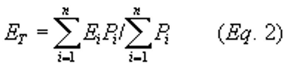
(f)(1) If you choose to meet a weighted average emission limit as specified in item 4 of Table 1 to this subpart, you must calculate a combined particulate emission rate from all kilns and coolers within your LMP using Equation 2 of this section:
Where:
ET = Emission rate of PM from all kilns and coolers, lb/ton of stone feed.
Ei = Emission rate of PM from kiln i, or from kiln/cooler combination i, lb/ton of stone feed.
Pi = Stone feed rate to kiln i, ton/hr.
n = Number of kilns you wish to include in averaging.
(2) You do not have to include every kiln in this calculation, only include kilns you wish to average. Kilns that have a PM emission limit of 0.60 lb/tsf are ineligible for any averaging.
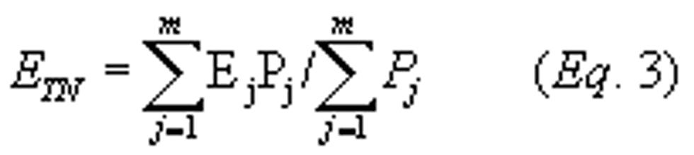
(g) The weighted average PM emission limit from all kilns and coolers for which you are averaging must be calculated using Equation 3 of this section:
Where:
ETN = Weighted average PM emission limit for all kilns and coolers being included in averaging at the LMP, lb/ton of stone feed.
Ej = PM emission limit (0.10 or 0.12) for kiln j, or for kiln/cooler combination j, lb/ton of stone feed.
Pj = Stone feed rate to kiln j, ton/hr.
m = Number of kilns and kiln/cooler combinations you are averaging at your LMP. You must include the same kilns in the calculation of ET and ETN. Kilns that have a PM emission limit of 0.60 lb/tsf are ineligible for any averaging.
(h) Performance test results must be documented in complete test reports that contain the information required by paragraphs (h)(1) through (10) of this section, as well as all other relevant information. The plan to be followed during testing must be made available to the Administrator at least 60 days prior to testing.
(1) A brief description of the process and the air pollution control system;
(2) Sampling location description(s);
(3) A description of sampling and analytical procedures and any modifications to standard procedures;
(4) Test results, including opacity;
(5) Quality assurance procedures and results;
(6) Records of operating conditions during the test, preparation of standards, and calibration procedures;
(7) Raw data sheets for field sampling and field and laboratory analyses;
(8) Documentation of calculations;
(9) All data recorded and used to establish operating limits; and
(10) Any other information required by the test method.
(i) [Reserved]
(j) You must establish any applicable 3-hour block average operating limit indicated in Table 3 to this subpart according to the applicable requirements in Table 4 to this subpart and paragraphs (j)(1) through (4) of this section.
(1) Continuously record the parameter during the performance test and include the parameter record(s) in the performance test report.
(2) Determine the average parameter value for each 15-minute period of each test run.
(3) Calculate the test run average for the parameter by taking the average of all the 15-minute parameter values for the run.
(4) Calculate the 3-hour operating limit by taking the average of the three test run averages.
(k) For each building enclosing any PSH operations that is subject to a VE limit, you must conduct a VE check according to item 18 in Table 5 to this subpart, and in accordance with paragraphs (k)(1) through (3) of this section.
(1) Conduct visual inspections that consist of a visual survey of the building over the test period to identify if there are VE, other than condensed water vapor.
(2) Select a position at least 15 but not more 1,320 feet from each side of the building with the sun or other light source generally at your back.
(3) The observer conducting the VE checks need not be certified to conduct EPA Method 9 in appendix A-4 to part 60 of this chapter. However, the observer must meet the training requirements as described in EPA Method 22 in appendix A-7 to part 60 of this chapter.
(l) When determining compliance with the opacity standards for fugitive emissions from PSH operations in item 8 of Table 1 to this subpart, you must conduct EPA Method 9 in appendix A-4 to part 60 of this chapter according to item 17 in Table 5 to this subpart, and in accordance with paragraphs (l)(1) through (3) of this section.
(1) The minimum distance between the observer and the emission source shall be 4.57 meters (15 feet).
(2) The observer shall, when possible, select a position that minimizes interference from other fugitive emission sources (e.g., road dust). The required observer position relative to the sun must be followed.
(3) If you use wet dust suppression to control PM from PSH operations, a visible mist is sometimes generated by the spray. The water mist must not be confused with particulate matter emissions and is not to be considered VE. When a water mist of this nature is present, you must observe emissions at a point in the plume where the mist is no longer visible.
(m) On and after the relevant compliance date for your source as specified in §63.7083(e), during startup, kilns must be tested hourly to determine when lime product meets the definition of on-specification lime product.
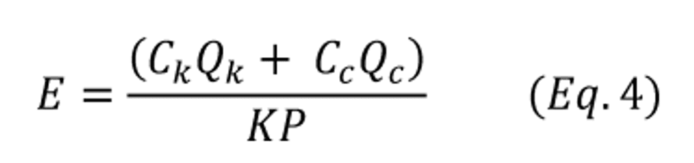
(n) The emission rate of mercury and hydrogen chloride (HCl) from each lime kiln (and each lime cooler as applicable) must be computed for each run using equation 4 to this paragraph (n):
Equation 4 to Paragraph (n)
Where:
E = Emission rate of mercury, pounds per thousand tons (lb/MMton) of lime produced or HCl pounds per ton (lb/ton) of lime produced.
Ck = Concentration in the kiln effluent of mercury, micrograms/dry standard cubic feet (µg/dscf) or HCl, parts per million by volume on a dry basis (ppmvd).
Qk = Volumetric flow rate of kiln effluent gas, dry standard cubic feet per hour (dscf/hr).
Cc = Concentration in the cooler effluent of mercury, µg/dscf or HCl, ppmvd. This value is zero if there is not a separate cooler exhaust to the atmosphere.
Qc = Volumetric flow rate of cooler effluent gas, dscf/hr. This value is zero if there is not a separate cooler exhaust to the atmosphere.
P = Lime production rate, tons per hour (ton/hr).
K = Conversion factor, for mercury, 4.4x10⁸ micrograms per pound (µg/lb) for HCL 1.09x10⁷ ppmvd HCl per lb/dscf HCl.
(o) The concentration of total hydrocarbons and dioxins/furans shall be correct to 7 percent oxygen using equation 5 to this paragraph (o):
Equation 5 to Paragraph (o)

Where:
C7% = concentration of total hydrocarbons ppmv as propane on a dry basis or dioxins/furans in ng/dscm corrected to 7 percent oxygen.
Cunc = uncorrected total hydrocarbon concentration, ppmv as propane on a dry basis or dioxins/furans in ng/dscm.
CO2 = concentration of oxygen (percent).
[85 FR 44978, July 24, 2020; 89 FR 57753, July 16, 2024]
(a) You must install, operate, and maintain each continuous parameter monitoring system (CPMS) according to your OM&M plan required by §63.7100(d) and paragraphs (a)(1) through (5) of this section, and you must install, operate, and maintain each continuous opacity monitoring system (COMS) as required by paragraph (g) of this section
(1) The CPMS must complete a minimum of one cycle of operation for each successive 15-minute period.
(2) To calculate a valid hourly value, you must have at least four equally spaced data values (or at least two, if that condition is included to allow for periodic calibration checks) for that hour from a CPMS that is not out of control according your OM&M plan, and use all valid data.
(3) To calculate the average for each 3-hour block averaging period, you must use all valid data, and you must have at least 66 percent of the hourly averages for that period using only hourly average values that are based on valid data (i.e., not from out-of-control periods).
(4) You must conduct a performance evaluation of each CPMS in accordance with your OM&M plan.
(5) You must continuously operate and maintain the CPMS according to the OM&M plan, including, but not limited to, maintaining necessary parts for routine repairs of the monitoring equipment.
(b) For each flow measurement device, you must meet the requirements in paragraphs (a)(1) through (5) and (b)(1) through (4) of this section.
(1) Use a flow sensor with a minimum tolerance of 2 percent of the flow rate.
(2) Reduce swirling flow or abnormal velocity distributions due to upstream and downstream disturbances.
(3) Conduct a flow sensor calibration check at least semiannually.
(4) At least monthly, inspect all components for integrity, all electrical connections for continuity, and all mechanical connections for leakage.
(c) For each pressure measurement device, you must meet the requirements in paragraphs (a)(1) through (5) and (c)(1) through (7) of this section.
(1) Locate the pressure sensor(s) in or as close to as possible a position that provides a representative measurement of the pressure.
(2) Minimize or eliminate pulsating pressure, vibration, and internal and external corrosion.
(3) Use a gauge with a minimum tolerance of 0.5 inch of water or a transducer with a minimum tolerance of 1 percent of the pressure range.
(4) Check pressure tap pluggage daily.
(5) Using a manometer, check gauge calibration quarterly and transducer calibration monthly.
(6) Conduct calibration checks any time the sensor exceeds the manufacturer's specified maximum operating pressure range or install a new pressure sensor.
(7) At least monthly, inspect all components for integrity, all electrical connections for continuity, and all mechanical connections for leakage.
(d) For each bag leak detection system (BLDS), you must meet any applicable requirements in paragraphs (a)(1) through (5) and (d)(1) through (10) of this section.
(1) The BLDS must be certified by the manufacturer to be capable of detecting PM emissions at concentrations of 10 milligrams per actual cubic meter (0.0044 grains per actual cubic foot) or less.
(2) The sensor on the BLDS must provide output of relative PM emissions.
(3) The BLDS must be equipped with a device to continuously record the output signal from the sensor.
(4) The BLDS must have an alarm that will sound automatically when it detects an increase in relative PM emissions greater than a preset level.
(5) The alarm must be located in an area where appropriate plant personnel will be able to hear it.
(6) For a positive-pressure fabric filter (FF), each compartment or cell must have a bag leak detector (BLD). For a negative-pressure or induced-air FF, the BLD must be installed downstream of the FF. If multiple BLD are required (for either type of FF), the detectors may share the system instrumentation and alarm.
(7) Each triboelectric BLDS must be installed, calibrated, operated, and maintained according to EPA-454/R-98-015, “Fabric Filter Bag Leak Detection Guidance,” (incorporated by reference—see §63.14). Other types of bag leak detection systems must be installed, operated, calibrated, and maintained according to the manufacturer's written specifications and recommendations. Standard operating procedures must be incorporated into the OM&M plan.
(8) At a minimum, initial adjustment of the system must consist of establishing the baseline output in both of the following ways, according to section 5.0 of the EPA-454/R-98-015, “Fabric Filter Bag Leak Detection Guidance,” (incorporated by reference—see §63.14):
(i) Adjust the range and the averaging period of the device.
(ii) Establish the alarm set points and the alarm delay time.
(9) After initial adjustment, the sensitivity or range, averaging period, alarm set points, or alarm delay time may not be adjusted except as specified in the OM&M plan required by §63.7100(d). In no event may the range be increased by more than 100 percent or decreased by more than 50 percent over a 365-day period unless such adjustment follows a complete FF inspection that demonstrates that the FF is in good operating condition, as defined in section 5.2 of the “Fabric Filter Bag Leak Detection Guidance,” (incorporated by reference—see §63.14). Record each adjustment.
(10) Record the results of each inspection, calibration, and validation check.
(e) For each PM detector, you must meet any applicable requirements in paragraphs (a)(1) through (5) and (e)(1) through (8) of this section.
(1) The PM detector must be certified by the manufacturer to be capable of detecting PM emissions at concentrations of 10 milligrams per actual cubic meter (0.0044 grains per actual cubic foot) or less.
(2) The sensor on the PM detector must provide output of relative PM emissions.
(3) The PM detector must have an alarm that will sound automatically when it detects an increase in relative PM emissions greater than a preset level.
(4) The alarm must be located in an area where appropriate plant personnel will be able to hear it.
(5) For a positive-pressure electrostatic precipitator (ESP), each compartment must have a PM detector. For a negative-pressure or induced-air ESP, the PM detector must be installed downstream of the ESP. If multiple PM detectors are required (for either type of ESP), the detectors may share the system instrumentation and alarm.
(6) Particulate matter detectors must be installed, operated, adjusted, and maintained according to the manufacturer's written specifications and recommendations. Standard operating procedures must be incorporated into the OM&M plan.
(7) At a minimum, initial adjustment of the system must consist of establishing the baseline output in both of the following ways:
(i) Adjust the range and the averaging period of the device.
(ii) Establish the alarm set points and the alarm delay time.
(8) After initial adjustment, the range, averaging period, alarm set points, or alarm delay time may not be adjusted except as specified in the OM&M plan required by §63.7100(d). In no event may the range be increased by more than 100 percent or decreased by more than 50 percent over a 365-day period unless a responsible official as defined in §63.2 certifies in writing to the Administrator that the ESP has been inspected and found to be in good operating condition.
(f) For each emission unit equipped with an add-on air pollution control device, you must inspect each capture/collection and closed vent system at least once each calendar year to ensure that each system is operating in accordance with the operating requirements in item 6 of Table 3 to this subpart and record the results of each inspection.
(g) For each COMS used to monitor an add-on air pollution control device, you must meet the requirements in paragraphs (g)(1) and (2) of this section.
(1) Install the COMS at the outlet of the control device.
(2) Install, maintain, calibrate, and operate the COMS as required by 40 CFR part 63, subpart A, General Provisions and according to Performance Specification (PS)-1 of appendix B to part 60 of this chapter. Facilities that operate COMS installed on or before February 6, 2001, may continue to meet the requirements in effect at the time of COMS installation unless specifically required to re-certify the COMS by their permitting authority.
(h) For each mass flow rate monitor used for measuring the dry sorbent injection rate (e.g., sorbent, activated carbon, etc.) you must meet the requirements of (h)(1) through (3) of this section.
(1) Locate the device in a position(s) that provides a representative measurement of the total sorbent injection rate.
(2) Install and calibrate the device in accordance with manufacturer's procedures and specifications.
(3) At least annually, calibrate the device in accordance with the manufacturer's procedures and specifications.
(i) For each temperature monitoring device installed to monitor the temperature of a thermal oxidizer, you must meet the requirements of (i)(1) through (3) of this section.
(1) Install the temperature monitoring device in the fire box or in the ductwork immediately downstream of the fire box in a position before any substantial heat exchange occurs.
(2) The temperature measurement system must be capable of measuring the temperature over a range that extends at least 20 percent beyond the normal expected operating range and has an accuracy of ±1 percent of temperature measured or 2.8 degrees Celsius (5 degrees Fahrenheit) whichever is greater. The data recording system associated with affected CPMS must have a resolution that is equal to or better than one-half of the required system accuracy.
(3) The calibration reference for the temperature measurement must be a National Institute of Standards and Technology (NIST) calibrated reference thermocouple-potentiometer system, NIST traceable certified reference thermocouple, or alternate reference, subject to approval by the Administrator.
(4) The calibration of all thermocouples and other temperature sensors must be verified at least once every three months.
[85 FR 44978, July 24, 2020; 89 FR 57754, July 16, 2024]
(a) You must demonstrate initial compliance with each emission limit in Table 1 to this subpart that applies to you, according to Table 4 to this subpart. For existing lime kilns and their associated coolers, you may perform VE measurements in accordance with EPA Method 9 of appendix A to part 60 in lieu of installing a COMS or PM detector if any of the conditions in paragraphs (a)(1) through (3) of this section exist:
(1) You use a FF for PM control, and the FF is under positive pressure and has multiple stacks; or
(2) The control device exhausts through a monovent; or
(3) The installation of a COMS in accordance with PS-1 of appendix B to part 60 is infeasible.
(b) For those LMP that comply with either the HCl emissions limit or the mercury emission limit using emissions averaging, the average HCl or mercury emissions determined according to the procedures in §63.7112(n), must not exceed the applicable emission limit in table 9 to this subpart.
(c) For those LMP that comply with either the HCl emissions limit or the mercury emission limit using emissions averaging, you must comply with the requirements in paragraphs (c)(1) through (4) of this section.
(1) You must complete the stack testing required in paragraph §63.7112(n) for all lime kilns you wish to include in the emission average before submitting the implementation plan required in paragraph (c)(2) of this section.
(2) You must develop and submit to the applicable regulatory authority for review and approval, an implementation plan for emission averaging no later than 180 days before the date you intend to demonstrate compliance using the emission averaging option. You must include the information contained in paragraphs (c)(2)(i) through (iii) of this section in your implementation plan.
(i) Identification of all lime kilns in the averaging group, including the lime kiln subcategory, type of lime produced, typical stone production rate, control technology installed, and types of fuel(s) that will be burned.
(ii) The HCl or mercury emission rate for each lime kiln for each of the fuels identified in paragraph (c)(2)(i) of this section.
(iii) The date on which you are requesting emission averaging to commence.
(3) The regulatory authority shall review and approve or disapprove the plan according to the following criteria:
(i) Whether the content of the plan includes all the information specified in paragraph (c)(2) of this section; and
(ii) Whether the plan presents sufficient information to determine that compliance will be achieved and maintained.
(4) The applicable regulatory authority shall not approve an emission averaging implementation plan containing any of the following provisions:
(i) Averaging between emissions of differing pollutants;
(ii) Averaging that includes lime kilns constructed or reconstructed on or after July 16, 2024; or
(iii) Averaging between lime kilns located at different facilities.
(iv) Averaging between lime kilns in different subcategories.
(d) You must establish each site-specific operating limit in Table 3 to this subpart that applies to you according to the requirements in §63.7112(j) and Table 5 to this subpart. Alternative parameters may be monitored if approval is obtained according to the procedures in §63.8(f).
(e) You must submit the Notification of Compliance Status containing the results of the initial compliance demonstration according to the requirements in §63.7130(e).
[85 FR 44979, July 24, 2020; 89 FR 57754, July 16, 2024]
['Air Programs']
['Hazardous Air Pollutants']
UPGRADE TO CONTINUE READING
ezExplanations
Results Aided by AI