['Air Programs']
['Air Emissions']
03/21/2023
...
(a) Ambient conditions. Dynamometer testing under this part generally requires that you maintain the test cell within a specified range of ambient temperature and humidity. Use good engineering judgment to maintain relatively uniform temperatures throughout the test cell before testing. You are generally not required to maintain uniform temperatures throughout the test cell while the vehicle is running due to the heat generated by the vehicle. Measured humidity values must represent the conditions to which the vehicle is exposed, which includes intake air; other than the intake air, humidity does not affect emissions, so humidity need not be uniform throughout the test cell.
(b) General requirements for cooling fans. Use good engineering judgment to select and configure fans to cool the test vehicle in a way that meets the specifications of paragraph (c) of this section and simulates in-use operation. If you demonstrate that the specified fan configuration is impractical for special vehicle designs, such as vehicles with rear-mounted engines, or it does not provide adequate cooling to properly represent in-use operation, you may ask us to approve increasing fan capacity or using additional fans.
(c) Allowable cooling fans for vehicles at or below 14,000 pounds GVWR. Cooling fan specifications for vehicles at or below 14,000 pounds GVWR depend on the test cycle. Paragraph (c)(1) of this section summarizes the cooling fan specifications for the different test cycles; the detailed specifications are described in paragraphs (c)(2) through (5) of this section. See �1066.410 for instruction regarding how to use the fans during testing.
(1) Cooling fan specifications for different test cycles are summarized as follows:
(i) For the FTP test cycle, the allowable cooling fan configurations are described in paragraphs (c)(2) and (3) of this section.
(ii) For the HFET test cycle, the allowable cooling fan configurations are described in paragraphs (c)(2) and (3) of this section.
(iii) For the US06 test cycle, the allowable cooling fan configurations are described in paragraphs (c)(2) and (4) of this section.
(iv) For the LA-92 test cycle, the allowable cooling fan configurations are described in paragraphs (c)(2) and (4) of this section.
(v) For SC03 and AC17 test cycles, the allowable cooling fan configuration is described in paragraph (c)(5) of this section.
(2) You may use a road-speed modulated fan system meeting the specifications of this paragraph (c)(2) for anything other than SC03 and AC17 testing. Use a road-speed modulated fan that achieves a linear speed of cooling air at the blower outlet that is within �3.0 mi/hr (�1.3 m/s) of the corresponding roll speed when vehicle speeds are between 5 and 30 mi/hr, and within �6.5 mi/hr (�2.9 m/s) of the corresponding roll speed at higher vehicle speeds; however you may limit the fan's maximum linear speed to 70 mi/hr. We recommend that the cooling fan have a minimum opening of 0.2 m 2 and a minimum width of 0.8 m.
(i) Verify the air flow velocity for fan speeds corresponding to vehicle speeds of 20 and 40 mi/hr using an instrument that has an accuracy of �2% of the measured air flow speed.
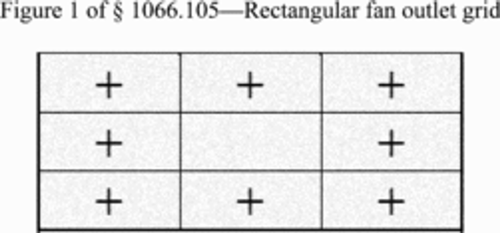
(ii) For fans with rectangular outlets, divide the fan outlet into sections as shown in Figure 1 of this section. As illustrated by the � + � in the following figure, measure flow from the center of each section; do not measure the flow from the center section.

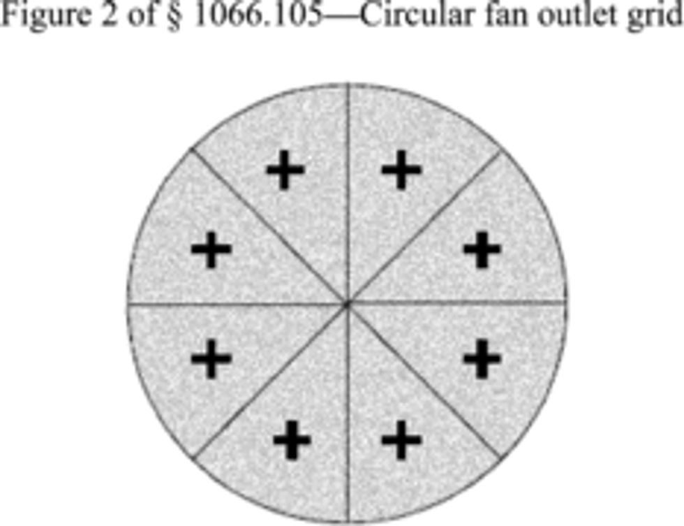
(iii) For fans with circular outlets, divide the fan outlet into 8 equal sections as shown in Figure 2 of this section. As illustrated by the � + � in the following figure, measure flow on the radial centerline of each section, at a radius of two-thirds of the fan's total radius.

(iv) Verify that the uniformity of the fan's axial flow is constant across the discharge area within a tolerance of �4.0 mi/hr of the vehicle's speed at fan speeds corresponding to 20 mi/hr, and within �8.0 mi/hr at fan speeds corresponding to 40 mi/hr. For example, at a vehicle speed of 20.2 mi/hr, axial flow at all locations denoted by the �+� across the discharge nozzle must be between 16.2 and 24.2 mi/hr. When measuring the axial air flow velocity, use good engineering judgment to determine the distance from the nozzle outlet at each point of the fan outlet grid. Use these values to calculate a mean air flow velocity across the discharge area at each speed setting. The instrument used to verify the air velocity must have an accuracy of �2% of the measured air flow velocity.
(v) Use a multi-axis flow meter or another method to verify that the fan's air flow perpendicular to the axial air flow is less than 15% of the axial air flow, consistent with good engineering judgment. Demonstrate this by comparing the perpendicular air flow velocity to the mean air flow velocities determined in paragraph (c)(2)(iv) of this section at vehicle speeds of 20 and 40 mi/hr.
(3) You may use a fixed-speed fan with a maximum capacity up to 2.50 m 3/s for FTP and HFET testing.
(4) You may use a fixed-speed fan with a maximum capacity up to 7.10 m 3/s for US06 and LA-92 testing.
(5) For SC03 and AC17 testing, use a road-speed modulated fan with a minimum discharge area that is equal to or exceeds the vehicle's frontal inlet area. We recommend using a fan with a discharge area of 1.7 m 2.
(i) Air flow volumes must be proportional to vehicle speed. Select a fan size that will produce a flow volume of approximately 45 m 3/s at 60 mi/hr. If this fan is also the only source of test cell air circulation or if fan operational mechanics make the 0 mi/hr air flow requirement impractical, air flow of 2 mi/hr or less at 0 mi/hr vehicle speed is allowed.
(ii) Verify the uniformity of the fan's axial flow as described in paragraph (c)(2)(iv) of this section, except that you must measure the axial air flow velocity 60 cm from the nozzle outlet at each point of the discharge area grid.
(iii) Use a multi-axis flow meter or another method to verify that the fan's air flow perpendicular to the axial air flow is less than 10% of the axial air flow, consistent with good engineering judgment. Demonstrate this by comparing the perpendicular air flow velocity to the mean air flow velocities determined in paragraph (c)(2)(iv) of this section at vehicle speeds of 20 and 40 mi/hr.
(iv) In addition to the road-speed modulated fan, we may approve the use of one or more fixed-speed fans to provide proper cooling to represent in-use operation, but only up to a total of 2.50 m 3/s for all additional fans.
(d) Allowable cooling fans for vehicles above 14,000 pounds GVWR. For all testing, use a road-speed modulated fan system that achieves a linear speed of cooling air at the blower outlet that is within �3.0 mi/hr (�1.3 m/s) of the corresponding roll speed when vehicle speeds are between 5 and 30 mi/hr, and within �10 mi/hr (�4.5 m/s) of the corresponding roll speed at higher vehicle speeds. For vehicles above 19,500 pounds GVWR, we recommend that the cooling fan have a minimum opening of 2.75 m 2, a minimum flow rate of 60 m 3/s at a fan speed of 50 mi/hr, and a minimum speed profile in the free stream flow, across the duct that is �15% of the target flow rate.
[79 FR 23823, Apr. 28, 2014, as amended at 81 FR 74195, Oct. 25, 2016]
['Air Programs']
['Air Emissions']
UPGRADE TO CONTINUE READING
Load More
J. J. Keller is the trusted source for DOT / Transportation, OSHA / Workplace Safety, Human Resources, Construction Safety and Hazmat / Hazardous Materials regulation compliance products and services. J. J. Keller helps you increase safety awareness, reduce risk, follow best practices, improve safety training, and stay current with changing regulations.
Copyright 2025 J. J. Keller & Associate, Inc. For re-use options please contact copyright@jjkeller.com or call 800-558-5011.
