['Air Programs']
['Air Emissions']
07/19/2024
...
(a) This optional carbon balance error verification compares independently calculated quantities of carbon flowing into and out of an engine system. The engine system includes aftertreatment devices as applicable. Calculating carbon intake considers carbon-carrying streams flowing into the system, including intake air, fuel, and optionally DEF or other fluids. Carbon flow out of the system comes from exhaust emission calculations. Note that this verification is not valid if you calculate exhaust molar flow rate using fuel rate and chemical balance as described in §1065.655(f)(3) because carbon flows into and out of the system are not independent. Use good engineering judgment to ensure that carbon mass in and carbon mass out data signals align.
(b) Perform the carbon balance error verification after emission sampling is complete for a test sequence as described in §1065.530(g)(5). Testing must include measured values as needed to determine intake air, fuel flow, and carbon-related gaseous exhaust emissions. You may optionally account for the flow of carbon-carrying fluids other than intake air and fuel into the system. Perform carbon balance error verification as follows:
(1) Calculate carbon balance error quantities as described in §1065.643. The three quantities for individual test intervals are carbon mass absolute error, ε aC , carbon mass rate absolute error, ε aCrate , and carbon mass relative error, ε rC . Determine ε aC , ε aCrate , and ε rC for all test intervals. You may determine composite carbon mass relative error, ε rCcomp , as a fourth quantity that optionally applies for duty cycles with multiple test intervals.
(2) You meet the carbon balance error verification for a test sequence if all test intervals pass the test-interval criteria. A test interval passes if at least one of the absolute values of the three carbon balance error quantities for test intervals, ε aC , ε aCrate , and ε rC , is at or below its respective limit value in paragraphs (b)(2)(i) through (iii) of this section. You meet the carbon balance error verification for a duty cycle with multiple test intervals if the duty cycle passes the duty-cycle criterion. A duty cycle passes if the absolute value of the composite carbon mass relative error quantity, ε rCcomp , is at or below the limit value in paragraph (b)(2)(iii) of this section. Unless specified otherwise in the standard-setting part, if verification fails for a test sequence, you may repeat the entire test sequence or repeat individual test intervals as described in §1065.526.
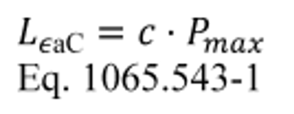
(i) Calculate the carbon mass absolute error limit, L aC , in grams to three decimal places for comparison to the absolute value of aC , using the following equation:

Where:
c = power-specific carbon mass absolute error coefficient = 0.007 g/kW.
P max = maximum power from the engine map generated according to §1065.510. If measured P max is not available, use a manufacturer-declared value for P max .
Example:
c = 0.007 g/kW
P max = 230.0 kW
L aC = 0.007 · 230.0
L aC = 1.610 g
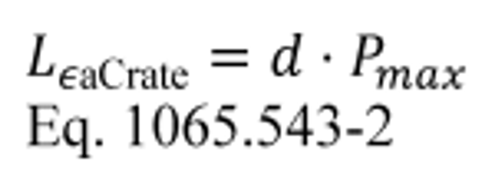
(ii) Calculate the carbon mass rate absolute error limit, L , in grams per hour to three decimal places for comparison to the absolute value of ε aCrate , using the following equation:

Where:
d = power-specific carbon mass rate absolute error coefficient = 0.31 g/(kW·hr).
P max = maximum power from the engine map generated according to §1065.510. If measured P max is not available, use a manufacturer-declared value for P max .
Example:
d = 0.31 g/(kW·hr)
P max = 230.0 kW
L aCrate = 0.31.230.0
L aCrate = 71.300 g/hr
(iii) The carbon mass relative error limit, L rC , is 0.020 for comparison to the absolute value of ε rC , and to the absolute value of ε rCcomp .
(c) A failed carbon balance error verification might indicate one or more problems requiring corrective action, as follows:
| Area of concern | Problem | Recommended corrective action |
|---|---|---|
| Gas analyzer system | Incorrect analyzer calibration | Calibrate NDIR and THC analyzers. |
| Incorrect time alignment between flow and concentration data | Determine transformation time, t50, for continuous gas analyzers and time-align flow and concentration data as described in §1065.650(c)(2)(i). | |
| Problems with the sample system | Inspect sample system components such as sample lines, filters, chillers, and pumps for leaks, operating temperature, and contamination. | |
| Fuel flow measurement | Zero shift of fuel flow rate meter | Perform an in-situ zero adjustment. |
| Change in fuel flow meter calibration | Calibrate the fuel flow meter as described in §1065.320. | |
| Incorrect time alignment of fuel flow data | Verify alignment of carbon mass in and carbon mass out data streams. | |
| Short sampling periods | For test intervals with varying duration, such as discrete-mode steady-state duty cycles, make the test intervals longer to improve accuracy when measuring low fuel flow rates. | |
| Fluctuations in the fuel conditioning system | Improve stability of the fuel temperature and pressure conditioning system to improve accuracy when measuring low fuel flow rates. | |
| Dilute testing using a CVS system | Leaks | Inspect exhaust system and CVS tunnel, connections, and fasteners. Repair or replace components as needed. A leak in the exhaust transfer tube to the CVS may result in negative values for carbon balance error. |
| Poor mixing | Perform the verification related to mixing in §1065.341(f). | |
| Change in CVS calibration | Calibrate the CVS flow meter as described in §1065.340. | |
| Flow meter entrance effects | Inspect the CVS tunnel to determine whether entrance effects from the piping configuration upstream of the flow meter adversely affect flow measurement. | |
| Other problems with the CVS or sampling verification hardware or software | Inspect hardware and software for the CVS system and CVS verification system for discrepancies. | |
| Raw testing using intake air flow measurement or direct exhaust flow measurement | Leaks | Inspect intake air and exhaust systems, connections, fasteners. Repair or replace components as needed. |
| Zero shift of intake air flow rate meter | Perform an in-situ zero adjustment. | |
| Change in intake air flow meter calibration | Calibrate the intake air flow meter as described in §1065.325. | |
| Zero shift of exhaust flow rate meter | Perform an in-situ zero adjustment. | |
| Change in exhaust flow meter calibration | Calibrate the exhaust flow meter as described in §1065.330. | |
| Flow meter entrance effects | Inspect intake air and exhaust systems to determine whether entrance effects from the piping configuration upstream and downstream of the intake air flow meter or the exhaust flow meter adversely affect flow measurement. | |
| Other problems with the intake air flow and exhaust flow measurement hardware or software | Look for discrepancies in the hardware and software for measuring intake air flow and exhaust flow. | |
| Poor mixing | Ensure that all streams are well mixed. | |
| Accuracy of fluid properties | Inaccurate fluid properties | If defaults are used, use measured values. If measured values are used, verify fluid property determination. |
[86 FR 34547, Jun. 29, 2021; 87 FR 65865, Oct. 26, 2022; 88 FR 4679, Jan. 24, 2023]
['Air Programs']
['Air Emissions']
UPGRADE TO CONTINUE READING
Load More
J. J. Keller is the trusted source for DOT / Transportation, OSHA / Workplace Safety, Human Resources, Construction Safety and Hazmat / Hazardous Materials regulation compliance products and services. J. J. Keller helps you increase safety awareness, reduce risk, follow best practices, improve safety training, and stay current with changing regulations.
Copyright 2026 J. J. Keller & Associate, Inc. For re-use options please contact copyright@jjkeller.com or call 800-558-5011.
