...
This section describes the procedure to measure fuel consumption and create engine fuel maps by testing a powertrain that includes an engine coupled with a transmission, drive axle, and hybrid components or any assembly with one or more of those hardware elements. Engine fuel maps are part of demonstrating compliance with Phase 2 and Phase 3 vehicle standards under 40 CFR part 1037; the powertrain test procedure in this section is one option for generating this fuel-mapping information as described in §1036.505. Additionally, this powertrain test procedure is one option for certifying hybrid powertrains to the engine standards in §§1036.104 and 1036.108.
(a) General test provisions. The following provisions apply broadly for testing under this section:
(1) Measure NO X emissions as described in paragraph (k) of this section. Include these measured NO X values any time you report to us your greenhouse gas emissions or fuel consumption values from testing under this section.
(2) The procedures of 40 CFR part 1065 apply for testing in this section except as specified. This section uses engine parameters and variables that are consistent with 40 CFR part 1065.
(3) Powertrain testing depends on models to calculate certain parameters. You can use the detailed equations in this section to create your own models, or use the GEM HIL model contained within GEM Phase 2, Version 4.0 (incorporated by reference, see §1036.810) to simulate vehicle hardware elements as follows:
(i) Create driveline and vehicle models that calculate the angular speed setpoint for the test cell dynamometer, f nref,dyno, based on the torque measurement location. Use the detailed equations in paragraph (f) of this section, the GEM HIL model's driveline and vehicle submodels, or a combination of the equations and the submodels. You may use the GEM HIL model's transmission submodel in paragraph (f) to simulate a transmission only if testing hybrid engines. If the engine is intended for vehicles with automatic transmissions, use the cycle configuration file in GEM to change the transmission state (in-gear or idle) as a function of time as defined by the duty cycles in this part.
(ii) Create a driver model or use the GEM HIL model's driver submodel to simulate a human driver modulating the throttle and brake pedals to follow the test cycle as closely as possible.
(iii) Create a cycle-interpolation model or use the GEM HIL model's cycle submodel to interpolate the duty-cycles and feed the driver model the duty-cycle reference vehicle speed for each point in the duty-cycle.
(4) The powertrain test procedure in this section is designed to simulate operation of different vehicle configurations over specific duty cycles. See paragraphs (h) and (j) of this section.
(5) For each test run, record engine speed and torque as defined in 40 CFR 1065.915(d)(5) with a minimum sampling frequency of 1 Hz. These engine speed and torque values represent a duty cycle that can be used for separate testing with an engine mounted on an engine dynamometer under 40 CFR 1037.551, such as for a selective enforcement audit as described in 40 CFR 1037.301.
(6) For hybrid powertrains with no plug-in capability, correct for the net energy change of the energy storage device as described in 40 CFR 1066.501(a)(3). For plug-in hybrid electric powertrains, follow 40 CFR 1066.501(a)(3) to determine End-of-Test for charge-depleting operation. You must get our approval in advance for your utility factor curve; we will approve it if you can show that you created it, using good engineering judgment, from sufficient in-use data of vehicles in the same application as the vehicles in which the plug-in hybrid electric powertrain will be installed. You may use methodologies described in SAE J2841 to develop the utility factor curve.
(7) The provisions related to carbon balance error verification in §1036.543 apply for all testing in this section. These procedures are optional if you are only performing direct or indirect fuel-flow measurement, but we will perform carbon balance error verification for all testing under this section.
(8) Do not apply accessory loads when conducting a powertrain test to generate inputs to GEM if torque is measured at the axle input shaft or wheel hubs.
(9) If you test a powertrain over the Low Load Cycle specified in §1036.514, control and apply the electrical accessory loads. We recommend using a load bank connected directly to the powertrain's electrical system. You may instead use an alternator with dynamic electrical load control. Use good engineering judgment to account for the efficiency of the alternator or the efficiency of the powertrain to convert the mechanical energy to electrical energy.
(10) The following instruments are required with plug-in hybrid systems to determine required voltages and currents during testing and must be installed on the powertrain to measure these values during testing:
(i) Measure the voltage and current of the battery pack directly with a DC wideband power analyzer to determine power. Measure all current entering and leaving the battery pack. Do not measure voltage upstream of this measurement point. The maximum integration period for determining amp-hours is 0.05 seconds. The power analyzer must have an accuracy for measuring current and voltage of 1% of point or 0.3% of maximum, whichever is greater. The power analyzer must not be susceptible to offset errors while measuring current.
(ii) If safety considerations do not allow for measuring voltage, you may determine the voltage directly from the powertrain ECM.
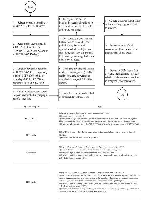
(11) The following figure provides an overview of testing under this section:
Figure 1 to Paragraph (a)(11) of §1036.545—Overview of Powertrain Testing.
(b) Test configuration. Select a powertrain for testing as described in §1036.235 or 40 CFR 1037.235 as applicable. Set up the engine according to 40 CFR 1065.110 and 1065.405(b). Set the engine's idle speed to idle speed defined in 40 CFR 1037.520(h)(1).
(1) The default test configuration consists of a powertrain with all components upstream of the axle. This involves connecting the powertrain's output shaft directly to the dynamometer or to a gear box with a fixed gear ratio and measuring torque at the axle input shaft. You may instead set up the dynamometer to connect at the wheel hubs and measure torque at that location. The preceding sentence may apply if your powertrain configuration requires it, such as for hybrid powertrains or if you want to represent the axle performance with powertrain test results. You may alternatively test the powertrain with a chassis dynamometer if you measure speed and torque at the powertrain's output shaft or wheel hubs.
(2) For testing hybrid engines, connect the engine's crankshaft directly to the dynamometer and measure torque at that location.
(c) Powertrain temperatures during testing. Cool the powertrain during testing so temperatures for oil, coolant, block, head, transmission, battery, and power electronics are within the manufacturer's expected ranges for normal operation. You may use electronic control module outputs to comply with this paragraph (c). You may use auxiliary coolers and fans.
(d) Engine break in. Break in the engine according to 40 CFR 1065.405(c), the axle assembly according to 40 CFR 1037.560, and the transmission according to 40 CFR 1037.565. You may instead break in the powertrain as a complete system using the engine break in procedure in 40 CFR 1065.405(c).
(e) Dynamometer setup. Set the dynamometer to operate in speed-control mode (or torque-control mode for hybrid engine testing at idle, including idle portions of transient duty cycles). Record data as described in 40 CFR 1065.202. Command and control the dynamometer speed at a minimum of 5 Hz, or 10 Hz for testing hybrid engines. Run the vehicle model to calculate the dynamometer setpoints at a rate of at least 100 Hz. If the dynamometer's command frequency is less than the vehicle model dynamometer setpoint frequency, subsample the calculated setpoints for commanding the dynamometer setpoints.
(f) Driveline and vehicle model. Use the GEM HIL model's driveline and vehicle submodels or the equations in this paragraph (f) to calculate the dynamometer speed setpoint, f nref,dyno, based on the torque measurement location. For all powertrains, configure GEM with the accessory load set to zero. For hybrid engines, configure GEM with the applicable accessory load as specified in §§1036.505, 1036.514, and 1036.525. For all powertrains and hybrid engines, configure GEM with the tire slip model disabled.
(1) Driveline model with a transmission in hardware. For testing with torque measurement at the axle input shaft or wheel hubs, calculate, f nref,dyno, using the GEM HIL model's driveline submodel or the following equation:

Eq. 1036.545-1
Where:
k a[speed] = drive axle ratio as determined in paragraph (h) of this section. Set k a[speed] equal to 1.0 if torque is measured at the wheel hubs.
v refi = simulated vehicle reference speed as calculated in paragraph (f)(3) of this section.
r [speed] = tire radius as determined in paragraph (h) of this section.
(2) Driveline model with a simulated transmission. For testing with the torque measurement at the engine's crankshaft, f nref,dyno is the dynamometer target speed from the GEM HIL model's transmission submodel. You may request our approval to change the transmission submodel, as long as the changes do not affect the gear selection logic. Before testing, initialize the transmission model with the engine's measured torque curve and the applicable steady-state fuel map from the GEM HIL model. You may request our approval to input your own steady-state fuel map. For example, this request for approval could include using a fuel map that represents the combined performance of the engine and hybrid components. Configure the torque converter to simulate neutral idle when using this procedure to generate engine fuel maps in §1036.505 or to perform the Supplemental Emission Test (SET) testing under §1036.510. You may change engine commanded torque at idle to better represent CITT for transient testing under §1036.512. You may change the simulated engine inertia to match the inertia of the engine under test. We will evaluate your requests under this paragraph (f)(2) based on your demonstration that the adjusted testing better represents in-use operation.
(i) The transmission submodel needs the following model inputs:
(A) Torque measured at the engine's crankshaft.
(B) Engine estimated torque determined from the electronic control module or by converting the instantaneous operator demand to an instantaneous torque in N·m.
(C) Dynamometer mode when idling (speed-control or torque-control).
(D) Measured engine speed when idling.
(E) Transmission output angular speed, f ni,transmission, calculated as follows:

Eq. 1036.545-2
Where:
k a[speed] = drive axle ratio as determined in paragraph (h) of this section.
v refi = simulated vehicle reference speed as calculated in paragraph (f)(3) of this section.
r [speed] = tire radius as determined in paragraph (h) of this section.
(ii) The transmission submodel generates the following model outputs:
(A) Dynamometer target speed.
(B) Dynamometer idle load.
(C) Transmission engine load limit.
(D) Engine speed target.
(3) Vehicle model. Calculate the simulated vehicle reference speed, ν refi, using the GEM HIL model's vehicle submodel or the equations in this paragraph (f)(3):

Eq. 1036.545-3
Where:
i = a time-based counter corresponding to each measurement during the sampling period.
Let v ref1 = 0; start calculations at i = 2. A 10-minute sampling period will generally involve 60,000 measurements.
T = instantaneous measured torque at the axle input, measured at the wheel hubs, or simulated by the GEM HIL model's transmission submodel. For configurations with multiple torque measurements, such as when measuring torque at the wheel hubs, T is the sum of all torque measurements.
Eff axle = axle efficiency. Use Eff axle = 0.955 for T ≥ 0, and use Eff axle = 1/0.955 for T < 0.
Use Eff axle = 1.0 if torque is measured at the wheel hubs.
M = vehicle mass for a vehicle class as determined in paragraph (h) of this section.
g = gravitational constant = 9.80665 m/s 2 .
C rr = coefficient of rolling resistance for a vehicle class as determined in paragraph (h) of this section.
G -1 = the percent grade interpolated at distance, D -1, from the duty cycle in 40 CFR part 1037, appendix D, corresponding to measurement (i -1).

Eq. 1036.545-4
ρ = air density at reference conditions. Use ρ = 1.1845 kg/m 3 .
C = drag area for a vehicle class as determined in paragraph (h) of this section.
F brake, -1 = instantaneous braking force applied by the driver model.
F grade , -1 = M · g · sin(atan(G -1 ))
Eq. 1036.545-5
Δt = the time interval between measurements. For example, at 100 Hz, Δt = 0.0100 seconds.
M rotating = inertial mass of rotating components. Let M rotating = 340 kg for vocational Light HDV or vocational Medium HDV. See paragraph (h) of this section for tractors and for vocational Heavy HDV.
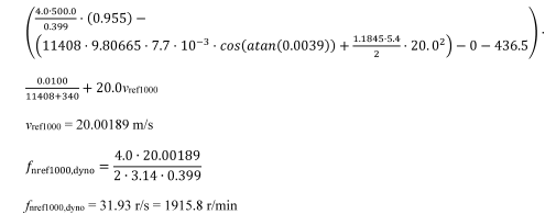
(4) Example. The following example illustrates a calculation of f nref,dyno using paragraph (f)(1) of this section where torque is measured at the axle input shaft. This example is for a vocational Light HDV or vocational Medium HDV with 6 speed automatic transmission at B speed (test 4 in table 1 to paragraph (h)(2)(ii) of this section).
k aB = 4.0
r B = 0.399 m
T 999 = 500.0 N·m
C rr = 7.7 N/kN = 7.7·10 −3 N/N
M = 11408 kg
C dA = 5.4 m 2
G 999 = 0.39% = 0.0039

F brake,999 = 0 N
v ref,999 = 20.0 m/s
F grade,999 = 11408 · 9.81 · sin(atan(0.0039)) = 436.5 N
Δ t = 0.0100 s
M rotating = 340 kg
v ref1000 =
(g) Driver model. Use the GEM HIL model's driver submodel or design a driver model to simulate a human driver modulating the throttle and brake pedals. In either case, tune the model to follow the test cycle as closely as possible meeting the following specifications:
(1) The driver model must meet the following speed requirements:
(i) For operation over the highway cruise cycles, the speed requirements described in 40 CFR 1066.425(b) and (c).
(ii) For operation over the Heavy-Duty Transient Test Cycle specified in 40 CFR part 1037, appendix A, the SET as defined §1036.510, the Federal Test Procedure (FTP) as defined in §1036.512, and the Low Load Cycle (LLC) as defined in §1036.514, the speed requirements described in 40 CFR 1066.425(b) and (c).
(iii) The exceptions in 40 CFR 1066.425(b)(4) apply to the highway cruise cycles, the Heavy-Duty Transient Test Cycle specified in 40 CFR part 1037, appendix A, SET, FTP, and LLC.
(iv) If the speeds do not conform to these criteria, the test is not valid and must be repeated.
(2) Send a brake signal when operator demand is zero and vehicle speed is greater than the reference vehicle speed from the test cycle. Include a delay before changing the brake signal to prevent dithering, consistent with good engineering judgment.
(3) Allow braking only if operator demand is zero.
(4) Compensate for the distance driven over the duty cycle over the course of the test. Use the following equation to perform the compensation in real time to determine your time in the cycle:

Eq. 1036.545-6
Where:
vehicle = measured vehicle speed.
cycle = reference speed from the test cycle. If cycle, i -1 < 1.0 m/s, set cycle, i -1 = vehicle, i -1.
(h) Vehicle configurations to evaluate for generating fuel maps as defined in §1036.505. Configure the driveline and vehicle models from paragraph (f) of this section in the test cell to test the powertrain. Simulate multiple vehicle configurations that represent the range of intended vehicle applications using one of the following options:
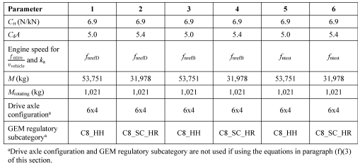
(1) For known vehicle configurations, use at least three equally spaced axle ratios or tire sizes and three different road loads (nine configurations), or at least four equally spaced axle ratios or tire sizes and two different road loads (eight configurations). Select axle ratios to represent the full range of expected vehicle installations. Select axle ratios and tire sizes such that the ratio of engine speed to vehicle speed covers the range of ratios of minimum and maximum engine speed to vehicle speed when the transmission is in top gear for the vehicles in which the powertrain will be installed. Note that you do not have to use the same axle ratios and tire sizes for each GEM regulatory subcategory. You may determine appropriate C rr, C d A, and mass values to cover the range of intended vehicle applications or you may use the C rr, C d A, and mass values specified in paragraph (h)(2) of this section.
(2) If vehicle configurations are not known, determine the vehicle model inputs for a set of vehicle configurations as described in §1036.540(c)(3) with the following exceptions:
(i) In the equations of §1036.540(c)(3)(i), k topgear is the actual top gear ratio of the powertrain instead of the transmission gear ratio in the highest available gear given in table 1 to paragraph (c)(2) of §1036.540.
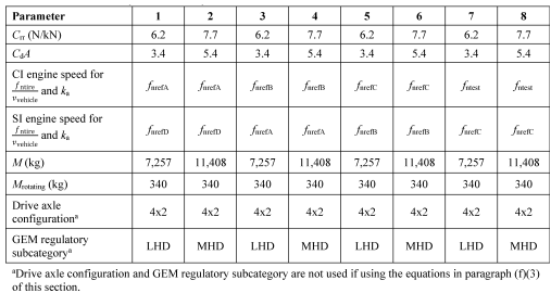
(ii) Test at least eight different vehicle configurations for powertrains that will be installed in Spark-ignition HDE, vocational Light HDV, and vocational Medium HDV using the following table instead of table 2 to paragraph (c)(3)(ii) of §1036.540:
TABLE 1 TO PARAGRAPH (h)(2)(ii) OF § 1036.545—VEHICLE CONFIGURATIONS FOR TESTING SPARK-IGNITION HDE, AND MEDIUM HDE
(iii) Select and test vehicle configurations as described in §1036.540(c)(3)(iii) for powertrains that will be installed in vocational Heavy HDV and tractors using the following tables instead of tables 3 and 4 to paragraph (c)(3)(iii) of §1036.540:
TABLE 2 TO PARAGRAPH (h)(2)(iii) OF § 1036.545—VEHICLE CONFIGURATIONS FOR TESTING GENERAL PURPOSE TRACTORS AND VOCATIONAL HEAVY HDV
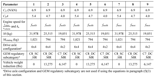
TABLE 3 TO PARAGRAPH (h)(2)(iii) of § 1036.545—VEHICLE CONFIGURATIONS FOR TESTING HEAVY HDE INSTALLED IN HEAVY-HAUL TRACTORS
(3) For hybrid powertrain systems where the transmission will be simulated, use the transmission parameters defined in §1036.540(c)(2) to determine transmission type and gear ratio. Use a fixed transmission efficiency of 0.95. The GEM HIL transmission model uses a transmission parameter file for each test that includes the transmission type, gear ratios, lockup gear, torque limit per gear from §1036.540(c)(2) and the values from §1036.505(b)(4) and (c).
(i) [Reserved]
(j) Duty cycles to evaluate. Operate the powertrain over each of the duty cycles specified in 40 CFR 1037.510(a)(2), and for each applicable vehicle configuration from paragraph (h) of this section. Determine cycle-average powertrain fuel maps by testing the powertrain using the procedures in §1036.540(d) with the following exceptions:
(1) Understand “engine” to mean “powertrain”.
(2) Warm up the powertrain as described in §1036.520(d).
(3) Within 90 seconds after concluding the warm-up, start the transition to the preconditioning cycle as described in paragraph (j)(5) of this section.
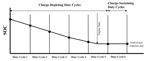
(4) For plug-in hybrid engines, precondition the battery and then complete all back-to-back tests for each vehicle configuration according to 40 CFR 1066.501(a)(3) before moving to the next vehicle configuration. The following figure illustrates a charge-depleting test sequence with engine operation during two duty cycles, which are used for criteria pollutant determination:
Figure 2 to Paragraph (j)(4) of §1036.545—Generic Charge-Depleting Test Sequence
(5) If the preceding duty cycle does not end at 0 mi/hr, transition between duty cycles by decelerating at a rate of 2 mi/hr/s at 0% grade until the vehicle reaches zero speed. Shut off the powertrain. Prepare the powertrain and test cell for the next duty-cycle.
(6) Start the next duty-cycle within 60 to 180 seconds after shutting off the powertrain.
(i) To start the next duty-cycle, for hybrid powertrains, key on the vehicle and then start the duty-cycle. For conventional powertrains key on the vehicle, start the engine, wait for the engine to stabilize at idle speed, and then start the duty-cycle.
(ii) If the duty-cycle does not start at 0 mi/hr, transition to the next duty cycle by accelerating at a target rate of 1 mi/hr/s at 0% grade. Stabilize for 10 seconds at the initial duty cycle conditions and start the duty-cycle.
(7) Calculate cycle work using GEM or the speed and torque from the driveline and vehicle models from paragraph (f) of this section to determine the sequence of duty cycles.
(8) Calculate the mass of fuel consumed for idle duty cycles as described in paragraph (n) of this section.
(k) Measuring NOX emissions. Measure NO X emissions for each sampling period in grams. You may perform these measurements using a NO X emission-measurement system that meets the requirements of 40 CFR part 1065, subpart J. If a system malfunction prevents you from measuring NO X emissions during a test under this section but the test otherwise gives valid results, you may consider this a valid test and omit the NO X emission measurements; however, we may require you to repeat the test if we determine that you inappropriately voided the test with respect to NO X emission measurement.
(l) [Reserved]
(m) Measured output speed validation. For each test point, validate the measured output speed with the corresponding reference values. If speed is measured at more than one location, the measurements at each location must meet validation requirements. If the range of reference speed is less than 10 percent of the mean reference speed, you need to meet only the standard error of the estimate in table 4 to this paragraph (m). You may delete points when the vehicle is stopped. If your speed measurement is not at the location of ƒ nref, correct your measured speed using the constant speed ratio between the two locations. Apply cycle-validation criteria for each separate transient or highway cruise cycle based on the following parameters:
| Parameter a | Speed control |
|---|---|
| Slope, a 1 | 0.990 ≤ a 1 ≤ 1.010. |
| Absolute value of intercept, | a 0 | | ≤2.0% of maximum ƒ nref speed. |
| Standard error of the estimate, SEE | ≤2.0% of maximum ƒ nref speed. |
| Coefficient of determination, r 2 | ≥0.990. |
| a Determine values for specified parameters as described in 40 CFR 1065.514(e) by comparing measured and reference values for ƒ nref,dyno. | |
(n) Fuel consumption at idle. Record measurements using direct and/or indirect measurement of fuel flow. Determine the fuel-consumption rates at idle for the applicable duty cycles described in 40 CFR 1037.510(a)(2) as follows:
(1) Direct fuel flow measurement. Determine the corresponding mean values for mean idle fuel mass flow rate, m fuelidle, for each duty cycle, as applicable. Use of redundant direct fuel-flow measurements require our advance approval.
(2) Indirect fuel flow measurement. Record speed and torque and measure emissions and other inputs needed to run the chemical balance in 40 CFR 1065.655(c). Determine the corresponding mean values for each duty cycle. Use of redundant indirect fuel-flow measurements require our advance approval. Measure background concentration as described in §1036.535(b)(4)(ii). We recommend setting the CVS flow rate as low as possible to minimize background, but without introducing errors related to insufficient mixing or other operational considerations. Note that for this testing 40 CFR 1065.140(e) does not apply, including the minimum dilution ratio of 2:1 in the primary dilution stage. Calculate the idle fuel mass flow rate for each duty cycle, m fuelidle, for each set of vehicle settings, as follows:

Eq. 1036.545-7
Where:
M C = molar mass of carbon.
w Cmeas = carbon mass fraction of fuel (or mixture of test fuels) as determined in 40 CFR 1065.655(d), except that you may not use the default properties in 40 CFR 1065.655(e)(5) to determine α, β, and w C for liquid fuels.
n exh = the mean raw exhaust molar flow rate from which you measured emissions according to 40 CFR 1065.655.
χ Ccombdry = the mean concentration of carbon from fuel and any injected fluids in the exhaust per mole of dry exhaust.
χ H2Oexhdry = the mean concentration of H 2 O in exhaust per mole of dry exhaust.
m CO2DEF = the mean CO 2 mass emission rate resulting from diesel exhaust fluid decomposition over the duty cycle as determined in §1036.535(b)(9). If your engine does not use diesel exhaust fluid, or if you choose not to perform this correction, set equal to 0.
M CO2 = molar mass of carbon dioxide.
Example:
M C = 12.0107 g/mol
w Cmeas = 0.867
n exh = 25.534 mol/s
χ Ccombdry = 2.805·10 −3 mol/mol
χ H2Oexhdry = 3.53·10 −2 mol/mol
m CO2DEF = 0.0726 g/s
M CO2 = 44.0095

(o) Create GEM inputs. Use the results of powertrain testing to determine GEM inputs for the different simulated vehicle configurations as follows:
(1) Correct the measured or calculated fuel masses, m fuel[cycle], and mean idle fuel mass flow rates, m fuelidle, if applicable, for each test result to a mass-specific net energy content of a reference fuel as described in §1036.535(e), replacing m fuel with m fuel[cycle] where applicable in Eq. 1036.535-4.
(2) Declare fuel masses, m fuel[cycle] and m fuelidle . Determine m fuel[cycle] using the calculated fuel mass consumption values described in §1036.540(d)(12). In addition, declare mean fuel mass flow rate for each applicable idle duty cycle, m fuelidle . These declared values may not be lower than any corresponding measured values determined in this section. If you use both direct and indirect measurement of fuel flow, determine the corresponding declared values as described in §1036.535(g)(2) and (3). These declared values, which serve as emission standards, collectively represent the powertrain fuel map for certification.
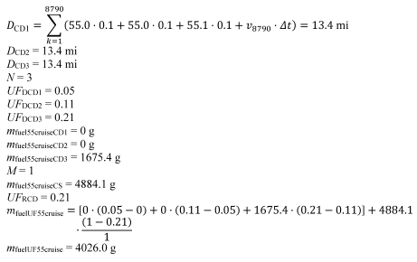
(3) For engines designed for plug-in hybrid electric vehicles, the mass of fuel for each cycle, m fuel[cycle], is the utility factor-weighted fuel mass, m fuelUF[cycle]. This is determined by calculating m fuel for the full charge-depleting and charge-sustaining portions of the test and weighting the results, using the following equation:

Eq. 1036.545-8
Where:
i = an indexing variable that represents one test interval.
N = total number of charge-depleting test intervals.
m fuel[cycle]CD = total mass of fuel in the charge-depleting portion of the test for each test interval, i , starting from i = 1, including the test interval(s) from the transition phase.
UF DCD = utility factor fraction at distance D CD from Eq. 1036.510-11 as determined by interpolating the approved utility factor curve for each test interval, i, starting from i = 1. Let UF DCD0 = 0
j = an indexing variable that represents one test interval.
M = total number of charge-sustaining test intervals.
m fuel[cycle]CS = total mass of fuel over the charge-sustaining portion of the test for each test interval, j , starting from j = 1.
UF RCD = utility factor fraction at the full charge-depleting distance, R CD, as determined by interpolating the approved utility factor curve. R CD is the cumulative distance driven over N charge-depleting test intervals.

Eq. 1036.545-9
Where:
k = an indexing variable that represents one recorded velocity value.
Q = total number of measurements over the test interval.
v = vehicle velocity at each time step, k , starting from k = 1. For tests completed under this section, v is the vehicle velocity as determined by Eq. 1036.545-1. Note that this should include charge- depleting test intervals that start when the engine is not yet operating.
Δ t = 1/ƒ record
ƒ record = the record rate.
Example for the 55 mi/hr cruise cycle:
Q = 8790
1 = 55.0 mi/hr
2 = 55.0 mi/hr
3 = 55.1 mi/hr
ƒ record = 10 Hz
Δ t = 1/10 Hz = 0.1 s
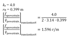
(4) For the transient cycle specified in 40 CFR 1037.510(a)(2)(i), calculate powertrain output speed per unit of vehicle speed using one of the following methods:
(i) For testing with torque measurement at the axle input shaft:

Eq. 1036.545-10
Example:
(ii) For testing with torque measurement at the wheel hubs, use Eq. 1036.545-8 setting k a equal to 1.
(iii) For testing with torque measurement at the engine's crankshaft:

Eq. 1036.545-11
Where:
f nengine = average engine speed when vehicle speed is at or above 0.100 m/s.
v ref = average simulated vehicle speed at or above 0.100 m/s.
Example:
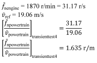
(5) Calculate engine idle speed, by taking the average engine speed measured during the transient cycle test while the vehicle speed is below 0.100 m/s. (Note: Use all the charge-sustaining test intervals when determining engine idle speed for plug-in hybrid powertrains.)ƒ
(6) For the cruise cycles specified in 40 CFR 1037.510(a)(2)(ii), calculate the average powertrain output speed, ƒ npowertrain, and the average powertrain output torque (positive torque only), T powertrain, at vehicle speed at or above 0.100 m/s. (Note: Use all the charge-sustaining and charge-depleting test intervals when determining ƒ npowertrain and T powertrain for plug-in hybrid powertrains.)
(7) Calculate positive work, W [cycle], as the work over the duty cycle at the axle input shaft, wheel hubs, or the engine's crankshaft, as applicable, when vehicle speed is at or above 0.100 m/s. For plug-in hybrid powertrains, calculate W [cycle] by calculating the positive work over each of the charge-sustaining and charge-depleting test intervals and then averaging them together. If speed and torque are measured at more than one location, determine W [cycle] by integrating the sum of the power calculated from measured speed and torque measurements at each location.
(8) The following tables illustrate the GEM data inputs corresponding to the different vehicle configurations for a given duty cycle:
(i) For the transient cycle:
Table 5 to Paragraph (o)(8)(i) of §1036.545—Example of Output Matrix for Transient Cycle Vehicle Configurations

(ii) For the cruise cycles:
Table 6 to Paragraph ((o)(8)(ii) of §1036.545—Generic Example of Output Matrix for Cruise Cycle Vehicle Configurations

(p) Determine usable battery energy. Determine usable battery energy (UBE) for plug-in hybrid powertrains using one of the following procedures:
(1) Select a representative vehicle configuration from paragraph (h) of this section. Measure DC discharge energy, E DCD, in DC watt-hours and measure DC discharge current per hour, C D, for the charge-depleting test intervals of the Heavy-Duty Transient Test Cycle in 40 CFR part 1037, appendix A. The measurement period must include all the current flowing into and out of the battery pack during the charge-depleting test intervals, including current associated with regenerative braking. Eq. 1036.545-12 shows how to calculate E DCD, but the power analyzer specified in paragraph (a)(10)(i) of this section will typically perform this calculation internally. Battery voltage measurements made by the powertrain's on-board sensors (such as those available with a diagnostic port) may be used for calculating E DCD if they are equivalent to those from the power analyzer.

Eq. 1036.545-12
Where:
i = an indexing variable that represents one individual measurement.
N = total number of measurements.
V = battery DC bus voltage.
I = battery current.
Δ t = 1/ƒ record
ƒ record = the data recording frequency.
Example:
N = 13360
V 1 = 454.0
V 2 = 454. 0
I 1 = 0
I 2 = 0
ƒ record = 20 Hz
Δ t = 1/20 = 0.05 s

(2) Determine a declared UBE that is at or below the corresponding value determined in paragraph (p)(1) of this section, including those from redundant measurements. This declared UBE serves as UBE certified determined under 40 CFR 1037.115(f).
[89 FR 29752, Apr. 22, 2024]
