['CMV Parts and Maintenance']
['Vehicle maintenance']
10/30/2024
...
S1. Scope and Purpose. This standard specifies requirements for vehicle door locks and door retention components, including latches, hinges, and other supporting means, to minimize the likelihood of occupants being ejected from a vehicle as a result of impact.
S2. Application. This standard applies to passenger cars, multipurpose passenger vehicles, trucks designed to carry at least one person, and buses with a gross vehicle weight rating (GVWR) of 4,536 kg or less.
S3. Definitions.
Auxiliary Door Latch is a latch equipped with a fully latched position, with or without a secondary latched position, and fitted to a door or door system equipped with a primary door latch system.
Auxiliary Door Latch System consists of door latches and strikers other than those associated with the primary door latch system.
Back Door is a door or door system on the back end of a motor vehicle through which passengers can enter or depart the vehicle or cargo can be loaded or unloaded. It does not include:
(a) A trunk lid; or
(b) A door or window composed entirely of glazing material and whose latches and/or hinge systems are attached directly to the glazing material.
Body Member is that portion of the hinge normally affixed to the body structure.
Door Closure Warning System is a system that will activate a visual signal when a door latch system is not in its fully latched position and the vehicle ignition is activated.
Door Hinge System is one or more hinges used to support a door.
Door Latch System consists of latches and strikers installed on a door system.
Door Member is that portion of the hinge normally affixed to the door structure and constituting the swinging member.
Door System
is the door, latch, striker, hinges, sliding track combinations and other door retention components on a door and its surrounding doorframe. The door system of a double door includes both doors.
Double Door is a system of two doors where the front door or wing door opens first and connects to the rear door or bolted door, which opens second.
Folding Door is a movable barrier, which will close off an entranceway to a bus, multipurpose passenger vehicle or truck, consisting of two or more hinge panels that swing, slide, or rotate; does not have a striker and latch assembly.
Fork-bolt is the part of the latch that engages and retains the striker when in a latched position.
Fork-bolt Opening Direction is the direction opposite to that in which the striker enters the latch to engage the fork-bolt.
Fully Latched Position is the coupling condition of the latch that retains the door in a completely closed position.
Hinge is a device system used to position the door relative to the body structure and control the path of the door swing for passenger ingress and egress.
Hinge Pin is that portion of the hinge normally interconnecting the body and door members and establishing the swing axis.
Latch is a device employed to maintain the door in a closed position relative to the vehicle body with provisions for deliberate release (or operation).
Primary Door Latch is a latch equipped with both a fully latched position and a secondary latched position and is designated as a “primary door latch” by the manufacturer.
Primary Door Latch System consists of a primary door latch(s) and a striker(s).
Secondary Latched Position refers to the coupling condition of the latch that retains the door in a partially closed position.
Side Front Door is a door that, in a side view, has 50 percent or more of its opening area forward of the rearmost point on the driver's seat back, when the seat back is adjusted to its most vertical and rearward position. For vehicles without a driver's designated seating position it is a door that in a side view, has 50 percent or more of its opening area forward of the rearmost point on the most rearward passenger's seat back in the front row of seats, when the seat backs are adjusted to their most vertical and rearward position.
Side Rear Door is a door that, in a side view, has 50 percent or more of its opening area to the rear of the rearmost point on the driver's seat back, when the driver's seat is adjusted to its most vertical and rearward position. For vehicles without a driver's designated seating position it is a door that in a side view, has 50 percent or more of its opening area rear of the rearmost point on the most rearward passenger's seat back in the front row of seats, when the seat backs are adjusted to their most vertical and rearward position.
Striker is a device with which the latch engages to maintain the door in the fully latched or secondary latched position.
Trunk Lid is a movable body panel that provides access from outside the vehicle to a space wholly partitioned from the occupant compartment by a permanently attached partition or fixed or fold-down seat back.
S4. Requirments. The requirements apply to all side and back doors, that lead directly into a compartment that contains one or more seating accommodations and the associated door components, except for those on folding doors, roll-up doors, detachable doors, bus doors used only for emergency egress purposes and labeled accordingly and on bus doors to accommodate a permanently attached wheelchair lift system that when the device is in the retracted position, the lift platform retracts to a vertical orientation parallel to and in close proximity with the interior surface of the lift door and in that position, the platform completely covers the doorway opening, has fixed attachments to the vehicle and provides a barricade to the doorway. The bus wheelchair lift door must be linked to an alarm system consisting of either a flashing visible signal located in the driver’s compartment or an alarm audible to the driver that is activated when the door is not fully closed and the vehicle ignition is activated.
S4.1 Hinged Doors
S4.1.1 Primary and Auxiliary Door Latch Systems. Each hinged door system shall be equipped with at least one primary door latch system. By the time a vehicle is certified a manufacturer shall designate the door latch system(s) that is the “primary door latch system(s).” Upon certification, a manufacturer may not thereafter alter the designation of a primary door latch system. Each manufacturer shall, upon request from the National Highway Traffic Safety Administration, provide information regarding such designation.
S4.1.1.1 Load Test One.
(a) Each primary door latch system and auxiliary door latch system, when in the fully latched position, shall not separate when a load of 11,000 N is applied in the direction perpendicular to the face of the latch such that the latch and the striker anchorage are not compressed against each other, when tested in accordance with S5.1.1.1.
(b) When in the secondary latched position, the primary door latch system shall not separate when a load of 4,500 N is applied in the same direction specified in paragraph (a) of this section when tested in accordance with S5.1.1.1.
S4.1.1.2 Load Test Two.
(a) Each primary door latch system and auxiliary door latch system, when in the fully latched position, shall not separate when a load of 9,000 N is applied in the fork-bolt opening direction and parallel to the face of the latch, when tested in accordance with S5.1.1.2.
(b) When in the secondary latched position, the primary door latch system shall not separate when a load of 4,500 N is applied in the same direction specified in paragraph (a) of this section when tested in accordance with S5.1.1.2.
S4.1.1.3 Load Test Three. (Applicable only to back doors that open in a vertical direction). Each primary door latch system on back doors, when in the fully latched position, shall not separate when a load of 9,000 N is applied in a direction orthogonal to the directions specified in S4.1.1.1 and S4.1.1.2 when tested in accordance with S5.1.1.3.
S4.1.1.4 Inertial Load. Each primary door latch system and auxiliary door latch system shall meet either the dynamic requirements specified in paragraphs (a) and (b) of S4.1.1.4 or the calculation of inertial load resistance specified in paragraph (c) of S4.1.1.4.
(a) Each primary door latch and auxiliary door latch on each hinged door shall not disengage from the fully latched position when an inertia load is applied to the door latch system, including the latch and its activation device, in the directions parallel to the vehicle's longitudinal and transverse axes with the locking device disengaged, when tested as specified in S5.1.1.4(b).
(b) Each primary door latch and auxiliary door latch on each hinged back door shall also not disengage from the fully latched position when an inertia load is applied to the door latch system, including the latch and its activation device, in the direction parallel to the vehicle's vertical axis with the locking device disengaged, when tested as specified in S5.1.1.4(b).
(c) Each component or subassembly is calculated for its minimum inertial load resistance in a particular direction. The combined resistance to the unlatching operation must assure that the door latch system, when properly assembled in the vehicle door, will remain latched when subjected to an inertial load of 30 g in the vehicle directions specified in paragraph (a) of this section or paragraph (b) of this section, as applicable, when calculated in accordance with S5.1.1.4 (a).
S4.1.2 Door Hinges.
S4.1.2.1 When tested in accordance with S5.1.2, each door hinge system shall:
(a) Support the door,
(b) Not separate when a longitudinal load of 11,000 N is applied,
(c) Not separate when a transverse load of 9,000 N is applied, and
(d) For back doors,
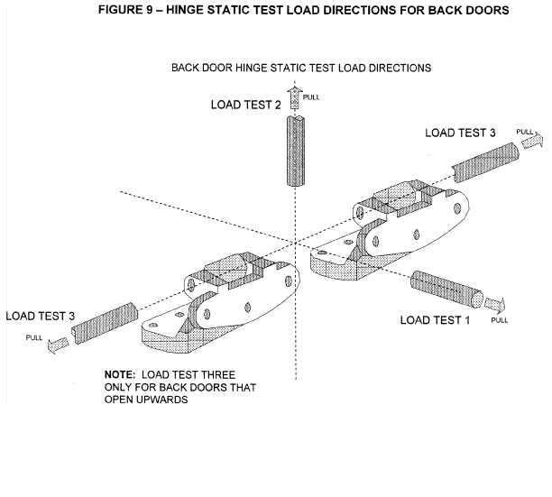
(1) Not separate when a load of 11,000 N is applied perpendicular to the hinge face plate (longitudinal load test) such that the hinge plates are not compressed against each other (Load Test One).
(2) Not separate when a load of 9,000 N is applied perpendicular to the axis of the hinge pin and parallel to the hinge face plate (transverse load test) such that the hinge plates are not compressed against each other (Load Test Two).
(3) Not separate when a load of 9,000 N is applied in the direction of the axis of the hinge pin (Load Test Three—only for back doors that open in a vertical direction).
S4.1.2.2 If a single hinge within the hinge system is tested instead of the entire hinge system, the hinge must bear a load proportional to the total number of hinges in the hinge system. (For example, an individual hinge in a two-hinge system must be capable of withstanding 50% of the load requirements of the total system.)
S4.1.2.3 On side doors with rear mounted hinges that can be operated independently of other doors,
(a) The interior door handle shall be inoperative when the speed of the vehicle is greater than or equal to 4 km/h, and
(b) A door closure warning system shall be provided for those doors. The door closure warning system shall be located where it can be clearly seen by the driver.
S4.2 Sliding Side Doors.
S4.2.1 Latch System. Each sliding door system shall be equipped with either:
(a) At least one primary door latch system, or
(b) A door latch system with a fully latched position and a door closure warning system. The door closure warning system shall be located where it can be clearly seen by the driver. Upon certification a manufacturer may not thereafter alter the designation of a primary latch. Each manufacturer shall, upon request from the National Highway Traffic Safety Administration, provide information regarding such designation.
S4.2.1.1 Load Test One.
(a) At least one door latch system, when in the fully latched position, shall not separate when a load of 11,000 N is applied in the direction perpendicular to the face of the latch such that the latch and the striker anchorage are not compressed against each other, when tested in accordance with S5.2.1.1.
(b) In the case of a primary door latch system, when in the secondary latched position, the door latch system shall not separate when a load of 4,500 N is applied in the same direction specified in paragraph (a) of this section when tested in accordance with S5.2.1.1.
S4.2.1.2 Load Test Two.
(a) At least one door latch system, when in the fully latched position, shall not separate when a load of 9,000 N is applied in the fork-bolt opening direction and parallel to the face of the latch when tested in accordance with S5.2.1.2.
(b) In the case of a primary door latch system, when in the secondary latched position, the door latch system shall not separate when a load of 4,500 N is applied in the same direction specified in paragraph (a) of this section when tested in accordance with S5.2.1.2.
S4.2.1.3 Inertial Load. Each door latch system certified as meeting the requirements of S4.2.1.1 and S4.2.1.2 shall meet either the dynamic requirements specified in paragraph (a) of this section or the calculation of inertial load resistance specified in paragraph (b) of this section.
(a) The door latch system shall not disengage from the fully latched position when an inertial load is applied to the door latch system, including the latch and its activation mechanism, in the directions parallel to the vehicle's longitudinal and transversal axes with the locking mechanism disengaged, and when tested in accordance with S5.1.1.4(b).
(b) The minimum inertial load resistance can be calculated for each component or subassembly. Their combined resistance to the unlatching operation must assure that the door latch system, when properly assembled in the vehicle door, will remain latched when subjected to an inertia load of 30 g in the vehicle directions specified in paragraph (a) of this section, when calculated in accordance with S5.1.1.4(a).
S4.2.2 Door System.
S4.2.2.1 The track and slide combination or other supporting means for each sliding door, while in the closed fully latched position, shall not separate from the door frame when a total force of 18,000 N along the vehicle transverse axis is applied to the door as specified in S5.2.2.
S4.2.2.2 When a sliding door system is tested in accordance with S5.2.2, the following conditions shall not occur:
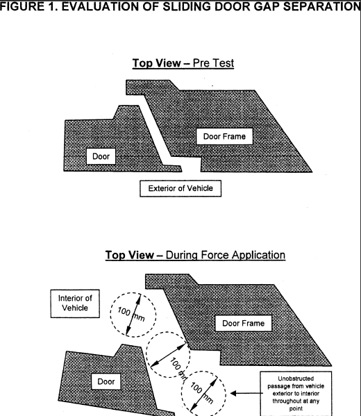
(a) A separation which permits a sphere with a diameter of 100 mm to pass unobstructed between the exterior of the vehicle to the interior of the vehicle, while the required force is maintained as shown in Figure 1.
(b) Either force application device reaches a total displacement of 300 mm.
S4.2.2.3 This S4.2.2 applies to vehicles manufactured on or after September 1, 2010.
S4.3 Door Locks. Each door shall be equipped with at least one locking device which, when engaged, shall prevent operation of the exterior door handle or other exterior latch release control and which has an operating means and a lock release/engagement device located within the interior of the vehicle.
S4.3.1 Rear side doors. Each rear side door shall be equipped with at least one locking device which has a lock release/engagement mechanism located within the interior of the vehicle and readily accessible to the driver of the vehicle or an occupant seated adjacent to the door, and which, when engaged, prevents operation of the interior door handle or other interior latch release control and requires separate actions to unlock the door and operate the interior door handle or other interior latch release control.
S4.3.2 Back doors. Each back door equipped with an interior door handle or other interior latch release control, shall be equipped with at least one locking device that meets the requirements of S4.3.1.
S5 Test Procedures.
S5.1 Hinged Doors.
S5.1.1 Primary and Auxiliary Door Latches.
S5.1.1.1 Load Test One Force Application. The test procedures for S4.1.1.1 and S4.2.1.1 are as follows:
(a) Fully latched position.
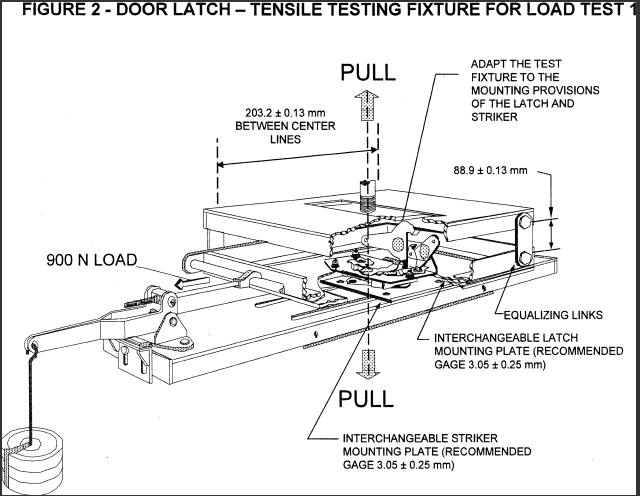
(1) Attach the test fixture shown in Figure 2 to the mounting provisions of the latch and striker. Align the direction of engagement parallel to the linkage of the fixture. Mount the fixture with latch and striker in the fully latched position in the test machine so as to apply a load perpendicular to the face of the latch.
(2) Locate weights so as to apply a 900 N load tending to separate the latch and striker in the direction of the latch opening.
(b) Secondary Latched Position.
(1) Attach the test fixture shown in Figure 2 to the mounting provisions of the latch and striker. Align the direction of engagement parallel to the linkage of the fixture. Mount the fixture with latch and striker in the secondary position in the test machine so as to apply a load perpendicular to the face of the latch.
(2) Locate weights so as to apply a 900 N load tending to separate the latch and striker in the direction of the latch opening.
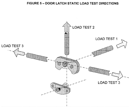
(3) Apply the test load, in the direction specified in S4.1.1.1 and Figure 5, at a rate not to exceed 5 mm/min until the required load has been achieved. Record maximum load achieved.
(4) The test plate to which the door latch is mounted will have a striker cut-out configuration similar to the environment in which the door latch will be mounted on normal vehicle doors.
S5.1.1.2 Load Test Two Force Application. The test procedures for S4.1.1.2 and S4.2.1.2 are as follows:
(a) Fully Latched Position.
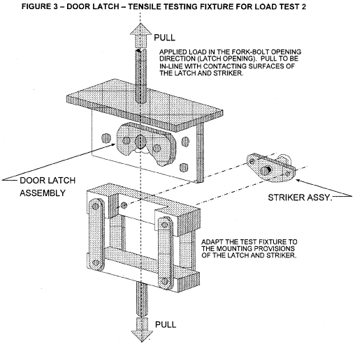
(1) Adapt the test fixture shown in Figure 3 to the mounting provisions of the latch and striker. Mount the fixture with latch and striker in the fully latched position in the test machine so to apply a load in the direction of latch opening.
(2) Apply the test load, in the direction specified in S4.1.1.2 and Figure 5, at a rate not to exceed 5 mm/min until the required load has been achieved. Record the maximum load achieved.
(b) Secondary Latched Position.
(1) Adapt the test fixture shown in Figure 3 to the mounting provisions of the latch and striker. Mount the fixture with latch and striker in the secondary latched position in the test machine so as to apply a load in the direction of latch opening.
(2) Apply the test load, in the direction specified in S4.1.1.2 and Figure 5, at a rate not to exceed 5 mm/min until the required load has been achieved. Record the maximum load achieved.
S5.1.1.3 Load Test Three Force Application. The test procedures for S4.1.1.3 are as follows:
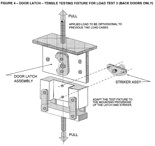
(a) Adapt the test fixture shown in Figure 4 to the mounting provisions of the latch and striker. Mount the fixture with latch and striker in the fully latched position in the test machine so as to apply a load in the direction specified in S4.1.1.3 and Figure 5.
(b) Apply the test load, in the direction specified in S4.1.1.3 and Figure 5, at a rate not to exceed 5 mm/min until the required load has been achieved. Record the maximum load required.
S5.1.1.4 Inertial Force Application. The test procedures for S4.1.1.4 and S4.2.1.3 are as follows:
(a) Calculation. The calculation is performed in accordance with paragraph 6 of SAE Recommended Practice J839 (1991) (incorporated by reference, see §571.5).
(b) Dynamic Test. The dynamic inertial force application is tested according to the setup specified in paragraph (1) or (2) of this section.
(1) Test Setup and Directions for Full Vehicle Test.
(i) Test Setup.
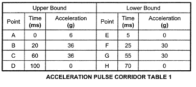
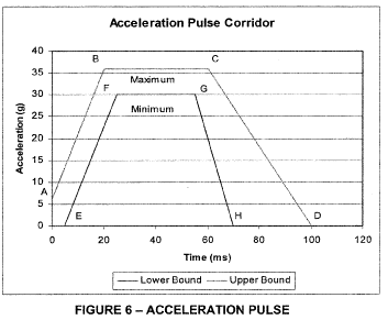
(A) Rigidly secure the full vehicle to an acceleration device that, when accelerated together, will assure that all points on the crash pulse curve are within the corridor defined in Table 1 and Figure 6.
(B) Install the equipment used to record door opening (doors may be tethered to avoid damaging the recording equipment).
(C) Close the door(s) to be tested and ensure that the door latch(es) is in the fully-latched position, that the door(s) is unlocked, and that all windows, if provided, on the door(s) are closed.
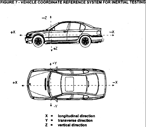
(ii) Test Directions. (See Figure 7)
(A) Longitudinal Setup 1. Orient the vehicle so that its longitudinal axis is aligned with the axis of the acceleration device, simulating a frontal impact.
(B) Longitudinal Setup 2. Orient the vehicle so that its longitudinal axis is aligned with the axis of the acceleration device, simulating a rear impact.
[Editor’s Note: The following paragraph is revised effective September 26, 2022. Revised text follows current paragraph.] [Change Notice]
(C) Transverse Setup 1. Orient the vehicle so that its transverse axis is aligned with the axis of the acceleration device, simulating a driver-side impact.
[Editor’s Note: Effective September 26, 2022, the previous paragraph is as follows.]
(C) Transverse Setup 1. Orient the vehicle so that its transverse axis is aligned with the axis of the acceleration device, simulating a left-side impact.
(D) Transverse Setup 2. (Only for vehicles having different door arrangements on each side.) Orient the vehicle so that its transverse axis is aligned with the axis of the acceleration device, simulating a side impact in the direction opposite to that described in b(1)(ii)(C) of this paragraph.
(2) Test Setup and Directions for Door Test.
(i) Test Setup.
(A) Mount the door assemblies, consisting of at least the door latch(es), exterior door handle(s) with mechanical latch operation, interior door opening lever(s), and locking device(s), either separately or combined to a test fixture. Each door and striker is mounted to the test fixture to correspond to its orientation on the vehicle and to the directions specified in b(1)(ii) of this paragraph.
(B) Mount the test fixture to the acceleration device, and install the equipment used to record door opening.
(C) Ensure that the door latch is in the fully-latched position, that the door is unlocked (doors may be tethered to avoid damaging the recording equipment), and that any windows, if provided, are closed.
(ii) Test Directions. (See Figure 7)
(A) Longitudinal Setup 1. Orient the door subsystem(s) on the acceleration device in the direction of a frontal impact.
(B) Longitudinal Setup 2. Orient the door subsystem(s) on the acceleration device in the direction of a rear impact.
(C) Transverse Setup 1. Orient the door subsystem(s) on the acceleration device in the direction of a driver-side impact.
(D) Transverse Setup 2. Orient the door subsystem(s) on the acceleration device in the direction opposite to that described in (b)(2)(ii)(C) of this paragraph.
(E) Vertical Setup 1 (applicable only to back doors that open in a vertical direction). Orient the door subsystem(s) on the acceleration device so that its vertical axis (when mounted in the vehicle) is aligned with the axis of the acceleration device, simulating a rollover impact where the force is applied in the direction from the top to the bottom of the door (when mounted in a vehicle).
(F) Vertical Setup 2 (applicable only to back doors that open in a vertical direction). Orient the door subsystem(s) on the acceleration device so that its vertical axis (when mounted in the vehicle) is aligned with the axis of the acceleration device, simulating a rollover impact where the force is applied in the direction opposite to that described in (b)(2)(ii)(E) of this paragraph.
(3) Test Operation.
(i) The acceleration device platform shall be instrumented with an accelerometer and data processing system that conforms to the requirements specified in SAE Recommended Practice J211-1 DEC2003 (incorporated by reference, see §571.5 ) Channel Class 60. The accelerometer sensitive axis is parallel to the direction of test platform travel.
(ii) Maintaining a minimum acceleration level of 30 g for a period of at least 30 ms, while keeping the recorded acceleration within the pulse corridor defined in Table 1 and Figure 6, accelerate the acceleration device in the following directions:
(A) For Full Vehicle Tests, in the directions specified in S5.1.1.4(b)(1)(ii)(A) through S5.1.1.4(b)(1)(ii)(D).
(B) For Door Tests, in the directions specified in S5.1.1.4(b)(2)(ii)(A) through S5.1.1.4(b)(2)(ii)(F).
(iii) Check recording device for door opening and/or closure during the test.
(iv) If at any point in time, the pulse exceeds 36 g and the test specifications are met, the test shall be considered valid.
S5.1.2 Door Hinges. The test procedures for S4.1.2 are as follows:
S5.1.2.1 Multiple Hinge Evaluation;
S5.1.2.1.1 Longitudinal Load Test.
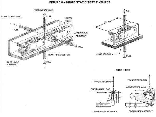
(a) Attach the test fixture illustrated in Figure 8 to the mounting provisions of the hinge system. Hinge attitude is configured to simulate vehicle position (door fully closed) relative to the hinge centerline. For test purposes, the distance between the extreme end of one hinge in the system to the extreme end of another hinge in the system is to be set at 406 mm ±4 mm. The load is to be applied equidistant between the linear center of the engaged portions of the hinge pins and through the centerline of the hinge pin in the longitudinal vehicle direction (see Figure 8).
(b) Apply the test load at a rate not to exceed 5 mm/min until the required load has been achieved. Record maximum load achieved.
S5.1.2.1.2 Transverse Load Test
(a) Attach the test fixture shown in Figure 8 to the mounting provisions of the hinge system. Hinge attitude is configured to simulate vehicle position (door fully closed) relative to the hinge centerline. For test purposes, the distance between the extreme end of one hinge in the system to the extreme opposite end of another hinge in the system is to be set at 406 mm ±4 mm. The load is to be applied equidistant between the linear center of the engaged portions of the hinge pins and through the centerline of the hinge pin in the transverse vehicle direction (see Figure 8).
(b) Apply the test load at a rate not to exceed 5 mm/min until the required load has been achieved. Record maximum load achieved.
S5.1.2.2 Back Door Hinge Load Test
(a) Load Test One
(1) Attach the test fixture illustrated in Figure 8 to the mounting provisions of the hinge system. Hinge attitude is configured to simulate vehicle position (door fully closed) relative to the hinge centerline. For test purposes, the distance between the extreme end of one hinge system in the system to the extreme opposite end of another hinge system is to be set at 406 ±4 mm. The load is to be applied equidistant between the linear center of the engaged portions of the hinge pins and through the centerline of the hinge pin, and as specified in S4.1.2.1(d)(1). (See Figure 9).
(2) Apply the test load at a rate not to exceed 5 mm/min until the required load has been achieved. Failure consists of a separation of either hinge. Record the maximum load achieved.
(b) Load Test Two
(1) Attach the test fixture illustrated in Figure 8 to the mounting provisions of the hinge system. Hinge attitude is configured to simulate vehicle position (door fully closed) relative to the hinge centerline. For test purposes, the distance between the extreme end of one hinge system in the system to the extreme opposite end of another hinge system is to be set at 406 ±4 mm. The load is to be applied equidistant between the linear center of the engaged portions of the hinge pins and through the centerline of the hinge pin, and as specified in S4.1.2.1(d)(2). (See Figure 9).
(2) Apply the test load at a rate not to exceed 5 mm/min until the required load has been achieved. Failure consists of a separation of either hinge. Record the maximum load achieved.
(c) Load Test Three
(1) Attach the test fixture illustrated in Figure 8 to the mounting provisions of the hinge system. Hinge attitude is configured to simulate vehicle position (door fully closed) relative to the hinge centerline. For test purposes, the distance between the extreme end of one hinge system in the system to the extreme opposite end of another hinge system is to be set at 406 ±4 mm. The load is to be applied through the centerline of the hinge pin, and as specified in S4.1.2.1(d)(3). (See Figure 9).
(2) Apply the test load at a rate not to exceed 5 mm/min until the required load has been achieved. Failure consists of a separation of either hinge. Record the maximum load achieved.
S5.1.2.3 Single Hinge Evaluation. Individual hinges of a hinge system are tested in accordance with the procedures below:
(a) Longitudinal Load. Attach the test fixture illustrated in Figure 8 to the mounting provisions of the hinge. Hinge attitude is configured to simulate the vehicle position (door fully closed) relative to the hinge centerline. For test purposes, the load is to be applied equidistant between the linear center of the engaged portions of the hinge pin and through the centerline of the hinge pin in the longitudinal vehicle direction. Apply the test load at a rate not to exceed 5 mm/min until the required load has been achieved. Failure consists of a separation of either hinge. Record maximum load achieved.
(b) Transverse Load. Attach the test fixture illustrated in Figure 8 to the mounting provisions of the hinge. Hinge attitude is configured to simulate the vehicle position (door fully closed) relative to the hinge centerline. For test purposes, the load is to be applied equidistant between the linear center of the engaged portions of the hinge pin and through the centerline of the hinge pin in the transverse vehicle direction. Apply the test load at a rate not to exceed 5 mm/min until the required load has been achieved. Failure consists of a separation of either hinge. Record maximum load achieved.
(c) Back Door Hinge Load Tests.
(1) Load Test One. Attach the test fixture illustrated in Figure 8 to the mounting provisions of the hinge. Hinge attitude is configured to simulate the vehicle position (door fully closed) relative to the hinge centerline. For test purposes, the load is to be applied equidistant between the linear center of the engaged portions of the hinge pin and through the centerline of the hinge pin, and as specified in S4.1.2.1(d)(1). (See Figure 9). Apply the test load at a rate not to exceed 5 mm/min until the required load has been achieved. Failure consists of a separation of either hinge. Record maximum load achieved.
(2) Load Test Two. Attach the test fixture illustrated in Figure 8 to the mounting provisions of the hinge. Hinge attitude is configured to simulate the vehicle position (door fully closed) relative to the hinge centerline. For test purposes, the load is to be applied equidistant between the linear center of the engaged portions of the hinge pin and through the centerline of the hinge pin, and as specified in S4.1.2.1(d)(2). (See Figure 9). Apply the test load at a rate not to exceed 5 mm/min until the required load has been achieved. Failure consists of a separation of either hinge. Record maximum load achieved.
(3) Load Test Three. Attach the test fixture illustrated in Figure 8 to the mounting provisions of the hinge. Hinge attitude is configured to simulate the vehicle position (door fully closed) relative to the hinge centerline. For test purposes, the load is to be applied through the centerline of the hinge pin, and as specified in S4.1.2.1(d)(3). (See Figure 9). Apply the test load at a rate not to exceed 5 mm/min until the required load has been achieved. Failure consists of a separation of either hinge. Record maximum load achieved.
S5.1.2.4 For piano-type hinges, the hinge spacing requirements are not applicable and arrangement of the test fixture is altered so that the test forces are applied to the complete hinge.
S5.2 Sliding Side Doors.
S5.2.1 Door Latches.
S5.2.1.1 Load Test One Force Application. The requirements of S4.2.1.1 are tested in accordance with the procedures specified in S5.1.1.1.
S5.2.1.2 Load Test Two Force Application. The requirements of S4.2.1.2 are tested in accordance with the procedures specified in S5.1.1.2.
S5.2.1.3 [Reserved]
S5.2.1.4 [Reserved]
S5.2.2 Door System. The test procedures for S4.2.2 are as follows:
S5.2.2.1 Tests are conducted using a full vehicle with the sliding door and its retention components.
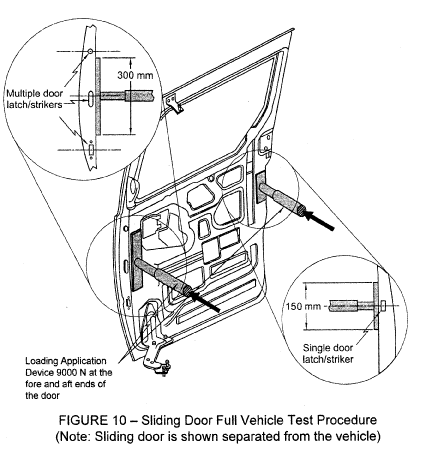
S5.2.2.2 The test is conducted using two force application devices capable of applying the outward transverse forces specified in S5.2.2.4. The test setup is shown in Figure 10. The force application system shall include the following:
(a) Two force application plates,
(b) Two force application devices capable of applying the outward transverse load requirements for a minimum displacement of 300 mm.
(c) Two load cells of sufficient capacity to measure the applied loads specified in S5.2.2.4.
(d) Two linear displacement measurement devices required for measuring force application device displacement during the test.
(e) Equipment to measure for a 100 mm separation as specified in S4.2.2.2(a), while respecting all relevant safety and health requirements.
S5.2.2.3 Test Setup.
(a) Remove all interior trim and decorative components from the sliding door assembly.
(b) Remove seats and any interior components that may interfere with the mounting and operation of the test equipment and all pillar trim and any non-structural components that overlap the door and cause improper placement of the force application plates.
(c) Each force application device and associated support structure is rigidly fixed on a horizontal surface on the vehicle floor, while applying the loads.
(d) Determine the forward and aft edge of the sliding door, or its adjoining vehicle structure, that contains a latch/striker.
(e) Close the sliding door, ensuring that all door retention components are fully engaged.
(f) For any tested door edge that contains one latch/striker, the following set-up procedures are used:
(1)(i) The force application plate is 150 mm in length, 50 mm in width, and at least 15 mm in thickness. The plate edges are rounded to a radius of 6 mm ± 1 mm.
(ii) The plates are fixed perpendicular to the force application devices and move in the transverse direction. For alignment purposes, each plate is attached to the application device in a manner that allows for rotation about the vehicle’s y-axis. In this manner, the face of each plate remains parallel to the vertical plane which passes through the vehicle’s longitudinal centerline.
(2) Place the force application device and force application plate against the door so that the applied force is perpendicular to the vertical longitudinal plane that passes through the vehicle's longitudinal centerline, and vertically centered on the door-mounted portion of the latch/striker.
(3) The force application plate is positioned such that the long edge of the plate is as close to the interior edge of the door as possible, but not such that the forward edge of forward plate and the rear edge of the rear plate are more than 12.5 mm from the respective interior edges.
(g) For any tested door edge that contains more than one latch/striker, the following setup procedures are used:
(1)(i) The force application plate is 300 mm in length, 50 mm in width, and at least 15 mm in thickness. The plate edges are rounded to a radius of 6 mm ±1 mm.
(ii) The plates are fixed perpendicular to the force application devices and move in the transverse direction. For alignment purposes, each plate is attached to the application device in a manner that allows for rotation about the vehicle’s y-axis. In this manner, the face of each plate remains parallel to the vertical plane which passes through the vehicle’s longitudinal centerline.
(2) Place the force application device and force application plate against the door so that the applied force is perpendicular to the vertical longitudinal plane that passes through the vehicle's longitudinal centerline, and vertically centered on a point mid-way between the outermost edges of the latch/striker assemblies.
(3) The force application plate is positioned such that the long edge of the plate is as close to the interior edge of the door as possible, but not such that the forward edge of forward plate and the rear edge of the rear plate are more than 12.5 mm from the respective interior edges.
(h) For any tested door edge that does not contain at least one latch/striker, the following set-up procedures are used:
(1)(i) The force application plate is 300 mm in length, 50 mm in width, and at least 15 mm in thickness. The plate edges are rounded to a radius of 6 mm ± 1 mm.
(ii) The plates are fixed perpendicular to the force application devices and move in the transverse direction. For alignment purposes, each plate is attached to the application device in a manner that allows for rotation about the vehicle’s y-axis. In this manner, the face of each plate remains parallel to the vertical plane which passes through the vehicle’s longitudinal centerline.
(2) Place the force application device and force application plate against the door so that the applied force is perpendicular to the vertical longitudinal plane that passes through the vehicle's longitudinal centerline, and vertically centered on a point mid-way along the length of the door edge ensuring that the loading device avoids contact with the window glazing.
(3) The force application plate is positioned such that the long edge of the plate is as close to the interior edge of the door as possible, but not such that the forward edge of forward plate and the rear edge of the rear plate are more than 12.5 mm from the respective interior edges.
(i) The door is unlocked. No extra fixtures or components may be welded or affixed to the sliding door or any of its components.
(j) Place the load application structure so that the force application plates are in contact with the interior of the sliding door.
(k) Apply a preload of 500 N to each actuator and “zero” the displacement measuring device.
S5.2.2.4 Test Procedure.
(a)Increase the force on each force application device as linearly as practicable until a force of 9,000 N is achieved on each force application device in not less than 90 seconds and not more than 120 seconds, or until either force application device reaches a total displacement of 300 mm.
(b) If one of the force application devices reaches the target force of 9,000 N prior to the other, maintain the 9,000 N force with that force application device until the second force application device reaches the 9,000 N force.
(c) Once both force application devices have achieved 9,000 N each hold the resulting load.
(d) Maintain each force application device load as specified in paragraph (c) and within 30 seconds measure the separation between the exterior edge of the doorframe and the interior of the door along the perimeter of the door.
S5.3 [Reserved]
[36 FR 22902, Dec. 2, 1971, as amended at 37 FR 284, Jan. 8, 1972; 50 FR 12031, Mar. 27, 1985; 60 FR 13646, Mar. 14, 1995; 60 FR 50134, Sept. 28, 1995; 61 FR 39907, July 31, 1996; 72 FR 5399, June 27, 2007; 74 FR 35135, July 20, 2009; 74 FR 37176, July 28, 2009; 75 FR 7382, Feb. 19, 2010; 77 FR 764, Jan. 6, 2012; 87 FR 18588, March 30, 2022]
READ MORESHOW LESS
['CMV Parts and Maintenance']
['Vehicle maintenance']
Load More
J. J. Keller is the trusted source for DOT / Transportation, OSHA / Workplace Safety, Human Resources, Construction Safety and Hazmat / Hazardous Materials regulation compliance products and services. J. J. Keller helps you increase safety awareness, reduce risk, follow best practices, improve safety training, and stay current with changing regulations.
Copyright 2024 J. J. Keller & Associate, Inc. For re-use options please contact copyright@jjkeller.com or call 800-558-5011.
